4K Ultra HD Extender over One Fiber - w/ RS-232 and 2-way IR User Manual
←
→
Page content transcription
If your browser does not render page correctly, please read the page content below

*Preferred

4K Ultra HD Extender
   over One Fiber
  w/ RS-232 and 2-way IR
    EXT-HDRS2IR-4K2K-1FO

       User Manual

         RELEASE A1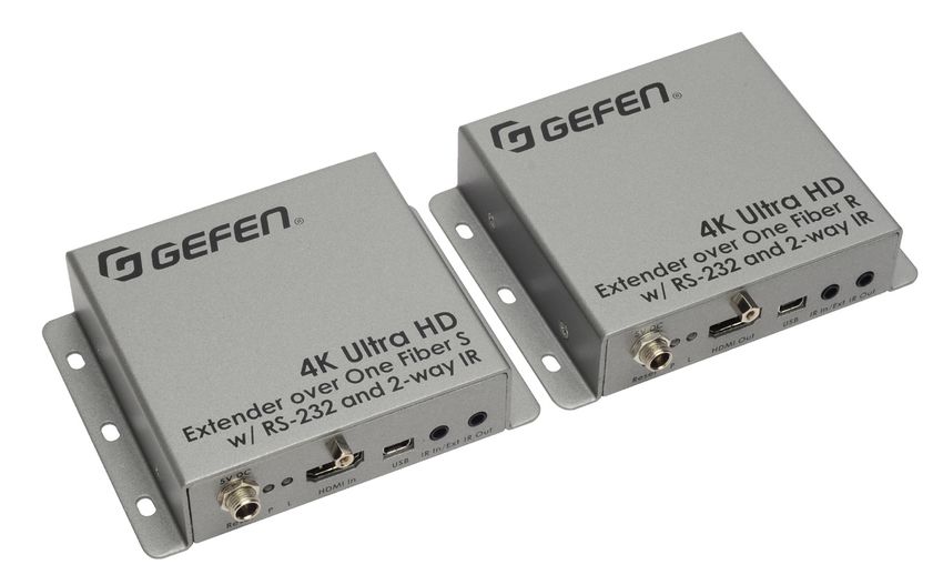
Important Safety Instructions

1.   Read these instructions.

2.   Keep these instructions.

3.   Heed all warnings.

4.   Follow all instructions.

5.   Do not use this product near water.

6.   Clean only with a dry cloth.

7.   Do not block any ventilation openings. Install in accordance with the manufacturer’s
     instructions.

8.   Do not install or place this product near any heat sources such as radiators, heat
     registers, stoves, or other apparatus (including amplifiers) that produce heat.

9.   Do not defeat the safety purpose of the polarized or grounding-type plug. A polarized
     plug has two blades with one wider than the other. A grounding type plug has two
     blades and a third grounding prong. The wide blade or the third prong are provided for
     your safety. If the provided plug does not fit into your outlet, consult an electrician for
     replacement of the obsolete outlet.

10. Protect the power cord from being walked on or pinched particularly at plugs,
    convenience receptacles, and the point where they exit from the apparatus.

11. Only use attachments/accessories specified by the manufacturer.

12. To reduce the risk of electric shock and/or damage to this product, never handle or
    touch this unit or power cord if your hands are wet or damp. Do not expose this
    product to rain or moisture.

13. Unplug this apparatus during lightning storms or when unused for long periods of time.

14. Refer all servicing to qualified service personnel. Servicing is required when the
    apparatus has been damaged in any way, such as power-supply cord or plug is
    damaged, liquid has been spilled or objects have fallen into the apparatus,
    the apparatus has been exposed to rain or moisture, does not operate normally,
    or has been dropped.

15. Batteries that may be included with this product and/or accessories should never be
    exposed to open flame or excessive heat. Always dispose of used batteries
    according to the instructions.

                                               ii
Warranty Information

Gefen warrants the equipment it manufactures to be free from defects in material and
workmanship.

If equipment fails because of such defects and Gefen is notified within two (2) years from
the date of shipment, Gefen will, at its option, repair or replace the equipment, provided
that the equipment has not been subjected to mechanical, electrical, or other abuse or
modifications. Equipment that fails under conditions other than those covered will be
repaired at the current price of parts and labor in effect at the time of repair. Such repairs
are warranted for ninety (90) days from the day of reshipment to the Buyer.

This warranty is in lieu of all other warranties expressed or implied, including without
limitation, any implied warranty or merchantability or fitness for any particular purpose, all of
which are expressly disclaimed.

1.   Proof of sale may be required in order to claim warranty.
2.   Customers outside the US are responsible for shipping charges to and from Gefen.
3.   Copper cables are limited to a 30 day warranty and cables must be in their original
     condition.

The information in this manual has been carefully checked and is believed to be accurate.
However, Gefen assumes no responsibility for any inaccuracies that may be contained
in this manual. In no event will Gefen be liable for direct, indirect, special, incidental, or
consequential damages resulting from any defect or omission in this manual, even if
advised of the possibility of such damages. The technical information contained herein
regarding the features and specifications is subject to change without notice.

For the latest warranty coverage information, refer to the Warranty and Return Policy under
the Support section of the Gefen Web site at www.gefen.com.

                                               iii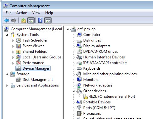
Contacting Gefen Technical Support

Technical Support
8:00 AM to 5:00 PM Monday - Friday, Pacific Time
(818) 772-9100     (800) 545-6900

Fax
(818) 772-9120

Email
support@gefen.com

Web
http://www.gefen.com

Mailing Address
Gefen, LLC
c/o Customer Service
20600 Nordhoff St.
Chatsworth, CA 91311

Product Registration
Register your product online by visiting the Register Product page under the Support
section of the Gefen Web site.

                                            iv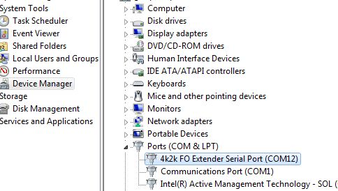
Operating Notes

•        This product operates with SC-terminated single strand multimode fiber optic cable.
         Singlemode fiber is not supported.

               4K Ultra HD Extender over One Fiber w/ RS-232 and 2-way IR is a trademark of Gefen, LLC.

                                           © 2014 Gefen, LLC. All Rights Reserved.
                                  All trademarks are the property of their respective owners.

      Gefen, LLC reserves the right to make changes in the hardware, packaging, and any accompanying documentation
                                                 without prior written notice.

                            Pb
    This product uses UL or CE listed power supplies.
                                                              v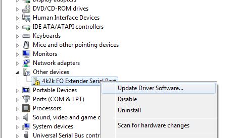
Features and Packing List

Features

•   Extends HDMI, RS-232, and Bi-Directional IR over a single fiber strand
•   Extends Ultra HD 4K x 2K (3840 x 2160 @ 30Hz) up to:
    ►► 3300 feet (1000 meters) over 50/125μm OM3e/OM4 fiber
    ►► 500 feet (150 meters) over 50/125μm (OM3) fiber
    ►► 165 feet (50 meters) over 62.5/125μm (OM1) fiber
•   Extends 1080p Full HD (1920 x 1080 @ 60Hz) up to:
    ►► 6600 feet (2000 meters) over 50/125μm OM3e/OM4 fiber
    ►► 1000 feet (300 meters) over 50/125μm (OM3) fiber
    ►► 330 feet (100 meters) over 62.5/125μm (OM1) fiber
•   Supported HDMI Features
    ►► HDCP-compliant
    ►► 12-bit Deep Color
    ►► LPCM 7.1, Dolby® TrueHD, and DTS-HD Master Audio™
    ►► 3DTV pass-through
    ►► Lip-sync pass-through
•   EDID Management for rapid integration of source and display
•   Full duplex RS-232 up to 115200 baud
•   RS-232 pass-through
•   Automatic calibration based on the type and length of fiber optic cable
•   Immune to electromagnetic interference (EMI)
•   Locking power supplies
•   Firmware upgradable via USB
•   Surface-mountable

                        ®      1080P

                                            vi
Features and Packing List
Packing List
The 4K Ultra HD Extender over One Fiber w/ RS-232 and 2-way IR ships with the items
listed below. If any of these items are not present in the box when you first open it,
immediately contact your dealer or Gefen.
• 1 x 4K Ultra HD Extender over One Fiber w/ RS-232 and 2-way IR (Sender unit)
• 1 x 4K Ultra HD Extender over One Fiber w/ RS-232 and 2-way IR (Receiver unit)
• 1 x 6 ft. HDMI cable (M-M)
• 1 x DB-9 cable (M-F)
• 1 x IR extender
• 1 x IR emitter
• 2 x 5V DC power supplies
• 1 x Quick-Start Guide
viiTable of Contents
1 Getting Started
Introduction............................................................................................................ 2
Sender Unit.................................................................................................... 2
Receiver Unit.................................................................................................. 4
Installation.............................................................................................................. 6
Connection Instructions.................................................................................. 6
Sample Wiring Diagram................................................................................. 6
2 Basic Operation
Bidirectional IR Control........................................................................................ 10
Controlling the Source from the Viewing Location....................................... 10
Controlling the Display from the Source Location........................................ 11
Controlling the Source / Display from Different Locations ��������������������������� 12
LED Indicator Status............................................................................................ 13
DIP Switch Configuration..................................................................................... 15
Baud Rate.................................................................................................... 16
Using RS-232....................................................................................................... 17
3 Appendix
Updating the Firmware......................................................................................... 20
Installing the Device Driver.......................................................................... 20
Updating the Firmware................................................................................. 25
Surface Mounting Instructions.............................................................................. 28
Specifications....................................................................................................... 29
viii4K Ultra HD Extender
over One Fiber
w/ RS-232 and 2-way IR
1 Getting Started
Introduction............................................................................................................ 2
Sender Unit.................................................................................................... 2
Receiver Unit.................................................................................................. 4
Installation.............................................................................................................. 6
Connection Instructions.................................................................................. 6
Sample Wiring Diagram................................................................................. 6Introduction Page Title
Getting Started
Sender Unit
1 2
EXT-HDRS2IR-4K2K-1FOS
EXT-HDRS2IR-4K2K-1FOS
EXT-HDRS2IR-4K2K-1FOS
RS-232 Fiber
RS-232 Fiber
RS-232 Fiber
®
®
®
4K Ultra HD
4KOne
Extender over Ultra HDS
Fiber
Extender 4Kand
over
w/ RS-232 Ultra
One HD
Fiber
2-way S
IR
w/ RS-232
Extender overand
One2-way
FiberIR
S
w/ RS-232 and 2-way IR
3
5V DC 5 7 8 9 10
5V DC
6
5V DC
Reset P L HDMI In USB IR In/Ext IR Out
Reset P L HDMI In USB IR In/Ext IR Out
Reset P L HDMI In USB IR In/Ext IR Out
4
page | 2Introduction
Page Title
Getting Started
ID Name Description
1 RS-232 Connect an RS-232 cable from this port to
an RS-232 device. See Using RS-232 (page
17) for more information.
2 Fiber Connect an SC-terminated multimode fiber
optic cable from this connector to the Fiber
connector on the Receiver unit.
3 5V DC Connect the included 5V DC power supply to
this locking power receptacle.
4 Reset Press this button, using the end of a paper
clip or other pointed object, to power-cycle
the Sender unit. This is the same as
disconnecting and reconnecting the power
supply.
5 P Under normal operating conditions, this
LED indicator will glow bright blue.
See LED Indicator Status (page 13) for
details on LED status messages.
6 L Under normal operating conditions, this
LED indicator will glow bright green.
See LED Indicator Status (page 13) for
details on LED status messages.
7 HDMI In Use the included HDMI cable to connect a
Ultra Hi-Def source to this HDMI port.
8 USB Used for upgrading the firmware.
See Updating the Firmware (page 20)
for more information.
9 IR In/Ext Connect an IR Extender (Gefen part no.
EXT-RMT-EXTIRN) to this port. Alternatively,
connect the 3.5mm mini-stereo connector
of the IR cable from the IR In/Ext port to the
automation system.
10 IR Out Connect the included single infrared IR
emitter from this jack to the IR sensor on the
source device.
page | 3Introduction
Page Title
Getting Started
Receiver Unit
1 2
EXT-HDRS2IR-4K2K-1FOR
EXT-HDRS2IR-4K2K-1FOR
EXT-HDRS2IR-4K2K-1FOR
RS-232 Fiber
RS-232 Fiber
RS-232 Fiber
®
®
®
4K Ultra HD
4KOne
Extender over Ultra HDR
Fiber
Extender 4Kand
over
w/ RS-232 Ultra
One HD
Fiber
2-way R
IR
w/ RS-232
Extender overand
One2-way
FiberIRR
w/ RS-232 and 2-way IR
3
5V DC 5 7 8 9 10
5V DC
6
5V DC
Reset P L HDMI Out USB IR In/Ext IR Out
Reset P L HDMI Out USB IR In/Ext IR Out
Reset P L HDMI Out USB IR In/Ext IR Out
4
page | 4Introduction
Page Title
Getting Started
ID Name Description
1 RS-232 Connect an RS-232 cable from this port to
an RS-232 device. See Using RS-232 (page
17) for more information.
2 Fiber Connect an SC-terminated multimode fiber
optic cable from this connector to the Fiber
connector on the Sender unit.
3 5V DC Connect the included 5V DC power supply to
this locking power receptacle.
4 Reset Press this button, using the end of a paper
clip or other pointed object, to power-cycle
the Receiver unit. This is the same as
disconnecting and reconnecting the power
supply.
5 P Under normal operating conditions, this
LED indicator will glow bright blue.
See LED Indicator Status (page 13) for
details on LED status messages.
6 L Under normal operating conditions, this
LED indicator will glow bright green.
See LED Indicator Status (page 13) for
details on LED status messages.
7 HDMI Out Use an HDMI cable to connect an Ultra
Hi-Def display to this HDMI port.
8 USB Used for upgrading the firmware.
See Updating the Firmware (page 20)
for more information.
9 IR In/Ext Connect the included IR extender to this
port. Alternatively, connect the 3.5mm
mini-stereo connector of the IR cable from
the IR In/Ext port to the automation system.
10 IR Out Connect an IR emitter (Gefen part no. EXT-
IREMIT) from this jack to the IR sensor on
the source device.
page | 5Installation Page Title
Getting Started
Connection Instructions
►► Video
1. Connect the included HDMI cable between the Ultra Hi-Def source and the HDMI In
port on the Sender unit.
2. Connect an Ultra HD display to the HDMI Out port on the Receiver unit using another
HDMI cable.
►► Fiber
3. Connect a single multimode SC-terminated fiber optic cable, up to 6600 feet
(2000 meters), between the Fiber port on the Sender unit and the Fiber port on
the Receiver unit. See the table, below for details on fiber cable types and distance.
►► IR
4. For information on using IR control, see Bidirectional IR Control (page 10) for more
information.
►► Power
5. Use the included locking power supplies to connect the Sender and Receiver unit to
available electrical outlets. Do not overtighten the locking power connectors.
Sample Wiring Diagram
FIBER OPTIC (SC-SC) CABLE
HDMI CABLE
RS-232 CABLE
IR IN
Ultra HD Source
IR Emitter IR OUT
Sender IR Extender
(EXT-RMT-EXTIRN)
Receiver
Ultra HD Display
OR
IR Extender
(EXT-RMT-EXTIRN)
Automation
Control Device
OR
RS-232
Controlled Unit
IR Emitter
EXT-HDRS2IR-4K2K-1FO
page | 64K Ultra HD Extender
over One Fiber
w/ RS-232 and 2-way IR
2 Basic Operation
Bidirectional IR Control........................................................................................ 10
Controlling the Source from the Viewing Location....................................... 10
Controlling the Display from the Source Location........................................ 11
Controlling the Source / Display from Different Locations ��������������������������� 12
LED Indicator Status............................................................................................ 13
DIP Switch Configuration..................................................................................... 15
Baud Rate.................................................................................................... 16
Using RS-232....................................................................................................... 17EXT-HDRS2IR-4K2K-1FOS
Bidirectional IR Control
RS-232 Fiber
Basic Operation
Controlling the Source from the Viewing Location
1. Connect the included IR extender to the IR In/Ext port on the Receiver unit. If using an
automation system, connect the 3.5mm mini-stereo connector from the IR In/Ext port on
the Receiver unit to the automation system.
®
2. ConnectEXT-HDRS2IR-4K2K-1FOR
the included IR emitter from the IR Out port on the Sender unit to the
IR sensor window on the source device.
RS-232 Fiber
4K Ultra HD Ultra HD source
Extender over One Fiber S
w/ RS-232 and 2-way
®
IR
IR emitter
HDMI cable
5V DC
Reset P L HDMI In USB IR In/Ext IR Out
Sender unit 4K Ultra HD
to Fiber port
Extender over One Fiber R
w/ RS-232 and 2-waySCIRfiber optic cable
HDMI cable up to 6600 feet (2000 meters)
to Ultra HD display
to Fiber port
5V DC
Reset P L HDMI Out USB IR In/Ext IR Out
Receiver unit
IR extender or from Automation
System
IR signals
page | 10Bidirectional IR Control
®
Basic Operation
Controlling the Display from the Source Location
EXT-HDRS2IR-4K2K-1FOR
1. Connect the included IR extender to the IR In port on the Sender unit. If using an
automation system, connect
RS-232 the 3.5mm mini-stereo
Fiber connector from the IR In port on the
Sender unit to the automation system.
2.
on the display. 4K Ultra HD
Connect the included IR emitter from the IR Out port on the Receiver unit to the IR sensor
Extender over One Fiber S
IR extender w/ RS-232 and 2-way
or IR
from Automation
System
®
5V DC
Reset P L HDMI In USB IR In/Ext IR Out
Sender unit HDMI cable to Fiber port
4K Ultra HD
Extender over One Fiber R
SC fiber optic cable
w/ RS-232 and 2-way
from Ultra HD source IR6600 feet (2000 meters)
up to
to Fiber port
5V DC
Reset P L HDMI Out USB IR In/Ext IR Out
Receiver unit IR emitter
HDMI cable
Ultra HD display
IR signals
page | 11Bidirectional IR Control
RS-232 Fiber
Basic Operation
Controlling the Source / Display from Different Locations
Information
Additional IR extenders (Gefen®part no. EXT-RMT-EXTIRN) and IR emitters
(Gefen part no. RMT-IREMIT) will be required for this configuration.
EXT-HDRS2IR-4K2K-1FOR
Using bidirectional IR, the 4K Ultra HD Extender over One Fiber w/ RS-232 and 2-way IR
allows the source and/or display
RS-232 to be controlled
Fiber from the viewing location or the source
location. Refer to the diagram, below, for connection details. The video cables have been
removed for clarity.
IR extender
orHD
4K Ultra from Automation
System
Extender over One Fiber S
w/ RS-232 and 2-way IR
®
IR Signals from
Receiver unit
IR emitter
5V DC
Sender unit
Reset P L HDMI In USB IR In/Ext IR Out
4K Ultra
to Fiber port HD
Extender over One Fiber R
w/ RS-232 and 2-way SC
IR fiber optic cable
up to 6600 feet (2000 meters)
to Fiber port
5V DC
Receiver unit
Reset P L HDMI Out USB IR In/Ext IR Out
IR emitter
IR Signals from
Sender unit
IR extender or from Automation
System
IR signals
page | 12Basic Operation
The Power (P) and Link (L) LED indicators on the Sender and Receiver unit provides basic information on the current status of the 4K Ultra HD Extender
over One Fiber w/ RS-232 and 2-way IR.
Sender unit Receiver unit Description
P L P L • Normal operation
P L P L • Display (sink) device is not connected to the Receiver unit OR the source device is not
connected to the Sender unit.
LED Indicator Status
• Link LED on Sender unit slowly flashes bright green.
P L P L • Fiber cable has been disconnected from the Sender or Receiver unit OR the fiber cable
page | 13
may be damaged.
• The Link LED flashes quickly on the Sender unit; the Link LED flashes slower on the
Receiver unit.
P L P L • USB cable has been connected between the computer and the Sender unit.
See Updating the Firmware (page 20) for more information.
• The Link LED on both the Sender and Receiver unit flash at the same rate of speed.
P L P L • USB cable has been connected between the computer and the Receiver unit.
See Updating the Firmware (page 20) for more information.
• The Link LED flashes quickly on the Sender unit; the Link LED flashes slower on the
Receiver unit.
(continued on next page)Basic Operation
Sender unit Receiver unit Description
• The Receiver unit is not powered.
P L P L
• The Link LED flashes quickly on the Sender unit.
P L P L • The Sender unit is not powered.
• The Link LED flashes on the Receiver unit.
The following table outlines the LED status when the firmware is being updated. See Updating the Firmware (page 20) for more information.
page | 14
Sender unit Receiver unit Description
P L P L • The Sender unit is being updated in 2x OR 10x mode.
• The Link LED on the Sender unit is solid green.
• The Power LED on the Receiver unit is solid blue; the Link LED on the Receiver unit will
flash bright red.
• The Receiver unit is being updated in 2x OR 10x mode.
P L P L
• The Link LED on the Receiver unit is solid green.
• The Power LED on the Sender unit is solid blue; the Link LED on the Sender unit will
flash bright red.
LED Indicator StatusDIP SwitchEXT-HDRS2IR-4K2K-1FOS
Configuration RS-232
The bottom of the Sender unit has two banks of DIP switches. The bottom of the Receiver
Basic Operation
unit has a single bank of DIP switches.
RS-232Each bank is comprised
Fiber of four DIP switches.
Each DIP switch provides control over a different function. Remove the piece of colored
tape to reveal the DIP switch banks.
ON SAB
1234
1234
ON SAB
Sender unit
ON SAB
1234
1234
ON SAB
EXT-HDRS2IR-4K2K-1FOR
RS-232 Fiber
5V DC
ON SAB
1234
5V DC
Reset P L HDMI In USB IR In/Ext IR Out
Receiver unit
Reset P L HDMI In US
ON SAB
1234
5V DC page | 15
5V DCDIP Switch Configuration
As of this writing, the only available feature supported by the DIP switches is the baud rate.
Basic Operation
Other DIP switches are reserved for future use.
Baud Rate
The baud rate is controlled by DIP switches on the Sender unit. Use the following DIP
switch settings to configure the port speed of the RS-232 interface. See Using RS-232
(page 17) for more information.
Description Sender unit Receiver unit
115200 Bps
ON SAB ON SAB ON SAB
1 2 3 4 5 6 7 8 1 2 3 4
19200 Bps
(default) ON SAB ON SAB ON SAB
1 2 3 4 5 6 7 8 1 2 3 4
57600 Bps
ON SAB ON SAB ON SAB
1 2 3 4 5 6 7 8 1 2 3 4
9600 Bps
ON SAB ON SAB ON SAB
1 2 3 4 5 6 7 8 1 2 3 4
page | 16Using RS-232
The 4K Ultra HD Extender w/ RS-232 and 2-way IR supports RS-232 pass-through,
Basic Operation
allowing the control of remote RS-232 devices. The Sender and Receiver unit which are
being used to pass-through the RS-232 data must be set to the same baud rate as the
RS-232 host and client. The example, below, shows a sample application. The video
cables have been removed for clarity.
Figure 2.1 - Sample RS-232 connection
RS-232 cable
Sender
Automation
Control Device
Receiver
SC-SC fiber cable
RS-232 cable
RS-232 Controlled
Device
1. Connect the RS-232 automation device to the desired Sender unit.
2. Connect the RS-232-controlled display (or other RS-232 device) to the Receiver unit.
3. Set the required baud rate using the DIP switches on the bottom of the Sender unit.
Consult the User Manual for the client device for the proper RS-232 settings.
See Baud Rate (page 16) for more information on setting the DIP switches.
RS-232 pinout Pin Signal Description
1 DCD Data Carrier Detect
5 4 3 2 1
2 RXD Receive Data
3 TXD Transmit Data
DE-9
4 DTR Data Terminal Ready
5 GND Signal Ground
6 DSR Data Set Ready
7 RTS Request to Send
6 7 8 9
8 CTS Clear to Send
NOTE: Only TX, RX, and GND are used. DA-15
9 RI Ring Indicator
page | 17
DB-254K Ultra HD Extender
over One Fiber
w/ RS-232 and 2-way IR
3 Appendix
Updating the Firmware......................................................................................... 20
Installing the Device Driver.......................................................................... 20
Updating the Firmware................................................................................. 25
Surface Mounting Instructions.............................................................................. 28
Specifications....................................................................................................... 29Updating the Firmware
Appendix
Installing the Device Driver
If you are updating the firmware for the first time, the 4K Ultra HD Extender over One Fiber
w/ RS-232 and 2-way IR device driver must be installed.
1. Connect the included 5V DC power supply to the Sender unit.
2. Connect a USB cable (not included) from the Sender unit to the PC. Both the Sender
and Receiver unit accept a USB Mini-B plug.
3. The P LED indicator will glow solid blue. The L LED indicator will flash green.
4. From the Windows Desktop, click the Start button.
5. Select Computer, then right-click on Manage.
page | 20Updating the Firmware
6. The Computer Management window will open.
Appendix
7. In the left window pane, under System Tools, click Device Manager.
8. In the right window pane, locate Other devices. The device “4k2k FO Extender
Serial Port” will be displayed.
4k2k FO Extender Serial Port
9. Select and right-click the “4k2k FO Extender Serial Port” device.
10. From the context menu, select Update Driver Software...
page | 21Updating the Firmware
11. Select Browse my computer for driver software.
Appendix
12. Click the Browse... button.
13. Select the directory containing the 4K2KFiberOpticExtender.inf file, then click
the OK button.
(continued on next page)
page | 22Updating the Firmware
14. The following Windows Security dialog will be displayed:
Appendix
15. Click Install this driver software anyway to being installing the driver. This process
may take several minutes.
(continued on next page)
page | 23Updating the Firmware
16. Once the driver has been successfully installed, the following dialog will be displayed:
Appendix
The COM port for the driver will also be indicated. COM12 is shown in the examples
below. Your COM port assignment may vary.
17. Click the Close button.
The installed driver will now be displayed under the Computer Management window.
New Virtual COM port
(continued on next page)
page | 24Updating the Firmware
Appendix
Updating the Firmware
Before beginning the update procedure, make sure you have the following:
►► Windows® PC with installed terminal-emulation program
►► Mini USB cable
►► 4K Ultra HD Extender over One Fiber w/ RS-232 and 2-way IR Sender and Receiver
unit(s)
1. Download the latest firmware here: http://www.gefen.com/support/
download.jsp
2. Extract the contents of the .zip file to the desktop on your computer.
3. Make sure the power is connected to both the Sender and Receiver unit.
4. Connect a USB cable (not included) from the Sender unit to the PC. Both the Sender
and Receiver unit accept a USB Mini-B plug.
The order in which the Sender and Receiver unit are updated does not matter. In this
example, we will be starting with the Sender unit.
5. The P LED indicator will glow solid blue. The L LED indicator will flash green.
6. Launch the desired terminal program.
7. Set the serial port to the COM port that was created by the 4k2k FO Extender Serial
Port driver.
8. Press any key on the computer keyboard.
9. The following menu system will be displayed:
------ Sender Appl Menu (Ver 1.15) --------
Remote operation temporary not allowed
Download Omron Data file_________________1
Download Sender 2xx MCU FW______________4
Download Sender 10x MCU FW______________5
View 10x version and Omron Data file_____6
Upgrade Now / Reboot____________________9
Cancel__________________________________0
==========================================
(continued on next page)
page | 25Updating the Firmware
10. Press ‘4’ on the computer keyboard. The following will be displayed:
Appendix
Please send FW file for Sender 2xx MCU
Waiting for the file to be sent ... (press ‘a’ to abort)
CCCCCCCCCC
11. Begin the file transfer using the terminal program. For example, if using
Hyperterminal, click Transfer > Send File...
12. Select the following firmware file: FO2K4K_20xS_app_[version].bin.
Firmware files for the Sender unit will contain the characters 10xS and 20xS.
13. Select the YModem protocol and click the OK button.
14. The firmware update process will begin.
15. After the process has completed, the following will be displayed. Note that the
number, next to “Size”, may vary depending upon the file:
Download Completed Successfully!
Size: 20720
16. Press ‘5’ on the computer keyboard. The following will be displayed:
Please send FW file for Sender 10x MCU
Waiting for the file to be sent ... (press ‘a’ to abort)
CCCCCCCCCC
17. Click Transfer > Send File...
18. Select the following firmware file: FO2K4K_10xS_app_[version].bin.
19. Select the YModem protocol and click the OK button.
20. After the update process has completed, disconnect the USB cable from the
Sender unit.
21. Reboot the Sender unit using any one of the following methods:
a. Press ‘9’ on the computer keyboard.
b. Press the Reset button on the front of the unit.
c. Disconnect and reconnect the power cable from the power receptacle.
22. The Sender unit is now updated.
page | 26Updating the Firmware
23. Connect the USB cable to the Receiver unit.
Appendix
24. Press any key on the computer keyboard. The following will be displayed:
------ Receiver Appl Menu (Ver 1.15) ------
Remote operation temporary not allowed
Download Receiver 2xx MCU FW____________2
Download Receiver 10x MCU FW____________3
View 10x version and set Equalizer______6
Upgrade Now / Reboot____________________9
Cancel__________________________________0
==========================================
25. Repeat the same process for the Receiver unit. Use the following firmware files for
the Receiver unit:
FO2K4K_10xR_app_[version].bin.
FO2K4K_20xR_app_[version].bin.
Firmware files for the Receiver unit will contain the characters 10xR and 20xR.
26. Press ‘2’ on the computer keyboard and upload the
FO2K4K_20xR_app_[version].bin firmware file.
27. Wait for the update process to complete.
28. Press ‘3’ on the computer keyboard and upload the
FO2K4K_10xR_app_[version].bin firmware file.
29. Wait for the update process to complete.
30. After the update process has completed, disconnect the USB cable from the
Receiver unit.
31. Reboot the Receiver unit using any one of the methods that are outlined in step 21.
32. The update process for the Receiver unit is complete.
page | 27Surface Mounting Instructions
The Sender and Receiver units can be mounted on any flat surface, as shown below
Appendix
(screws not included). There should be an inch or two of clearance between the edges of
the unit and any walls or vertical surfaces to allow for enough clearance for connection and
disconnection of the HDMI cables.
For installation on a drywall surface, use a #6 drywall screw. When installing, it is
recommended to use the center hole on a stud.
page | 28Specifications
Appendix
Supported Formats
Video • 4K x 2K (Ultra HD)
• 1920 x 1200 (WUXGA)
• 1080p Full HD
Audio • 7.1 Linear PCM
• Dolby® Digital
• DTS-HD Master Audio™
Connectors, Indicators, and Controls
Video Input (Sender) • 1 x HDMI Type A, 19-pin, female
Video Output (Receiver) • 1 x HDMI Type A, 19-pin, female
Link (Sender / Receiver) • 1 x SC-type, female
RS-232 (Sender) • 1 x DB-9, female
RS-232 (Receiver) • 1 x DB-9, male
IR Out (Sender / Receiver) • 1 x 3.5mm mini-mono, female
IR In / Ext (Sender / Receiver) • 1 x 3.5mm mini-stereo, female
Power (Sender / Receiver) • 1 x Locking-type
Power Indicator (Sender / Receiver) • 1 x LED, blue / red
Link Indicator (Sender / Receiver) • 1 x LED, green / red
DIP switches (Sender) • 2 x banks, 4 each
DIP switches (Receiver) • 1 x bank, 4 each
Operational
Maximum Pixel Clock • 300 MHz
Power Input (ea.) • 5V DC
Power Consumption (ea.) • 2.5W (max.)
IR Carrier Frequency Range • 30 kHz to 60 kHz
Operating Temperature • +32 to +104 °F (0 to +40 °C)
Physical
Dimensions (W x H x D) • 4.3” x 1.0” x 3.4” (110mm x 26mm x 86mm)
(Sender / Receiver)
Unit Weight (ea.) • 0.4 lb (0.2 kg)
page | 29*Preferred
Stretch it. Switch it. Split it. Gefen’s got it. ®
20600 Nordhoff St., Chatsworth CA 91311
1-800-545-6900 818-772-9100 fax: 818-772-9120
www.gefen.com support@gefen.comYou can also read