Nissan DataScan II User Manual
←
→
Page content transcription
If your browser does not render page correctly, please read the page content below
Nissan DataScan II
   User Manual

    http:\\www.nissandatascan.com
             Rev. 1 2013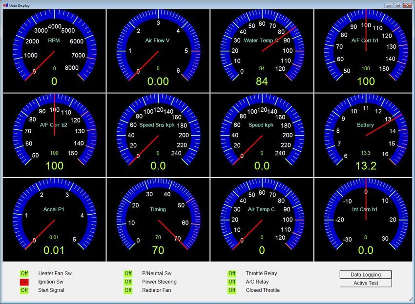
NDSII User Manual

A note to our customers:

This software is provided to assist the enthusiast in performing tuning and data
collection on the user’s car for the purpose of maintenance and performance
improvement. We at Nissan Data Scan strongly suggest you read this manual and
understand the contents before using it on your vehicle.

We make no warranty implied or otherwise regarding the use of this software or
any hardware supplied by Nissan Data Scan.

Where the limitation of liability for incidental or consequential damages in not
allowed, the author’s total liability to you for all damages will not exceed $1.00
AUD.

                                          2
NDSII User Manual

Table of Contents
1.     First time use ........................................................................................................................... 5
     1.1     USB driver installation ..................................................................................................... 5
     1.2     Communication settings ................................................................................................... 5
     1.3     Identifying Com Port number .......................................................................................... 7
     1.4     Software Activation.......................................................................................................... 8
2.     Main Window ....................................................................................................................... 10
3.     Settings .................................................................................................................................. 12
     3.1     Communication .............................................................................................................. 12
       3.1.1        Find BlaztII Adaptor ............................................................................................... 14
       3.1.2        Find ECU ................................................................................................................ 14
     3.2     Preferences ..................................................................................................................... 15
4.     ECM functions ...................................................................................................................... 17
     4.1     Data Display ................................................................................................................... 17
     4.2     Data Logging .................................................................................................................. 19
     4.3     Self Diagnostics.............................................................................................................. 20
     4.4     Idle Adjustment .............................................................................................................. 21
     4.5     Base Timing Adjustment ................................................................................................ 21
     4.6     Active Test ..................................................................................................................... 22
     4.7     Cylinder Power Test ....................................................................................................... 23
     4.8     Speed Test ...................................................................................................................... 24
     4.9     Log Analyser .................................................................................................................. 25
     4.10       Data Replay ................................................................................................................ 27
     4.11       Address Watch ............................................................................................................ 29
     4.12       Work Support ............................................................................................................. 29
     4.13       Parameter Settings ...................................................................................................... 31
5.     BCM functions ...................................................................................................................... 33
     5.1     Data Display ................................................................................................................... 34
     5.2     Self Diagnostics.............................................................................................................. 35
     5.3     Active Test ..................................................................................................................... 36
6.     TCM functions ...................................................................................................................... 37

                                                                         3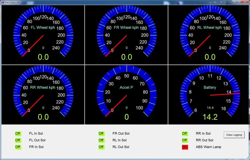
NDSII User Manual

     6.1      Data Display ................................................................................................................... 38
     6.2      Data Logging .................................................................................................................. 40
     6.3      Self Diagnostics.............................................................................................................. 41
     6.4      Log Analyser .................................................................................................................. 42
     6.5      Data Replay .................................................................................................................... 44
     6.6      Parameter Settings .......................................................................................................... 46
7.     ABS functions ....................................................................................................................... 47
     7.1      Data Display ................................................................................................................... 48
     7.2      Data Logging .................................................................................................................. 50
     7.3      Self Diagnostics.............................................................................................................. 51
     7.4      Log Analyser .................................................................................................................. 52
     7.5      Data Replay .................................................................................................................... 54
     7.6      Parameter Settings .......................................................................................................... 56
8.     SRS functions........................................................................................................................ 57
     8.1      Self Diagnostics.............................................................................................................. 58
9.     Diesel ECM (ECMD) functions............................................................................................ 59
     9.1      Data Display ................................................................................................................... 59
     9.2      Data Logging .................................................................................................................. 61
     9.3      Self Diagnostics.............................................................................................................. 62
     9.4      Log Analyser .................................................................................................................. 63
     9.5      Data Replay .................................................................................................................... 65
     9.6      Parameter Settings .......................................................................................................... 67
10.        OBDII functions................................................................................................................. 68
     10.1        Data Display ............................................................................................................... 69
     10.2        Data logging ............................................................................................................... 71
     10.3        Self Diagnostics .......................................................................................................... 71
     10.4        Fuel System Status...................................................................................................... 72
     10.5        Monitor Status ............................................................................................................ 73
     10.6        Log Analyser .............................................................................................................. 74
     10.7        Parameter Settings ...................................................................................................... 76
11.        WBO2 ................................................................................................................................ 78

                                                                        4
NDSII User Manual

   1. First time use

Before you can use the NDSII application you will need to specify the Com Port number for the
OBDII adaptor. The OBDII adaptor uses a USB connection that requires an FTDI driver. The
driver will assign a Com Port number for the adaptor. This Com Port number will then need to
be entered in the Communication settings of the NDSII software.

   1.1     USB driver installation

Connect the OBDII adaptor to a spare USB port on your PC.

Depending on the operating system, Windows might connect to the Windows Update website
and install any suitable driver it finds for the device.

If the automatic installation takes place there is no need to continue with the procedure outlined
below. If no suitable driver is automatically found, select an option to manually specify the
driver location and point to the location where you saved the driver.

The USB drivers are available from our website www.nissandatascan.com. The driver can also
be downloaded from FTDI website http://www.ftdichip.com.

During the installation the FTDI driver will assign a COM Port number for the adaptor. Take
note of the Com Port number as it will be required for the NDSII software configuration.

More detailed instructions for specific operating system can be found on FTDI website:
http://www.ftdichip.com/Support/Documents/InstallGuides.htm.

   1.2     Communication settings

The NDSII software needs to know how to communicate with the OBDII adaptor. This is
achieved by configuring the Com Port number assigned to the adaptor. The Com Port setting is
located on the Communication window accessible from the pull down menu on the main
window, Settings -> Communication.

                                                 5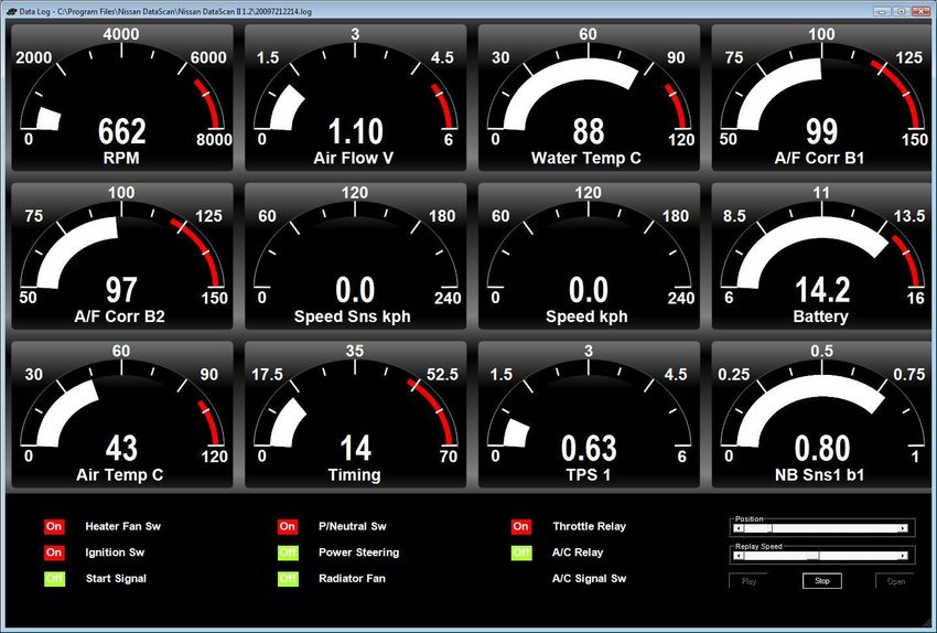
NDSII User Manual

Enter the Com Port number assigned to your adaptor in the “COM Port” setting.

Select the type of adaptor you are using.

Generic adaptor – for generic “dumb” OBDII adaptor i.e. VAG COM 409 adaptor

BlaztII adaptor – for BlaztII design adaptor.

                                                6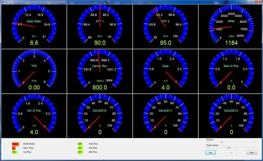
NDSII User Manual

Click on the Save button to save the new settings.

If you do not know the Com Port number assigned to your adaptor follow the instructions below
to identify the Com Port number.

   1.3     Identifying Com Port number

The Com Port number is assigned to your OBDII adaptor by the FTDI driver at the time of
installation. You can also identify it through Windows Device Manager.

Connect the OBDII adaptor to a spare USB port on your PC.

Open your PC’s Device Manager Window from the Control Panel.

If the driver is correctly installed, the OBDII adaptor will be located under “Ports (COM &
LPT)”. You can confirm you have identified the correct device by unplugging the adaptor from
the USB port. The device should disappear from the Device Manager list.

                                                7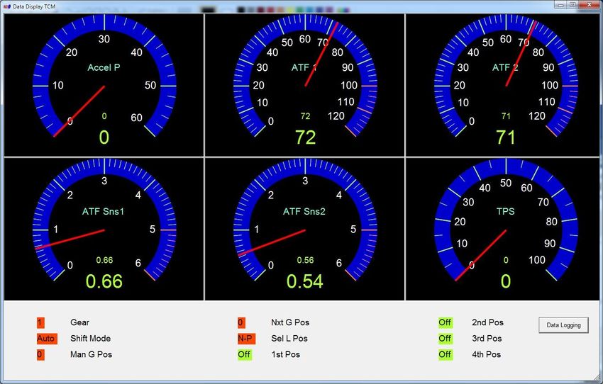
NDSII User Manual

You can also use the Find BlaztII Adaptor function located on the Communication Window to
test all available Com Ports for the presence of a BlaztII adaptor. This function will not identify
generic adaptors.

   1.4     Software Activation

The first time you run the NDSII software you will be prompted to activate the software. Go to
Help->Activation to open the Activation window.

Enter your name and registration email address. Click on the Generate Code button to generate
your Registration Code.

Login to the Nissan DataScan II member’s area using credentials provided when purchasing the
software.

                                                 8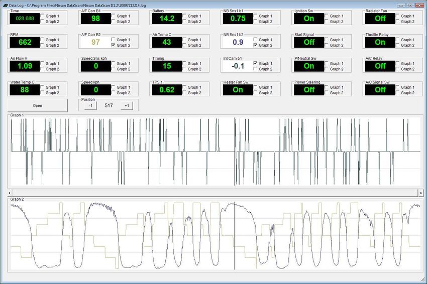
NDSII User Manual

Click on “Register Software” button. Copy and Paste your Registration Code from NDSII
software and click the “Generate Activation Key” button.

Copy and Paste the Activation Key to NDSII software and click the “Unlock” button.

                                              9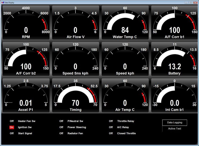
NDSII User Manual

You will receive a pop up message confirming activation of your NDSII software.

The NDSII software is now ready to use.

   2. Main Window

The main window provides access to all functions of Nissan DataScan II software. Some
functions are available “off line” when not connected to an ECU. Other functions are only
available when a connection with an ECU has been established.

The top menu gives access to specific ECU functions and program settings.

The tabs are used to switching between ECUs, wideband sensor or type of connection:

ECM – Consult II protocol, Engine Control Module

BCM – Consult II protocol, Body Control Module

                                              10
NDSII User Manual
TCM – Consult II protocol, Transmission Control Module
ABS – Consult II protocol, ABS Module
SRS – Consult II protocol, Airbag Module
ECMD – Consult II protocol, Diesel Engine Control Module
OBDII – OBDII protocol, Engine Control Module
WBO2 – Innovate Motorsports wide band oxygen sensor
Due to limitations of Consult II protocol only one ECU can be connected at the time. It’s not
possible to establish concurrent connections to multiple ECUs.
After connection has been established, the ECU part number will be displayed. All functions that
require communication with the ECU and are supported by the ECU will be automatically
enabled.
11NDSII User Manual
The progress bar at the bottom indicates communication between the ECU and PC. If the bar is
not moving there is no data being received from the ECU. The status bar also displays the BlaztII
adaptor firmware version and the user preferences settings.
3. Settings
3.1 Communication
The communication settings are available through the main pull down menu, Settings ->
Communication. These settings configure parameters required by the NDSII software to access
your ECUs. The default settings will work for most users.
12NDSII User Manual
COM Port – Com Port number assigned to the OBDII adaptor. See topic “Identifying Com Port
number” if you are not sure what Port number to use.
Generic adaptor – Select when using a generic “dumb” OBDII adaptor i.e. VAG COM 409
adaptor (http://www.tomtop.com/vag-com-obdii-409-1-usb-car-diagnostic-cable-interface.html)
BlaztII adaptor – Select when using a BlaztII design adaptor.
Please note: The ELM327 type adaptors are not supported.
We recommend using a BlaztII design adaptor. They are more reliable in establishing connection
with ECUs. For a low cost setup and occasional use a generic “dumb” OBDII adaptor is also
supported.
If you are having difficulty initiating connection using a generic adaptor try adjusting the Ini
Timer Offset value. This value modifies the timing used in the initiation sequence.
Some generic adaptors require DTR pin on the serial port to be activated for the adaptor to send
the data to the k-line. Enable the DTR setting for this type of adaptors.
Save debug data – This option when selected saves a debug file that can be analysed by NDSII
developers. The file is usually saved in the same directory as the NDSII application but might
vary depending on the operating system. Do not use this option unless specifically instructed by
the Nissan Data Scan staff.
ECU ID in Hex – Target ECU Id. The IDs vary between regions. Tester ID is what the software
uses to identify itself to ECUs. The default settings should work on most cars.
13NDSII User Manual
3.1.1 Find BlaztII Adaptor
The Find BlaztII Adaptor button tests all available Com Ports for the presence of BlaztII
adaptor.
This function can be used to easily identify the Com Port number assigned to the BlaztII adaptor
given the USB driver has previously been installed. After the test, the Com Port number with the
adaptor present needs to be manually entered in the COM Port field.
3.1.2 Find ECU
The Find ECU button tests for active ECUs. It is used to identify ECUs present on the car and
responding to the initiation sequence. You may need to use this function if the default settings
fail to establish communication with the ECU.
14NDSII User Manual
Please note: ECUs other than supported can respond to the query during the Active ECU Test. It
is important to use the correct ECU ID for each type of connection. I.e. use only BCM IDs for
BCM connection and ECM IDs for ECM connection. Each type of ECU supports only a specific
set of features and a specific type of connection needs to be used.
3.2 Preferences
The preferences settings are available through the main pull down menu, Settings -> Preferences.
15NDSII User Manual
The preferences window lets users specify the units used throughout the software.
Speed Unit – Kph or Mph
Temperature Unit – Celsius or Fahrenheit
The Turn off BlaztII adaptor LED option disables the flashing LED on BlaztII cable.
The Gauge Design option specifies the type of gauge design is used throughout the software.
Classic
16NDSII User Manual
Or
Modern
The “Log Analyser Design” option specifies the type of Log Analyser design to be used.
Depending on user preference Classic or Modern design can be used. The modern design offers a
more flexibility.
4. ECM functions
The ECM functions are divided into 2 groups. Basic Functions are useful for general monitoring
of engine parameters and Advanced Functions for use in testing and tuning. They can be
selected from the pull down menu at the top of the Main Screen, by clicking on the large Main
screen buttons or by pressing the corresponding Function Key on the keyboard.
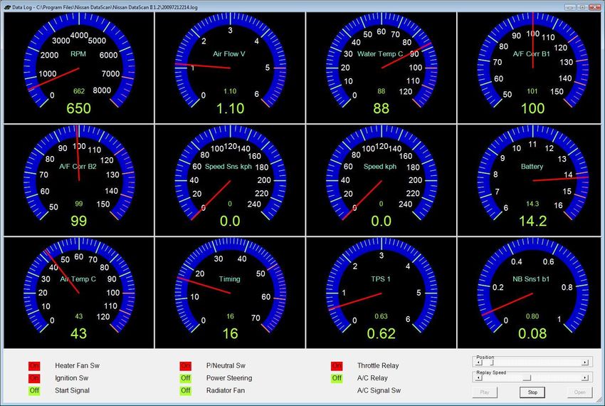
4.1 Data Display
The Data Display function uses 12 gauges and 9 registers to display real time information about
the engine as measured or calculated by the engine ECM. Depending on preferences setting this
window can use either Classic or Modern design gauges.
17NDSII User Manual
Classic
Modern
18NDSII User Manual
Parameters are assigned to gauges in the Data Display Settings window (ECM->Data Display
Settings).
4.2 Data Logging
This function allows the user to select what ECM parameters and registers are logged. It also
provides options for the log file name and location. When the Start button is clicked, the chosen
parameters are logged to a comma delimited text file. The log file can then be reviewed using
Log Analyser function or Data Replay function. The file can also be opened in common
spreadsheet software such as Excel.
The Data Logging function can also be accessed from the Data Display window. A higher update
rate is achieved if the function is started from the Main window.
19NDSII User Manual
4.3 Self Diagnostics
The Self Diagnostics function reports any diagnostic codes present on the ECM. It can also be
used to clear the existing codes if the fault has been fixed.
20NDSII User Manual
4.4 Idle Adjustment
The Idle Adjustment function allows users to adjust the base idle RPM. The setting is saved in an
ECM memory and it does not reset with engine restart. An engine needs to reach a minimum
operating temperature (80 deg C) before this function can be initiated.
This function is mostly used to increase the base idle RPM on modified engines. To lower an
unusually high base idle RPM use an Idle Air Volume Learn function.
4.5 Base Timing Adjustment
The Base Timing Adjustment function allows users to adjust the base ignition timing. The setting
is saved in an ECM memory and it does not reset with engine restart. An engine needs to reach a
minimum operating temperature (80 deg C) before this function can be initiated.
21NDSII User Manual
4.6 Active Test
The Active Test function allows the user to interact directly with the ECM. With this tool,
control parameters can be overridden to evaluate engine system response to individual variables.
For example, setting the Engine Temperature to a particular value makes the ECM respond as if
the temperature was really at that reading. This could be used to diagnose temperature sensor
failures.
Only functions supported by the ECM are activated. The greyed out functions are not supported
by the ECM.
22NDSII User Manual
Fuel Pump – Turns the fuel pump On or Off.
A/F Base % - Base fuel injection as programmed in the fuel map. By temporary increasing this
value you are adding more fuel across the whole fuel map.
Engine Temperature – Overwrites the current engine temperature with the set value. Do not use
this function for long period of time as it may lead to engine overheat.
Fuel Temperature - Overwrites the current fuel temperature with the set value.
Purge Volume Control Valve – Opens the Purge Valve to the set value.
C-VTC – Adjusts the Cam timing to the set value.
EGR Valve – Opens the EGR valve to the set value.
Ignition Timing – Modifies the ignition timing by the set value.
The tests are activated until they are stopped or the engine is turned off. The changes can not be
saved permanently.
This function can also be accessed from the Data Display window.
4.7 Cylinder Power Test
23NDSII User Manual
The Cylinder Power Test function allows the use to turn off individual cylinders. This function
can be used to identify cylinders that are under performing. If all of the cylinders are producing
the same amount of power the engine RPMs will drop exactly the same amount with each
cylinder turned off. The results of the test should be used as a guide for further investigation and
do not represent a definite proof of defective engine.
4.8 Speed Test
This feature provides an accurate method to measure vehicle performance. Select the test to be
performed and click the Activate button. The program monitors the ECM reported vehicle
speed. When the starting speed has been reached (or exceeded in case of 0) it will begin timing.
When the chosen upper limit is reached it will display the elapsed time for that test.
The Cancel button terminates the previously activated speed test.
24NDSII User Manual
4.9 Log Analyser
The Log Analyser provides the ability for the user to graph data logged with the Data Logging
function. The graphical output is useful for evaluating the data in a more chronological fashion.
Graphed logs can be evaluated for trends and compared for cause and effect determination.
There are 2 designs available. The setting in Settings->Preferences determines which one is used.
Classic design
25NDSII User Manual
The data to be graphed is displayed at the top. By checking the appropriate box the data can be
graphed in either the top or bottom graph. Using this capability the logged parameters can be
displayed in the most meaningful fashion. Using the Position buttons, values for discrete time
points may be compared.
Modern design
26NDSII User Manual
The data to be graphed is displayed on the left. By checking the appropriate box the data can be
graphed. The colour of the graph matches the relevant data. Using the Position buttons, values
for discrete time points may be compared.
Select the Show Y Scale option prior to selecting the parameter to display the vertical scale.
The highlighted area in the bottom window represents the currently graphed data in the main
window.
4.10 Data Replay
Use the Data Replay function to “playback” a data log file collected using the Data Logging
function. The playback can be run at real time or stepped through using the Position slider.
There are 2 gauge designs available. The setting in Settings->Preferences determines which one
is used. Both perform exactly the same function.
Classic gauge design
27NDSII User Manual
Modern gauge design
28NDSII User Manual
4.11 Address Watch
Address Watch is an advance function. It is used to monitor specific memory address locations.
This is often used if a tuner needs to monitor a specific function not available through the
Consult II protocol.
Three memory addresses can be monitored at the same time. Enter the Address in the fields at
the top of the window. Click the Start button to start monitoring. The Current, Maximum and
Minimum values are displayed below the address.
4.12 Work Support
Work Support functions allow users to perform some of the advance service procedures. Those
procedures may need to be performed after replacement parts are installed.
29NDSII User Manual
Clear Self Learn – clears the Air/Fuel Base Self Learn map. While running in a closed loop
mode the ECM continuously monitors the Oxygen sensors and corrects the fuel mixture. Those
corrections are saved in ECM’s memory. The ECM uses the saved corrections to quickly achieve
the optimum A/F ratio. This function erases those corrections from the memory and forces the
ECM to relearn them.
Idle Air Volume Learn – an operation to learn the idle air volume that keeps each engine within
the specific range. It must be performed every time the electronic throttle control actuator or
ECM is replaced. It should also be completed when the idle speed or ignition timing is out of
specification.
PREPARATION
Before performing Idle Air Volume Learning, make sure that all of the following conditions are
satisfied. Learning will be cancelled if any of the following conditions are missed for even a
moment.
Battery voltage: More than 12.9V (At idle)
Engine coolant temperature: 70 - 100°C (158 - 212°F)
PNP switch: ON
Electric load switch: OFF (Air conditioner, headlamp, rear window defogger)
Steering wheel: Neutral (Straight-ahead position)
Vehicle speed: Stopped
Transmission: Warmed-up
30NDSII User Manual
If the procedure counts to 5000 and eventually fails it means one or more basic engine control
parameters are out of specification. Check the following and consult your service manual to
rectify the problems:
Check that throttle valve is fully closed.
Check PCV valve operation.
Check that downstream of throttle valve is free from air leakage.
Program Immobiliser Key – registers the Nissan transponder keys with the ECM immobiliser.
Enter the 4 digit immobiliser PIN and click on the Start button. The PIN is stamped on the little
metal tag attached to one of the keys. If the tag is not available the PIN can be obtained from a
Nissan/Infiniti dealer.
This procedure will first erase all registered keys. You will then be able to reregister keys one by
one including any new keys. Keys not registered at this time will no longer be usable.
4.13 Parameter Settings
The Parameter Settings function can be accessed through the main pull down menu, ECM ->
Parameter Settings. It is used for adjusting the value range for each individual parameter. It also
defines the look of the Classic Gauge. It increases or decreases the resolution of the gauge.
31NDSII User Manual
Select the Parameter from the drop down menu at the top. Enter the Minimum, Warning and
Maximum values for the gauge. Enter how many digits after Decimal Point should be
displayed.
The Visual Alert setting causes the gauge to change colour when the warning value is reached.
The Ticker and Sub Ticker settings apply to the classic gauge only. It specifies how many
tickers the gauge should have.
32NDSII User Manual
5. BCM functions
The NDSII software supports BCM diagnostics over the DDL2 communication line.
A lot of Nissan vehicles use DDL2 communication line for engine ECU (ECM) diagnostics but
still use DDL1 communication line for BCM diagnostics. Those vehicles are not supported.
The BCM functions are used for diagnostics and general monitoring of Body Control Module.
They can be selected from the pull down menu at the top of the Main Screen or by clicking on
the large Main screen buttons.
Not all BCM ECUs report their Part Number. The communication can still be established but the
Part Number will not be displayed.
The progress bar at the bottom indicates data transfer between BCM and PC. If the bar is not
moving there is no data being received from the BCM.
33NDSII User Manual
5.1 Data Display
The Data Display window uses 12 registers to display real time information about the BCM
operation.
34NDSII User Manual
Parameters are assigned in the Data Display Settings window (BCM->Data Display Settings).
5.2 Self Diagnostics
The Self Diagnostics function reports any diagnostic codes present on the BCM. It can also be
used to clear the existing codes if the fault has been fixed.
35NDSII User Manual
5.3 Active Test
The Active Test function allows the user to interact directly with the BCM. With this function,
actuators/switches can be manually overwritten to test the BCM functionality.
Only functions supported by the BCM are activated. The greyed out functions are not supported
by the BCM.
The tests are activated until they are stopped or the engine is turned off. The changes can not be
saved permanently.
36NDSII User Manual
6. TCM functions
The NDSII software supports TCM diagnostics over the DDL2 communication line.
A lot of Nissan vehicles use DDL2 communication line for engine ECU (ECM) diagnostics but
still use DDL1 communication line for TCM diagnostics. Those vehicles are not supported.
The TCM functions are used for diagnostics and general monitoring of the Transmission Control
Module. They can be selected from the pull down menu at the top of the Main Screen or by
clicking on the large Main screen buttons.
The progress bar at the bottom indicates data transfer between TCM and PC. If the bar is not
moving there is no data being received from the TCM.
37NDSII User Manual
6.1 Data Display
The Data Display function uses 6 gauges and 9 registers to display real time information about
the transmission as measured or calculated by the TCM. Depending on preferences setting this
window can use either Classic or Modern design gauges.
Classic
38NDSII User Manual
Modern
39NDSII User Manual
Parameters are assigned to gauges in the Data Display Settings window (TCM->Data Display
Settings).
6.2 Data Logging
This function allows the user to select what TCM parameters and registers are logged. It also
provides options for the log file name and location. When the Start button is clicked, the chosen
parameters are logged to a comma delimited text file. The log file can then be reviewed using
Log Analyser function or Data Replay function. The file can also be opened in common
spreadsheet software such as Excel.
The Data Logging function can also be accessed from the Data Display window. A higher update
rate is achieved if the function is started from the Main window.
40NDSII User Manual
6.3 Self Diagnostics
The Self Diagnostics function reports any diagnostic codes present on the TCM. It can also be
used to clear the existing codes if the fault has been fixed.
41NDSII User Manual
6.4 Log Analyser
The Log Analyser provides the ability for the user to graph data logged with the Data Logging
function. The graphical output is useful for evaluating the data in a more chronological fashion.
Graphed logs can be evaluated for trends and compared for cause and effect determination.
There are 2 designs available. The setting in Settings->Preferences determines which one is used.
Classic design
42NDSII User Manual
The data to be graphed is displayed at the top. By checking the appropriate box the data can be
graphed in either the top or bottom graph. Using this capability the logged parameters can be
displayed in the most meaningful fashion. Using the Position buttons, values for discrete time
points may be compared.
Modern design
43NDSII User Manual
The data to be graphed is displayed on the left. By checking the appropriate box the data can be
graphed. The colour of the graph matches the relevant data. Using the Position buttons, values
for discrete time points may be compared.
Select the Show Y Scale option prior to selecting the parameter to display the vertical scale.
The highlighted area in the bottom window represents the currently graphed data in the main
window.
6.5 Data Replay
Use the Data Replay function to “playback” a data log file collected using the Data Logging
function. The playback can be run at real time or stepped through using the Position slider.
There are 2 gauge designs available. The setting in Settings->Preferences determines which one
is used. Both perform exactly the same function.
Classic gauge design
44NDSII User Manual
Modern gauge design
45NDSII User Manual
6.6 Parameter Settings
The Parameter Settings function can be accessed through the main pull down menu, TCM ->
Parameter Settings. It is used for adjusting the value range for each individual parameter. It also
defines the look of the Classic Gauge. It increases or decreases the resolution of the gauge.
Select the Parameter from the drop down menu at the top. Enter the Minimum, Warning and
Maximum values for the gauge. Enter how many digits after Decimal Point should be
displayed.
The Visual Alert setting causes the gauge to change colour when the warning value is reached.
The Ticker and Sub Ticker settings apply to the classic gauge only. It specifies how many
tickers the gauge should have.
46NDSII User Manual
7. ABS functions
The NDSII software supports ABS diagnostics over the DDL2 communication line.
A lot of Nissan vehicles use DDL2 communication line for engine ECU (ECM) diagnostics but
still use DDL1 communication line for ABS diagnostics. Those vehicles are not supported.
The ABS functions are used for diagnostics and general monitoring of the ABS Control Module.
They can be selected from the pull down menu at the top of the Main Screen or by clicking on
the large Main screen buttons.
The progress bar at the bottom indicates data transfer between ABS ECU and PC. If the bar is
not moving there is no data being received from the ABS ECU.
47NDSII User Manual
7.1 Data Display
The Data Display function uses 6 gauges and 9 registers to display real time information about
the ABS system as measured or calculated by the ABS ECU. Depending on preferences setting
this window can use either Classic or Modern design gauges.
Classic
48NDSII User Manual
Modern
49NDSII User Manual
Parameters are assigned to gauges in the Data Display Settings window (ABS->Data Display
Settings).
7.2 Data Logging
This function allows the user to select what ABS parameters and registers are logged. It also
provides options for the log file name and location. When the Start button is clicked, the chosen
parameters are logged to a comma delimited text file. The log file can then be reviewed using
Log Analyser function or Data Replay function. The file can also be opened in common
spreadsheet software such as Excel.
The Data Logging function can also be accessed from the Data Display window. A higher update
rate is achieved if the function is started from the Main window.
50NDSII User Manual
7.3 Self Diagnostics
The Self Diagnostics function reports any diagnostic codes present on the ABS ECU. It can also
be used to clear the existing codes if the fault has been fixed.
51NDSII User Manual
7.4 Log Analyser
The Log Analyser provides the ability for the user to graph data logged with the Data Logging
function. The graphical output is useful for evaluating the data in a more chronological fashion.
Graphed logs can be evaluated for trends and compared for cause and effect determination.
There are 2 designs available. The setting in Settings->Preferences determines which one is used.
Classic design
52NDSII User Manual
The data to be graphed is displayed at the top. By checking the appropriate box the data can be
graphed in either the top or bottom graph. Using this capability the logged parameters can be
displayed in the most meaningful fashion. Using the Position buttons, values for discrete time
points may be compared.
Modern design
53NDSII User Manual
The data to be graphed is displayed on the left. By checking the appropriate box the data can be
graphed. The colour of the graph matches the relevant data. Using the Position buttons, values
for discrete time points may be compared.
Select the Show Y Scale option prior to selecting the parameter to display the vertical scale.
The highlighted area in the bottom window represents the currently graphed data in the main
window.
7.5 Data Replay
Use the Data Replay function to “playback” a data log file collected using the Data Logging
function. The playback can be run at real time or stepped through using the Position slider.
There are 2 gauge designs available. The setting in Settings->Preferences determines which one
is used. Both perform exactly the same function.
Classic gauge design
54NDSII User Manual
Modern gauge design
55NDSII User Manual
7.6 Parameter Settings
The Parameter Settings function can be accessed through the main pull down menu, ABS ->
Parameter Settings. It is used for adjusting the value range for each individual parameter. It also
defines the look of the Classic Gauge. It increases or decreases the resolution of the gauge.
Select the Parameter from the drop down menu at the top. Enter the Minimum, Warning and
Maximum values for the gauge. Enter how many digits after Decimal Point should be
displayed.
The Visual Alert setting causes the gauge to change colour when the warning value is reached.
The Ticker and Sub Ticker settings apply to the classic gauge only. It specifies how many
tickers the gauge should have.
56NDSII User Manual
8. SRS functions
The NDSII software supports SRS diagnostics over the DDL2 communication line.
A lot of Nissan vehicles use DDL2 communication line for engine ECU (ECM) diagnostics but
still use DDL1 communication line for SRS diagnostics. Those vehicles are not supported.
The Self Diagnostics function can be selected from the pull down menu at the top of the Main
Screen or by clicking on the large Main screen button.
The progress bar at the bottom indicates data transfer between SRS ECU and PC. If the bar is not
moving there is no data being received from the SRS ECU.
57NDSII User Manual
8.1 Self Diagnostics
The Self Diagnostics function reports any diagnostic codes present on the SRS ECU. It can also
be used to clear the existing codes if the fault has been fixed.
58NDSII User Manual
The recorded faults are historical and can not be cleared. Those faults have occurred in the past
and have been fixed since. They could be as simple as a failure to reconnect a module or as
serious as air bag deployment due to accident.
9. Diesel ECM (ECMD) functions
The NDSII software supports diesel ECM diagnostics over the DDL2 communication line.
The ECMD functions are used for diagnostics and general monitoring of the diesel ECM. They
can be selected from the pull down menu at the top of the Main Screen or by clicking on the
large Main screen buttons.
The progress bar at the bottom indicates data transfer between ECMD and PC. If the bar is not
moving there is no data being received from the ECMD.
9.1 Data Display
The Data Display function uses 6 gauges and 9 registers to display real time information about
the engine as measured or calculated by the ECM. Depending on preferences setting this window
can use either Classic or Modern design gauges.
59NDSII User Manual
Classic gauge design
Modern gauge design
60NDSII User Manual
Parameters are assigned to gauges in the Data Display Settings window (ECMD->Data Display
Settings).
9.2 Data Logging
This function allows the user to select what ECMD parameters and registers are logged. It also
provides options for the log file name and location. When the Start button is clicked, the chosen
parameters are logged to a comma delimited text file. The log file can then be reviewed using
Log Analyser function or Data Replay function. The file can also be opened in common
spreadsheet software such as Excel.
The Data Logging function can also be accessed from the Data Display window. A higher update
rate is achieved if the function is started from the Main window.
61NDSII User Manual
9.3 Self Diagnostics
The Self Diagnostics function reports any diagnostic codes present on the ECMD. It can also be
used to clear the existing codes if the fault has been fixed.
62NDSII User Manual
9.4 Log Analyser
The Log Analyser provides the ability for the user to graph data logged with the Data Logging
function. The graphical output is useful for evaluating the data in a more chronological fashion.
Graphed logs can be evaluated for trends and compared for cause and effect determination.
There are 2 designs available. The setting in Settings->Preferences determines which one is used.
Classic design
63NDSII User Manual
The data to be graphed is displayed at the top. By checking the appropriate box the data can be
graphed in either the top or bottom graph. Using this capability the logged parameters can be
displayed in the most meaningful fashion. Using the Position buttons, values for discrete time
points may be compared.
Modern design
64NDSII User Manual
The data to be graphed is displayed on the left. By checking the appropriate box the data can be
graphed. The colour of the graph matches the relevant data. Using the Position buttons, values
for discrete time points may be compared.
Select the Show Y Scale option prior to selecting the parameter to display the vertical scale.
The highlighted area in the bottom window represents the currently graphed data in the main
window.
9.5 Data Replay
Use the Data Replay function to “playback” a data log file collected using the Data Logging
function. The playback can be run at real time or stepped through using the Position slider.
There are 2 gauge designs available. The setting in Settings->Preferences determines which one
is used. Both perform exactly the same function.
Classic gauge design
65NDSII User Manual
Modern gauge design
66NDSII User Manual
9.6 Parameter Settings
The Parameter Settings function can be accessed through the main pull down menu, ECMD ->
Parameter Settings. It is used for adjusting the value range for each individual parameter. It also
defines the look of the Classic Gauge. It increases or decreases the resolution of the gauge.
Select the Parameter from the drop down menu at the top. Enter the Minimum, Warning and
Maximum values for the gauge. Enter how many digits after Decimal Point should be
displayed.
The Visual Alert setting causes the gauge to change colour when the warning value is reached.
The Ticker and Sub Ticker settings apply to the classic gauge only. It specifies how many
tickers the gauge should have.
67NDSII User Manual
10. OBDII functions
The OBDII functions use ISO9141 protocol over the k-line to connect to the Engine Control
Module (ECM). Not all Nissan/Infiniti cars equipped with the OBDII diagnostic connector
support the OBDII ISO9141 protocol. The protocol has become a compliance requirement in
North America but not in other regions. Most USDM models support the protocol but the JDM
models don’t.
The OBDII functions can be selected from the pull down menu at the top of the Main Screen or
by clicking on the large Main screen buttons.
The progress bar at the bottom indicates data transfer between ECM and PC. If the bar is not
moving there is no data being received from the ECM.
68NDSII User Manual
10.1 Data Display
The Data Display function uses 1 gauge to display real time information about the engine as
measured or calculated by the engine ECM. Select parameter to be monitored from the drop
down list. Click on the Start button to start monitoring. Click on the Stop button to stop
monitoring. The monitoring has to be stopped before the parameter can be changed.
Only parameters that are supported by the ECM are listed.
Depending on preferences setting this window can use either Classic or Modern design gauge.
Classic gauge design
69NDSII User Manual
Modern gauge design
70NDSII User Manual
10.2 Data logging
This function allows the user to select what OBDII parameters logged. It also provides options
for the log file name and location. When the Start button is clicked, the chosen parameters are
logged to a comma delimited text file. The log file can then be reviewed using Log Analyser
function. The file can also be opened in common spreadsheet software such as Excel.
The OBDII protocol has a very slow update rate. It can only achieve around 3-4 single parameter
updates per second. The more parameters selected the slower log file updates will be.
10.3 Self Diagnostics
The Self Diagnostics function reports any diagnostic codes present on the ECM. It can also be
used to clear the existing codes if the fault has been fixed.
71NDSII User Manual
10.4 Fuel System Status
The Fuel System Status function displays the current fuel system state. The system can be in 5
different states:
Open loop - has not yet satisfied conditions to go closed loop
Closed loop - using oxygen sensor(s) as feedback for fuel control
Open loop due to driving conditions (e.g., power enrichment, deceleration enleanment)
Open loop - due to detected system fault
Closed loop, but fault with at least one oxygen sensor - maybe using single oxygen sensor
for fuel control
Fuel systems do not normally refer to injector banks. Fuel systems represent completely different
fuel systems that can independently enter and exit closed loop fuel. Banks of injectors on a V-
engine are generally not independent and share the same closed-loop enablement criteria.
72NDSII User Manual
10.5 Monitor Status
The Monitor Status function displays the supported monitors and the status of them since the
DTCs were last cleared.
Misfire Monitor – supported on vehicles that utilise a misfire monitor. Spark ignition and
compression
Fuel System Monitor – supported on vehicles that utilise oxygen sensors for closed loop fuel
feedback control. Typically spark ignition engines.
Comprehensive Component Monitor – supported on spark ignition and compression ignition
vehicles that utilise comprehensive component monitoring.
Catalyst Monitoring, Heated Catalyst Monitoring, Evaporative System Monitoring,
Secondary Air System Monitoring, A/C System Refrigerant Monitoring, Oxygen Sensor
Monitoring, Oxygen Sensor Heater Monitoring, EGR System Monitoring – status of tests
run at least once per trip.
All supported monitors have to be in “Complete” state for the vehicle to pass the emissions test.
73NDSII User Manual
10.6 Log Analyser
The Log Analyser provides the ability for the user to graph data logged with the Data Logging
function. The graphical output is useful for evaluating the data in a more chronological fashion.
Graphed logs can be evaluated for trends and compared for cause and effect determination.
There are 2 designs available. The setting in Settings->Preferences determines which one is used.
Classic design
74NDSII User Manual
The data to be graphed is displayed at the top. By checking the appropriate box the data can be
graphed in either the top or bottom graph. Using this capability the logged parameters can be
displayed in the most meaningful fashion. Using the Position buttons, values for discrete time
points may be compared.
Modern design
75NDSII User Manual
The data to be graphed is displayed on the left. By checking the appropriate box the data can be
graphed. The colour of the graph matches the relevant data. Using the Position buttons, values
for discrete time points may be compared.
Select the Show Y Scale option prior to selecting the parameter to display the vertical scale.
The highlighted area in the bottom window represents the currently graphed data in the main
window.
10.7 Parameter Settings
The Parameter Settings function can be accessed through the main pull down menu, OBDII ->
Parameter Settings. It is used for adjusting the value range for each individual parameter. It also
defines the look of the Classic Gauge. It increases or decreases the resolution of the gauge.
76NDSII User Manual
Select the Parameter from the drop down menu at the top. Enter the Minimum, Warning and
Maximum values for the gauge. Enter how many digits after Decimal Point should be
displayed.
The Visual Alert setting causes the gauge to change colour when the warning value is reached.
The Ticker and Sub Ticker settings apply to the classic gauge only. It specifies how many
tickers the gauge should have.
77NDSII User Manual
11. WBO2
The Nissan DataScan II software supports Innovate Motorsports wideband meter. The WBO2
meter can be connected via a serial Com Port or USB cable.
Connect the wideband meter to the PC. Select the WBO2 tab on the main window. Select the
Port and the Channel for the Air/Fuel ratio readout. Click the Connect button to start monitor the
WBO2 meter. The Air/Fuel ratio is displayed in digital format as well as historical graph.
The data from WBO2 meter can also be displayed or logged in conjunction with other engine
parameters. Assign the “Innovate WBO2” parameter to one of the gauges in the Data Display
Settings window (ECM->Data Display Settings).
78NDSII User Manual
The air/fuel ratio from the WBO2 is then displayed along the other engine parameters using the
Data Display function. The data can also be logged using the Data Logging function.
79You can also read