Traffic Control Plans Design - State of Oregon
←
→
Page content transcription
If your browser does not render page correctly, please read the page content below
Oregon Department of Transportation
Traffic Control Plans Design Manual
Traffic Control Plans Design
Key Topics Covered in this Chapter
Traffic Control Plans (TCP).
Plan Sheet Function & Sequence.
Plan Sheet Development.
Typical Applications.
Temporary Signs Design
Drafting Standards.
April 2021 Page 206Oregon Department of Transportation
Traffic Control Plans Design Manual
Traffic Control Plans (TCP)
While this chapter is primarily written with the ODOT project development and plans
production processes in mind, there is information in the following Sections that may be of
value to members of other agencies responsible for the design and implementation of
temporary traffic control plans.
A Traffic Control Plan (TCP) consists of written instructions, and often engineered drawings,
that a contractor uses to construct a highway project, while guiding and protecting traffic
passing through or around a work zone.
The primary function of a TCP is to provide for the safe and efficient movement of road users
through or around work zones while protecting on-site workers, incident responders, and
equipment, while providing for the efficient construction and maintenance of the highway. The
needs and control of all road users (i.e. public traffic, bicyclists, and pedestrians) through a
work zone are an essential part of highway construction.
Therefore, the four primary functions of a TCP are to provide:
1. Efficient Traffic Flow;
2. Enhanced Safety;
3. Minimized Inconvenience; and,
4. Adequate Mobility for All Road Users.
Planning for the TCP should be started as early in the Project Development process as possible –
especially for larger, “significant” and more complex projects. Consider a variety of staging
options for the TCP – including those options where separation between workers and public
traffic can be maximized. Regularly communicate with Project Team members and utilize all
available resources when optimizing the TCP – particularly resident engineer’s staff to address
constructability issues.
5.2.1 Traffic Control Plans Form
Traffic Control Plans can be separated into two distinct categories – A “Written” plan, or a TCP
that incorporates project-specific Plan Sheets.
A designer should consider the following project characteristics in determining the type of
traffic control plan to develop and what level of complexity should go into that plan.
“Written” TCP
A “Written” TCP includes, as a minimum, the current Standard Specifications for
Construction, the appropriate Standard Drawings; and, the most current version of the
Special Provision (“boilerplates” – downloaded from the Specifications Unit website. See
Chapter 4).
April 2021 Page 207Oregon Department of Transportation
Traffic Control Plans Design Manual
In compiling and editing the Special Provision, the designer will include only the appropriate
language from the following sources:
Special Provision “boilerplates”
Any additional necessary references to other Special Provision sections
Any necessary Unique Special Provision
A “Written” plan, by definition, does not include project-specific traffic control plan sheets.
Examples of a “Written” TCP include pavement preservation projects or other projects with:
Few stages
No detours or temporary roadways
A short list of Pay Items
A shorter duration ( < 6 months +)
Scope of work easily conveyed through Special Provisions and Standard Drawings
TCP with Plan Sheets
The second form of Traffic Control Plan includes project-specific plan sheets in addition to the
information included in a “Written” TCP. The plan sheets are used as a graphical representation
of the construction staging plan. The sheets provide additional information or instructions to
the contractor showing how to break up (or “stage”) the construction of the project while still
providing safe, efficient passage for live traffic.
Traffic Control Plans with Plan Sheets are common for projects with:
Multiple stages/phases.
Detour routes and/or temporary roadways (e.g. on-site diversions).
An extensive list of Pay Items with medium to large quantities.
Medium to long durations (several months to years).
Complex Scope not easily conveyed through Special Provision or Standard Drawings.
April 2021 Page 208Oregon Department of Transportation
Traffic Control Plans Design Manual
Plan Sheet Function & Sequence
TCP plan sheets are customized for each project based on the scope of work and the complexity
of the project. If the project can be built without the need for involved stages, detours or other
complexities, plan sheets may not be needed. Designers are responsible for determining if the
development of project-specific plan sheets will help clarify the intentions of the TCP and
construction staging sequence, however, construction office staff should be brought into this
decision-making process. They may have a unique perspective on past experiences with a
particular project type or the benefits associated with having additional details for a give
activity.
Plan sheets are typically added when additional information would significantly aid in bidding
on and building the project. Plan sheets are used when communicating detailed information
solely through Standard Drawings and Special Provision language is inadequate.
TCP Designers are strongly encouraged to consider developing project-specific plan sheets for
those situations that are obvious and for those that are less-obvious. Plans sheets for pedestrian
accommodation portions of a project are particularly encouraged.
“Written” TCP
A “Written” TCP, as the name would imply, does not typically include plan sheets. A “written”
TCP will include project-specific specification language and cross-reference Standard
Drawings for the basic traffic control device layouts to be used for construction. Any additional
project-specific details are typically included in the project special provisions and within the
itemized cost estimate.
TCP with Plan Sheets
For more complex projects, plan sheets are necessary to develop a safe, efficient and
comprehensive staging plan. The staging plan is valuable for showing one interpretation for the
construction sequence and how the roadway is divided amongst road users and the
construction work space. Several staging plans may be needed depending on types of work
involved in the project.
Plan Sheets are needed when the following components are included as part of the project TCP:
Detours.
Staging – Where locations for traffic and the work area are shifted around within the
project limits more than once over the life of the project. For example:
Bridge replacements using one or two-lane on-site diversions.
Full-depth pavement reconstruction.
Construction of temporary roadways to support live traffic.
Modifying existing traffic flow patterns to accommodate temporary traffic flow
(e.g. one-way street converted to a two-way street).
April 2021 Page 209Oregon Department of Transportation
Traffic Control Plans Design Manual
Interchange modifications, upgrades or construction of new elements.
Significant horizontal or vertical roadway alignment changes.
Complex activities at intersections or other locations with multiple accesses or conflicts.
Pedestrian/Bicycle Accommodation – Specific plan sheets should be used for the
majority of pedestrian/bicycle accommodation.
When developing a TCP, Designers should evaluate the following key design elements:
Strengths and Opportunities – Chances available to the designer to accelerate or
simplify construction, to separate workers from public traffic; and, to minimize traffic
delays. Taking advantage of the staging plan, local transportation services and
infrastructure; and, other features of the existing project site and surrounding
environment.
Weaknesses and Threats – Significant hurdles – even “fatal flaws” – within the existing
site or proposed project. Issues or constraints that will have a notable impact on the TCP
design and constructability of the project. Site restrictions that might create additional
challenges for the TCP designer, project team, construction management staff and
contractor as the project is developed and eventually constructed.
Designers will be confronted by a broad range of factors and considerations as they develop
their TCP. Understanding the scope of work and having multiple technical resources available
will aid in developing a safe and effective TCP.
The following are some specific factors that can influence the development of a Traffic Control
Plan:
Traffic Data – Existing volumes, facility capacity, 85th percentile speeds, truck
percentages, crash history and problem areas within the project limits.
Roadway Characteristics – Horizontal and vertical alignments, number of lanes, lane
and shoulder widths, pavement types and condition, sight distances, surrounding
terrain, and local environs (e.g. urban, rural, commercial, residential, etc.).
Traffic Control & Safety Appurtenances – Signs, structures, traffic signals, roadside
barriers, pavement markings, lighting, and other traffic control devices.
Construction Details – Materials used for finish product, excavation quantities and
locations, project durations, available right of way and work area separation from traffic,
and number of accesses adjacent to work areas.
Traffic control plans are developed in response to and in cooperation with the contents of the
Roadway plan sheets. The staging of the project coincides with the finished products being built
– with the exception of temporary work that may be needed prior to permanent features or
subsequent Stages to allow for the accommodation of traffic and presence of construction
activities in close proximity with one another. For ODOT projects, TCP sheets are typically
arranged as follows:
1. Detail Sheets – Include additional information for specialized construction activities,
customized temporary signs, or other unique devices or products.
April 2021 Page 210Oregon Department of Transportation
Traffic Control Plans Design Manual
2. Detour Sheets – Display designated route(s) for traffic to circumvent the work zone
using existing alternate routes. Includes details for points of closure, detour-specific
signing, devices and other detour route conditions, restrictions or information.
3. Plan Sheets – Construction staging drawings identifying the portions of the work area
used by live traffic and those available to the contractor for construction. Includes details
for the location, type and quantity of traffic control devices required to guide and
protect traffic through the work zone.
See Figures 5.1 through 5.4, below, for different kinds of TCP plan sheet examples. Visit the
ODOT E-Plans website for examples of current and past project TCP plans.
The use of a certain traffic control measure in one project does not constitute a TCP
“standard,” nor does it warrant its use in subsequent projects.
Stage vs. Phase
A Stage includes the construction required to complete the work on one portion of the roadway
while traffic uses the remaining portion. Subsequent Stages moves traffic to the newly
constructed portion, and allows work to take place on the portion vacated by traffic. Multiple
Stages and Phases are developed, as needed, for more complex projects. Plan sheets should be
developed and labeled for each Stage. Stages will show the traffic control needed to protect the
work area and guide, regulate, and warn traffic moving through the project.
A Phase is a smaller, more distinct portion of a Stage. Typically, during Phase construction,
mainline traffic alignments do not change, rather traffic is shifted within the space for traffic,
while work on associated segments is completed. Plan sheets should be developed and labeled
for each Phase within each Stage.
Plan Sheet Numbering
TCP sheet numbering should follow the guidance shown in the ODOT CAD Manual. The TCP
sheet numbering series consists of two components. The first component is a two letter
character and the second is a sequential two or three digit number. The first letter character in
the TCP sheet is a fixed “E” followed by a second letter beginning with “A” to represent
subgrouping of sheets (i.e., details, detours, TPARs, and Staging). Further series of subgrouping
can be accomplished with the sequential two digit such as EA01, EA02, EA03, etc.
A Traffic Control Plan set could have the following order and numbering: EA01, EA02, EB01,
EB02, EC01, and EC02. Please note that subgrouping may not be required for non-complex
projects. The traffic control drawing order and sheet numbering sheet summary is provided in
Table 5.1
April 2021 Page 211Oregon Department of Transportation
Traffic Control Plans Design Manual
Table 5-1: Drawing Order and Sheet Numbering
Format Sheet No. Sheet Title Includes
EA## EA01 Traffic Control Details General details for work zone
EA## EA02 Traffic Control Details (As needed)
EB## EB01 Traffic Control Detour Plans Detour signing if required
EB## EB02 Traffic Control Detour Plans (As needed)
EC## EC01 Traffic Control Plan Temporary pedestrian Access Route
EC## EC02 Traffic Control Plan (As needed)
ED## ED01 Traffic Control Plan Construction staging sheets
ED## ED02 Traffic Control Plan (As needed)
EE## EE01 Traffic Control Plan Construction staging sheets
EE## EE02 Traffic Control Plan (As needed)
April 2021 Page 212Oregon Department of Transportation
Traffic Control Plans Design Manual
Figure 5-1: Detail Sheet
April 2021 Page 213Oregon Department of Transportation
Traffic Control Plans Design Manual
Figure 5-2: Detour Sheet
April 2021 Page 214Oregon Department of Transportation
Traffic Control Plans Design Manual
Figure 5-3: TPAR Sheet
April 2021 Page 215Oregon Department of Transportation
Traffic Control Plans Design Manual
Figure 5-4: Staging Plan Sheet
April 2021 Page 216Oregon Department of Transportation
Traffic Control Plans Design Manual
Plan Sheet Development
In its contract plan development process, ODOT uses the following terminology for the
differing layers of design that make up a complete project design.
Base Sheets
The Base Sheets (or Base Map) act as the starting point for the development of the TCP –
helping to provide early suggestions as to the number of Stages and Phases needed for the
project. The base map is derived from the existing Roadway plan sheets.
The following features are represented on the Base Sheets:
Engineered alignments and centerlines.
Existing edges of pavement.
Engineering Station labels.
Existing roadway appurtenances.
For ODOT contract plans development, the typical scale for the traffic control plans is 1”=200’ –
half the scale of the Roadway plans (1”=100’). The TCP designer can choose to change the scale
of the plans to best show the details. Depending on the different types of traffic control plans
included, several different scales may be used to show details. The general TCP plans may be at
1”=200’ and the pedestrian TCP plans may be shown at 1”=50’.
Cross Sections
Cross sections are a representation of the typical sections associated to a particular stage at a
given station, but with the distinction of showing multiple phases of construction on a single
diagram (e.g. Final grade, Existing ground, Top of Stage, etc.). Typical Sections, developed by
the roadway designer, are a graphical representation of the work within the project limits at a
specific engineering Station. Typical Sections provide a detailed illustration of the construction
components being built, removed, moved or otherwise incorporated into the project at a specific
location during a particular time in the contract and should be used by the TCP designer to aid
in the TCP design.
Once the location for a representative Section has been selected, the Section should be shown for
every Stage throughout the plans. The Cross Section will illustrate how the entire roadway will
be constructed by showing each Stage at that location.
To differentiate the various Stages in time on each Cross Section, a unique line style is used for
each surfacing components as shown in Figure 5-5.
April 2021 Page 217Oregon Department of Transportation
Traffic Control Plans Design Manual
Figure 5-5: Surface Components
Dimensions on the Cross Section will show the width available for traffic. The TCD separating
the work area from the “Under Traffic” area should also be shown. The “Under Traffic” area is
determined by evaluating the scope of construction, TCD, and staging requirements during
each stage.
The cross section should be scaled at 4 to 5 times the size of the plan scale to provide adequate
detail – preferably between 1”=40’ and 1”=50’. The cross section can be placed on the same plan
sheet where the Station exists, or on a separate sheet, where space allows. A separate plan sheet
may be preferred when multiple sections are taken from a single plan sheet.
Through comprehensive evaluation, it can be determined if the available lane width during a
Stage/Phase is adequate. When the available lane width is less than adequate, staging or
construction alternatives are considered – including constructing temporary roadway widening.
In some cases, it may be advantageous to build temporary surfacing – despite the fact that the
surfacing may be “throw away”. Other alternatives include compensating for the narrower
width by limiting the duration of the work, utilizing different traffic control measures,
rearranging Stages, or developing a broader mitigation strategy.
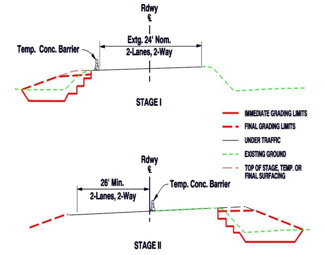
See Figure 5-6 for example Cross Sections for “Stage I” and “Stage II”. Note the multiple line
styles shown – representing existing and future surfaces – simultaneously on a single diagram.
April 2021 Page 218Oregon Department of Transportation
Traffic Control Plans Design Manual
Figure 5-6: Cross Section Example
Plan Sheets
Using the earlier base sheet and cross section information, the TCP incorporates the desired
staging and phasing into the design. Designers should graphically identify the work area –
typically accomplished by filling in the area with a stippling hatching pattern. Areas “under
traffic” can be left unchanged. Other areas, such as “Construct under Traffic” should use a
distinct alternate hatching pattern. Example patterns are shown in Figure 5-7.
Figure 5-7: TCP Stippling Hatching Patterns
Complete the plan by including the required TCD within each Stage and Phase.
April 2021 Page 219Oregon Department of Transportation
Traffic Control Plans Design Manual
Typical Applications
Include the appropriate Standard Drawings to provide additional guidance and details for the
more straight-forward or common work activities. To determine which Standard Drawings to
include, Designers should carefully evaluate the following:
Scope of work.
Duration of the project.
Existing roadway characteristics – Type, widths, location, features, geometry.
Proximity of work to live traffic.
Traffic volumes.
Pre-construction posted speed.
Refer to Chapter 4 – Specifications for detailed discussions regarding Standard Drawings and
Standard Details.
Chapter 6 of the MUTCD also contains a number of common traffic control layouts for
standard work zone operations. Refer to Section 6H – Typical Applications for a variety of more
common layouts for activities ranging from mobile operations to long-term stationary work on
freeways. Designers can use the Typical Applications to develop more detailed, project-specific
TCPs, as needed.
April 2021 Page 220Oregon Department of Transportation
Traffic Control Plans Design Manual
Temporary Sign Design
Temporary Signs
Use the following resources when determining the text, configuration, sizing, color, usage and
placement for Temporary Signs:
ODOT “Sign Policy & Guidelines for State Highway Signs”
FHWA “Standard Highway Signs”
FHWA “Manual on Uniform Traffic Control Devices (MUTCD)”
GuideSIGN ™
For the design of highway signs, ODOT utilizes a software program called GuideSIGN™. The
program runs within the MicroStation™ drafting software environment. It is also available in
AutoCAD™ and there is a Windows® version.
The program includes a variety of features for creating many panel styles derived from
MUTCD sign standards. Designers should become familiar with the features of the software by
completing an on-line tutorial or taking a training class. GuidSign™ can be a powerful tool in
designing permanent and temporary signs for your project. However, its complexity may
warrant a grief amount of training before beginning your designs.
Once in the software, Designers can manipulate a variety of sign panel categories to create
needed signs. Example categories include:
Panel (Regulatory, Guide, Service, Exits).
Borders (Thickness, radius, offset).
Margins (Border, Text, Symbols, etc.).
Spacing (Letters, Words, Symbols, Shields, etc.).
Text (Font style, Height, Orientation).
Symbols (Arrows, Logos, Shields, etc.).
Figure 5-8: GuideSIGN™ Example
April 2021 Page 221Oregon Department of Transportation
Traffic Control Plans Design Manual
Sign Design
When using GuidSign™ (or other applicable software) to design temporary signs, details
shown in Table 5.2, below, should be used.
Table 5-2: Sign Design Attributes
SIGN SIZE BORDER RADIUS BORDER THICKNESS BORDER INSET
(in x in) (in) (in) (in)
< 24 x 24 1-1/2 5/8 3/8
30 x 30 1-7/8 3/4 1/2
36 x 36 2-1/4 7/8 5/8
48 x 48 3 1-1/4 3/4
60 x 72 3 1-1/4 3/4
72 x 120 1/8 x Min. Dimension 1-3/4 1-1/4
> 72 x 120 1/8 x Min. Dimension 2-1/2 2
In GuidSign™, various text fonts, height, and spacing are selected for letters, numbers, and
fractions. Others objects – arrows and symbols – can be selected from the menus. GuidSign™
also includes a feature for placing Exit Panels within a sign design. There are editing functions
for modifying the sign and moving and aligning objects and text. Once the sign is prepared,
panel dimensions can be added. A reporting function can be used to prepare a detailed sign
panel report as shown in Figure 5-9. Sign contractors and sign shop can then use the report to
manufacture the sign.
April 2021 Page 222Oregon Department of Transportation
Traffic Control Plans Design Manual
Figure 5-9: Sign Panel Report Example
April 2021 Page 223Oregon Department of Transportation
Traffic Control Plans Design Manual
Drafting Standards
ODOT provides a number of resources for the development of highway construction contract
plans. The tools are available on the ODOT website under the Roadway Engineering page.
Users can search the internet for “ODOT Drafting and Contract Plans Program” to find the
Roadway Engineering home page. The most commonly used resource is the ODOT CAD
Manual and the ODOT CAD Workspace.
ODOT CAD Manual
The ODOT CAD Manual presents the policies, procedures, methods, and standards for
developing and preparing final Contract Plans. It also provides the standards used in the
preparation of these plans using Computer Aided Design (CAD) in MicroStation™.
Department staff, consultants, and outside agency personnel should use the CPDG to prepare
contract plans.
ODOT staff and consulting engineer staff working on ODOT projects must perform road design
services and contract plan production using MicroStation™ and InRoads™ and provide all
deliverables in a form suitable to these programs.
Consultant engineering staff working on federal aid projects for local governments is
encouraged to follow the direction in this guide as closely as possible. Other CAD formats may
be required as a part of a contract with a local government.
ODOT CAD Workspace
The CAD Workspace is a FTP (File Transfer Protocol) website that maintains several files useful
for developing ODOT construction contract plans. Under the ODOT Workspace, Designers can
download, install and update the following tools:
Cell Libraries
The TCP cell library – “TCPE.cel” – can be used to quickly place TCP related signs, devices, and
symbols on traffic control plan sheets.
TCP Cache
The TCP Cache is another useful resource in developing traffic control plan. Once the
MicroStation™ compatible cache file is attached – “TCP.cache.dgn” – the elements
within the file can easily be copied into the plans. Although not listed under the ODOT
Workspace, contact the Traffic Control Plans Unit for a copy of the TCP cache file.
April 2021 Page 224You can also read