RESEARCH AND ANALYSIS OF GEOSYNTHETICS FOR A TAILINGS STORAGE APPLICATION
←
→
Page content transcription
If your browser does not render page correctly, please read the page content below
RESEARCH AND ANALYSIS OF GEOSYNTHETICS FOR A TAILINGS
STORAGE APPLICATION
                       1                      2                3
Marc, AMTSBERG , John, BUCKLEY , Chris LANE
1
 Sector Manager Mining, Geofabrics Australasia, Gold Goast, Australia, : m.amtsberg@geofabrics.com.au
² Business Development Manager SFL Piletech, Gold Coast, Australia, jbuckley@sflpiletech.com.au
³2LMGSPL, Perth, Australia, lmgspl@bigpond.com

This paper describes the benefits of using performance based geosynthetic testing for a
copper-gold tailings storage operation in South Australia. This particular location requires
strict environmental controls in a sensitive environment. Consultation occurred early during
the approvals process to provide geosynthetic design guidance on the tailings storage facility
site and design which had been selected. The regulatory requirements had two aims. The
first was to provide a primary under-drainage collection system and the second was to
provide a low permeability barrier in the form of a clay liner or geomembrane.

In the preliminary design stage of this tailings storage facility, technical issues were
addressed through a number of options. Refinement of the options and selection of the final
option required a project specific testing regime to demonstrate its effectiveness.

The selected option comprised a double HDPE geomembrane with a tri-planar drainage
geonet as a leak detection system. The over-drainage on the top liner comprised another tri-
planar drainage geonet overlain by a geotextile in order to meet flow requirements. The tri-
planar HDPE geonet was internally reinforced enabling in-plane flow rate to be maintained at
high compressive loads. A thorough evaluation of the proposed tailings storage under-
drainage and lining system was carried out in order to establish an equivalent or superior
performance to the original design alternatives. The relevant evaluation analysis included:
    1. Filtration testing using a modified Gradient Ratio test
    2. Hydraulic analysis and performance assessment of the proposed design profile for in-
       plane flow at normal pressures up to 1000kPa under long-term conditions
    3. Detailed performance analysis of the geonet, geotextile, and geomembrane interfaces
       under high normal stress

The use of geosynthetics in primary tailings drainage systems must be a design-for-function
process as index specifications do not address the range of performance criteria found
onsite. Geotextiles must consider clogging potential for each tailings medium as segregation
risk and precipitation properties may have an unwanted influence on filter performance.
Geosynthetic performance testing should be considered early in the project design stage. A
robust testing regime can be a key part of the approvals process providing the client with
design alternatives that consider and control engineering risk and project economics.

Keywords: Geonet, Geotextile, Geomembrane, Drainage, Filter, Tailings

    Presented at the 7th International Congress on Environmental Geotechnics,
                       Melbourne, Australia, November 2014
                                                                                                        1
1 INTRODUCTION
The site is located in the Mount Lofty Ranges, 55 kilometres southeast of Adelaide, South Australia.
The mine is located within the catchment of the Murray River and is therefore located in a sensitive
environment. The project is situated within the Kanmantoo Trough, which is an axial zone hosting
numerous former base metal and copper-gold mines and has been the subject of sporadic mining
activity of both vein and replacement style deposits since the mid 1800’s. A mine previously operated
at the site from 1970 to 1975 when mining ceased and the mine was placed on care and maintenance
in 1976. The mine produced a total of 4.1 million tonnes of copper ore. Operations ceased due to low
copper prices, a high exchange rate and increasing costs. In April 2004 another company acquired
the mining lease and commenced exploration of the deposit and undertook various studies to bring the
project into production.
The selected style of tailings storage facility (TSF) for the new project was an integrated waste
landform (IWL), one of the options examined as part of an initial scoping study. The IWL is simply
defined as a tailings storage facility (TSF) that is located inside the waste rock storage. It is formed by
placing controlled, compacted, earthworks to form a containment embankment to retain the tailings.
Mine waste is placed around the outer edge of this containment embankment such that a void is
formed inside the storage. This void allows for further controlled, compacted, earthworks around the
circumference of the void to form a perimeter containment boundary between the tailings and the mine
waste.
Prefeasibility studies for a number of waste storage options and configurations had been undertaken
prior to the selection of the final site. The site selected for the IWL was based on consultation
between representatives of the Mining Company and representatives of Primary Industries and
Resources South Australia (PIRSA). The site required a lined Tailings Storage Facility (TSF) to store
both tailings and waste rock that met regulatory lining requirements and maximised water recovery.
Initially 1.75m thick of compacted clay and a herring bone panel pipe drainage system was considered
for the base of the TSF. Containment embankments comprised compacted clay with a horizontal width
of 5m. However it was determined that a geomembrane lined facility with a leak detection system
would better serve to meet regulatory requirements.
Certain unknown Geosynthetic properties manifested during the design process, focussed on the
impact of confining pressures up to 1000kPa on the drainage and lining system, and the impacts of
fine grade tailings on the geotextile filters making up part of the drainage system. It was the design
intent to establish test values of the specific Geosynthetics under as many project conditions that
could be replicated in the laboratory to provide design values and Safety Factors to establish a better
understanding of long term performance of the filters, drainage and lining system.
2. DESIGN OPTIONS
2.1 DESIGN OPTION 1
The initial design option presented to the regulators in October 2007, comprised compacted clay liner
of 0.75m over insitu clay of 1.0m (a total thickness of 1.75m) with a primary drainage system
consisting of herring bone panel drains. The construction risks for this proposal included volumes of
suitable clay available for construction, economics of sourcing clay from a number of borrow sources
identified around the site and construction quality control and the survivability of the clay liner during
construction and operation. Design questions included the potential for blinding of the geotextile
materials wrapped around the underdrainage pipe and the granular filter in which the underdrainage
pipe was to be placed and ability of the proposed drainage systems to perform under the extreme
loads of 55m of tailings (1000kPa).
2.2 DESIGN OPTION 2
The construction and operation risks of Option 1 for a compacted clay liner resulted in the
development of the next option which comprised 1.5mm HDPE geomembrane liners in lieu of the
compacted clay. The design comprised a double HDPE liner with a flownet leak detection layer over
the base area likely to be flooded by the design storm event, and a single HDPE liner over base areas
2unlikely to be flooded by the design storm event. A primary underdrainage drainage system similar to
the design for Option 1 was retained for Option 2. Further questions were raised based around
mitigation of liner damage during construction of the underdrainage system. A layer of crusher dust
waste was proposed as the material to enable the surface of the liner to be trafficked during
construction. Sourcing of the crusher dust materials and construction risks posed challenges in terms
of cost and constructability.
2.3 DESIGN OPTION 3
The construction risks associated with Option 2 resulted in the same liner profile with the primary
underdrainage system replaced with a flownet and geotextile filter. Laboratory testing designed to
replicate project parameters was carried out at the Geosynthetic Centre of Excellence. Testing
included suitability and direct comparisons between the panel drain system and a drainage geonet for
primary drainage performance. Potential geotextile damage and the impacts of the geonets in terms of
strain values transferred to the geomembranes were tested under 1000kPa to ensure liner integrity
under long term normal stresses. A selection of geotextiles were tested in direct contact with both full
Tailings samples and segregated fine samples, to establish clogging and retention potential.
The testing led to the final design for construction of a lower specification 300mm clay layer with a
5mm triplanar geonet sandwiched between 2mm HDPE geomembranes to serve as leak detection.
The primary drainage collection system consisted of a 5mm triplanar geonet with a select nonwoven
needle punched polyester geotextile in intimate contact with the tailings media.
3. LABORATORY TESTS AND DISCUSSION
3.1 FILTER PERFORMANCE TESTING
3.1.1 TEST SUMMARY
Both the panel drain and geonet design would rely on filter performance of the upstream Geotextile in
terms of a balance between particle retention and prevention of clogging of the drainage system. The
immediate advantage of the geonet system over a pipe wrapping was increased surface area of the
filter geotextile that could allow direct placement of the tailings medium. The key question was whether
filter performance would be achieved with a tailings medium with full fraction under 600 microns and
15% under 75 microns, with segregation potential upon deposition that would require consideration
(Palmeira et al 2010). The concern with the incorporation of a geotextile filtration layer is threefold:
a. the geotextile would clog preventing flow of liquor into the drainage system
b. the pore size of the geotextile exceeded that of tailings and a significant fraction would be
carried through the geotextile into the geonet, clogging this system.
c. while passing a certain tailings fraction, piping and instability would occur in the tailings
upstream.
Tailings properties tested comprised whole of tailings (sand and silt with minimal clay) and a fine
tailings fraction (Alternate Testing
An alternative test method was adopted where the tailings samples were placed in a constant head,
fixed wall permeameter where system permeability, hydraulic gradients and fines loss through the
geotextile could be measured. The testing apparatus was modified to reflect the actual conditions on
site with intent that the process and results would be evaluated independently.
.
3.1.2 FILTER TEST RESULTS
Initially three different tests were conducted at varying moisture contents; 0%, 40% and 60%.The first
two methods of placement (0% and 40% moisture content) were considered to be in variance with
actual site conditions and both applications resulted in behaviour in the tailings which raised questions
regarding validity of any results. The unusual behaviour was as follows;
the 0% moisture content test resulted in sink holes forming over the surface which formed
preferential flow paths through the material
the 40% moisture content test had noticeable air-pockets within the tailings structure
The procedure which most accurately reflected the conditions on site involved pre-hydrating the
tailings to a moisture content of 60% such that material would flow into the test apparatus and settle
naturally before a head was applied. During initial testing, measurements were taken with regard to
permeability, hydraulic gradient and most crucially fines passing for two non-woven geotextiles. The
behaviour of the tailings sample was observed and the notable observations were as follows;
fines passing peaked during tailings placement and reduced to zero after 24-72 hours;
at the interface between the top surface of the tailings and the water a layer of super saturated
gel like material formed. This gel appeared very rapidly during settlement post disturbance of
the sample, was highly bonded and confined to the upper most layer of the tailings where
there was limited self-weight confinement.
After the testing was completed for fines retention the tailings sample was vacuum excavated to
evaluate the permeability of the sample at different thicknesses. While doing this the sample would be
disturbed, but once completed the gel layer reformed very rapidly each time. This layer appeared to
comprise the finest fraction of the tailings and appeared to control the permeability of the system.
3.1.3 Fines Retention Results
Fine Tailings Passing Results
20
Fines Passing (g/m2)
15
10
5
0
0 20 40 60 80 100 120 140
Time (hours)
A39/60%/Whole A34/60%/Whole A39/60%/Fines
Figure 3.1 Results for whole tailings sample and fines(was less than 50mm, system permeability was increased by an order of magnitude, indicative of a
coarser fraction formation within this zone above the geotextile.
1.00E-04 1.0E-05
k (m/s)
System Permeability (m/s)
1.00E-05
1.0E-06
1.00E-06
0 50 100 150
Time (hours) 1.0E-07
0 100 200 300
-63 A39 60% Whole A39 60%
Sample Length (mm)
Whole A34 60%
Figure 3.2 – System permeability A34/A39 Figure 3.3 Permeability vs Sample Length
for A39/Figure 3.4 Hydraulic Gradient Comparisons – A39 Geotextile with Whole Tailings Sample and
- 1.5mm HDPE Geomembrane
- Rigid plate
3.3.2 RESULTS AND DISCUSSION
The analysis program is used to group areas with similar amounts of strain and summarise these
areas as a percentage of the total area, the geomembrane analysis showed that 100% of the Total
Area was maintained under 0.25% strain, meeting the most stringent German landfill criteria.
For geotextile survivability, the maximum deflection observed was 3.5 mm or 3.5kN/m per grid
aperture. When applied with relevant Factors of Safety for Creep = 1.4 (Polyester geotextile),
Installation Damage = 1.1 (Fine grained tailings), Chemical & Biological = 1.0, Design Life = 1.1 (60
years) Structure Class = 1.1 Factored Maximum Load = 6.5 kN/m
Geotextile Wide Width Tensile Strength = 21.0 kN/m (A39 MARV Value=97.5% confidence level)
The overall SAFETY FACTOR for A39 geotextile = 3.2, was deemed appropriate for this application.
3.4 LABORATORY TESTS TO ANALYSE DRAINAGE PERFORMANCE
3.4.1 DRAINAGE TESTING
In plane flow rate testing was carried out on biplanar and triplanar geonets to ASTM D4716-08 which
can be both an index test and a performance based test to site stresses, hydraulic gradients and
include observation of multi-layer systems. The intent was to test both biplanar and triplanar geonets
of varying mm thickness and;
1) Establish first a direct laboratory comparison for planar flow from the MQA testing carried out in
Europe to the Australian laboratory. This was confirmed for data up to 500kPa.
2) Ensure that the planar flow values would meet volume requirements of the Tailings Facility.
3) Test the impact of each Geosynthetic under the same normal stress and hydraulic gradient. By
introducing each layer and testing each component both separately and with the full project
profile under 1000kPa, a planar flow Reduction Factor for each component could be established
and linked to factors applied in desktop design.
As this testing was conducted in conjunction with initial strain testing outlined, the test focus was
narrowed to a triplanar Geonet. Initial testing was carried out under normal pressure of 800kPa and
1000kPa to establish the “linear” relationship at varying stresses assumed during an index design.
This data confirmed survivability and provided indication as to short term creep that may occur in the
system. Testing between rigid plates was then directly correlated to testing between 1.5mm
geomembranes that indicated a 5mm triplanar net would perform adequately as a “leak detection”
drainage system compared to the design flow requirements of 1000m³/day.
Further testing was designed to replicate the project profile, and provide insight as to the reduction
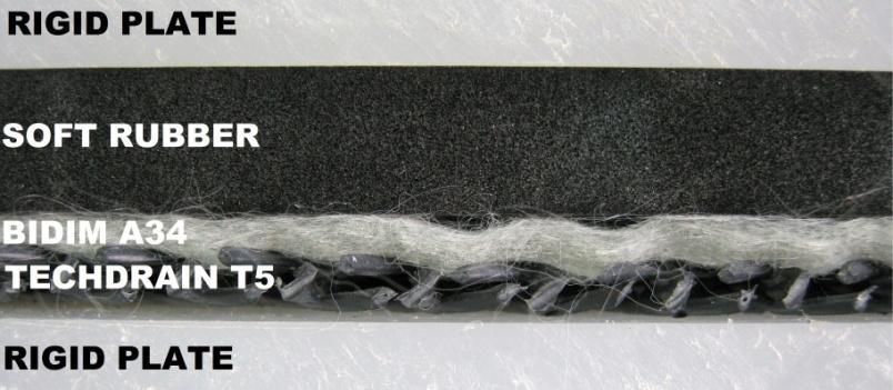
factors that should be applied to the overall design. The full project profile was set up between rigid
plates. Due to the problems associated with placing actual tailings in the rig, soft and hard rubber
boundaries were used to mimic the tailings medium in the profile. These were underlain by the non-
laminated non-woven needle punched A39 geotextile above the 5mm triplanar net and rigid plate. The
composition of the tailings meant that chemical and biological clogging would not expect to occur and
overall Creep of the geonet and geomembranes, and creep and intrusion of the geotextile would
provide the primary factors for flow reduction. Using a non-laminated geotextile meant that maximum
geotextile intrusion would occur, providing an element of conservatism to the results. Conservative
reduction factors for both intrusion and creep were then applied in desktop analysis to tested results.
7Figure 3.5 – Primary Drainage Profile with “Soft Rubber”Tailings"
3.4.2 DRAINAGE DISCUSSION AND RESULTS
The entire TSF area was split into 6 sub-catchment areas based on the location of ridge lines and the
extremities of the TSF. Planar flows were established for each sub-catchment at the required hydraulic
gradient and added up to establish total flow capacity for the TSF. Based on the design layout of the
central collector pipes the drainage net capacities were expected to be in the range of 1,473/day to
3
2,147m /day so the use of 5mm triplanar geonets was deemed a feasible drainage option based on
the following assumptions:
a. Design Normal Pressure – 1,000 kPa
3
b. Design Flow Volume – 1,000 m /day
c. Megaflo under-drainage and Megaflo pipes replaced by triplanar 5mm Geonet
d. Central Collector Pipes retained in design
e. An additional collector pipe within sub-catchment A1, to maintain Factors of Safety due to the
very flat gradient of this sub-catchment
f. Long-term Reduction Factors for Chemical & Biological Clogging = 1.00 – from assumption of
saturated conditions provided and the presence of a downstream airlock to prevent air entry
into the underdrainage system
g. The Long-term Reduction Factors for Intrusion & Creep are as follows:
a. Max. Drainage Net Capacity, RFin = 1.5 & RFcr = 1.4; (RFcc and RFbc = 1)
b. Min. Drainage Net Capacity, RFin = 1.8 & RFcr = 1.7;
c. Above from Koerner, Koerner (2005).
A key benefit of testing the non-laminated geotextile in this case developed during construction review
considerations in that the laboratory had real-time data on the long-term UV stability of the geotextile
beyond 6 months, allowing for certain freedoms to expose the geotextile during construction.
4.1 CONCLUSION
Geosynthetics are being used in tailings dam applications that require extreme performance criteria
often not documented in typical design procedures. These include challenging chemistry, very fine
materials and extreme load scenarios. This can present significant design risk to the client, designer
and regulatory body. This project outlines that if a design for function approach is adopted, it allows
both established and modified testing regimes to demonstrate performance criteria under site
conditions. This can lead to better design practice and overall cost savings for the client.
ACKNOWLEDGEMENTS
The contribution of the following must be acknowledged by the authors;
Professor Jonathan Fannin PhD, P.Eng – University of British Columbia
Emeritus Professor Robin Fell – University of NSW
Ian Peggs – PHD, P Eng – Icorp International
REFERENCES
Hornsey WP, Wishaw DM 2012. Development of a methodology for the evaluation of geomembrane strain and relative
performance of cushion geotextiles – Geotextiles and Geomembranes 35 (2012) 87-99
Koerner RM 2005, Designing With Geosynthetics, 5th Edition. Prentice Hall USA
Palmeira EM, Beirigo EA, Gardoni MG, 2010.Tailings non-woven geotextile filter compatibility in mining applications –
Geotextiles and Geomembranes 28 (2010) 136-148
8You can also read