Medical dosimetry using Optically Stimulated Luminescence dots and microStar readers
←
→
Page content transcription
If your browser does not render page correctly, please read the page content below
Medical dosimetry using Optically Stimulated Luminescence dots and
          microStar® readers
          Christopher A Perks*a, Cliff Yahnkeb, Marc Millionc
          a
            LANDAUER EUROPE, Unit 28, Bankside, Station Approach, Kidlington, Oxford, OX5 1JE,
          United Kingdom.
          b
            Landauer Inc, 2 Science Road, Glenwood, 60425 IL, USA.
          c
            LANDAUER EUROPE, 33 Avenue du General Leclerc, F-92266, Fontenay-aux-Roses
          CEDEX, France.

Abstract. Landauer has developed a portable dosimetry system based on its Optically Stimulated Luminescence
(OSL) technology. It is called the microStar®, and its core technology is the same as that in its personnel monitors
used throughout the world (more commonly known by their trade names, Luxel®, and InLight®).

OSL using aluminium oxide doped with carbon (Al2O3:C) has been used extensively for personal radiation
dosimetry for many years. It has the advantages of low detection threshold and re-analysis. Recently, single dots
of OSL material and a portable reader have been developed with a view to medical applications. A number of
organisations asked to make trials of this system.

The acceptance of this system has grown worldwide with recent trials at various hospitals in France, the USA and
the UK. Most recently, the IAEA has undertaken a Coordinated Research Program (CRP) to identify dosimetry
systems for use in developing countries.

The trials, some of which have already been reported in the scientific literature, have included studies of the
energy and dose response, the stability of the readout and the overall accuracy of the measurements as compared
to other systems used in patient dosimetry. It is evident that the OSL system is capable of achieving the high
degree of accuracy required for medical applications (reproducibility (< 2%)) and has a number of advantages
over current methodologies such as a wide dynamic range (0.01 mGy to 15 Gy) and negligible energy, angle, dose
rate, and temperature dependence. In addition, one unique feature relative to TLD’s is the ability to re-read the
dose many times (with potential application for archiving the dosemeter with patient records) as only a fraction of
the stored charged is consumed in each analysis.

This paper will review the results of these trials highlighting similarities and differences. Where differences were
found, possible explanations will be presented. The overall properties of the system will be summarised drawing
out the advantages and disadvantages over current systems (TLD, MOSFET and Diode dosimetry). In the light of
the experience with these trials, new developments of the system will be presented.

KEYWORDS: Optically Stimulated Luminescence, microStar, patient dosimetry.

1      Introduction

The application of optically stimulated luminescence (OSL) for dosimetry has been reviewed
previously [1]. Landauer has developed the application of aluminium oxide doped with carbon
(Al2O3:C) as an OSL detector material for its external personal radiation dosimetry services [2-6]. It is
currently Landauer’s preferred method because of a number of key operational and technical features:

      •       high sensitivity, improving low dose precision and enabling thin layer dosemeters;
      •       elimination of heating permits more possibilities for the design of dosemeters, including:
              powder coatings on clear film bases; simpler and more reliable analysis instrumentation; and
              better control over the amount of luminescence emitted;

*
    Presenting author, e-mail: cperks@landauer-fr.com
                                                                                                                1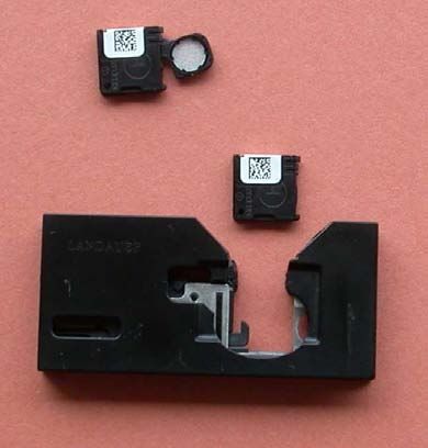
•    re-analysis of dosemeters is possible as less than 0.25% of the stored charge is consumed in
           each analysis.

Landauer have recently developed a new system, called InLight® [2], based on modified Panasonic
dosemeters and readers. In addition, we have developed a small, manual reader, called microStar™,
able to read-out small dots of our OSL detector material. This extends our range of application into
medical and other fields where single point measurements are required.

This paper describes the microStar system, outlines the principal characteristics of the system and
some trials of the system.

2     The microStar system

The microStar system comprises dosemeters, which may take the form of conventional personal
monitoring dosemeters or individual dots, and a purpose designed reader, as described below.

2.1       Dosemeters

As its detectors, Landauer use aluminium oxide doped with carbon (Al2O3:C). The aluminium oxide,
Al2O3:C, used in our dosemeters is produced at the Landauer Crystal Growth Facility in Stillwater,
USA. Al2O3:C (corundum or sapphire) is used primarily because of its high sensitivity to radiation
(40 – 60 times that of LiF (TLD-100)). It has a principal emission peak at 410 – 420 nm (blue). It also
has excellent properties for radiation dosimetry, including linear response up to 300 cGy. Al2O3:C
powder is obtained by grinding crystals and sifting the powder to the desired size range. This powder
is mixed with a polyester binder and coated onto a roll of polystyrene film. The aluminium oxide
layer is approximately 0.2 mm thick sandwiched between polyester foils 0.03 mm thick (top) and 0.1
mm thick (bottom). The film roll is subsequently cut to the desired shape and size (for InLight
dosemeters and dots this is discs approximately 5 mm diameter). In commercial applications these
discs are either inserted into Panasonic type dosemeters or small holders for individual dots.

Figure 1: OSL strip and dosemeters.

2.2       Reader

A number of methods have been developed for analysis of the OSL from Al2O3:C detectors, including
the pulsed optically stimulated luminescence method adopted for Landauer’s Luxel badges [4].
However, in the InLight system, Light Emitting Diodes (LED) emitting light at a wavelength of 532
nm (green) are used as the light source. These offer several important advantages over traditional
thermal stimulation systems (TLDs). In particular, they are inexpensive, robust and compact, enabling
the readers to be much more reliable (by eliminating high temperatures, combustion, external gas
2
supplies, etc). The LED based readers can therefore achieve much higher precision and repeatability.
The InLight system utilises an array of 36 LEDs; all 36 (strong beam) are illuminated for low dose
exposures and only 6 LEDs (weak beam) are illuminated for high dose exposures. A pre-test under the
dosemeter’s open window determines the LED strength required.
A number of readers are available, including fully automatic readers for reading up to 500 dosimetry
badges in a single process.
The microStar reader is a small, portable reader, capable of reading out personal monitoring
dosemeters or dot detectors. This was designed for a variety of applications, including medical
dosimetry. The microStar measures approximately 30 x 20 x 10 cm and weighs approximately 15 kg.
It uses a conventional electrical power source (110 – 240 V, 1.5 amp, 50 – 60 Hz) and no other
connections. It is therefore a ‘plug-in and operate’ piece of equipment.
To control and monitor the operation, microStar has a dial and two indicator lights. The reader
connects via a USB cable to an external computer that controls the setup, analysis and data recording.
Quality control (QC) procedures to ensure accurate dose results include: the measurement of a low
intensity light photon source calibration standard; dark current and LED intensity; the ability to
calibrate to any set of reference conditions; and the use of quality control dosimeters for periodic QC
testing. The frequency of quality control procedures is user defined and depends upon the desired
accuracy. For normal measurements (bias < 5%), calibration is needed once a month or after
transport.
Figure 2: The microStar reader
3 Characteristics of the system
In medical dosimetry, there are a wide range of clinical conditions (e.g. technique, energy, angle, dose
rate, etc.) which require the user to have a very thorough understanding of their dosimetry system and
how it performs in these various environments. This translates into a series of correction factors
which are typically applied by hand after the measurement has been made. So, while electronic
devices such as diodes and MOSFETs provide instantaneous output, it is entirely possible that an
accurate measurement may require minutes or hours of post-measurement analysis, or a knowledge of
the exposure conditions that is not practical (e.g. irradiation angle during an IMRT treatment).
3Landauer’s microStar system provides two different solutions to this problem. On one hand, the
reader is flexible and can be calibrated to any set of reference conditions. These calibrations can be
individually stored and recalled at a later time as necessary. At the same time, the dosimeter itself is
virtually invariant with energy, angle, dose rate, etc. in the radiotherapy environment. This eliminates
the need for post-measurement correction factors and allows a medical technician rather than a
medical physicist to perform the measurement.
These advantages will be described in further detail using data from published sources as necessary.
3.1 Energy response
In this section we describe the energy dependence, dose-response, and accuracy of measurements
made with OSL dot detectors read out using the microStar reader.
3.1.1 Radiotherapy fields
For radiotherapy the energy range of interest is for 60Co (mean energy 1.250 MeV) upward to 20 MeV
using both photons and electrons. The on-phantom response at these energies is about 3 times less that
the response at 48 keV. Figure 3 gives the energy response for the dots over the radiotherapy range [7,
8 and 9]. It can be seen that the energy response typically varies by less than 4 % over this range. If
one further considers only the output from a linear accelerator (ignoring Co-60), this variation is
reduced to 2% or less. This allows a technician to use a single calibration for all clinical conditions.
In the event that the user does not record the exposure energy, the readings are still valid. For those
cases where even greater precision is desired, the microStar is flexible enough to be individually
calibrated to each particular field.
Figure 3: Energy response in the radiotherapy range [7, 8 and 9].
1.04
1.02
Relative response
Viamonte (photons)
1
Jursinic (photons)
0.98 Jursinic (electrons)
Schrembi (photons)
0.96
Schrembi (electrons)
0.94
0.92
0 5 10 15 20
Energy /MV
Shembri and Heijmen [7] noticed a difference of 3.7 % in the response between the photon and
electron beams. There is also a significant difference for 18 MV photons between the results for
Viamonte et al [9] and Schembri and Heijman [7]. The reasons for these variations are not yet
understood and indicate the need for a careful understanding of the measurement protocol used before
comparing the results.
43.1.2 Mammography, diagnostic and CT fields
With an effective Z of ~10, the Al2O3:C detector material will over-respond to the x-rays typically
found in diagnostic applications. The expected energy range for these exposures is from 20 kVp
(mammography) to 120 kVp (Computed Tomography (CT)). The energy response of the OSL dot
detectors has been determined [10] both for exposures on phantom (30 x 30 x 15 cm PMMA) and free
in air for energies in this range and is shown in Figure 4. To minimize the measurement bias of this
effect, Landauer supplies a set of calibrated dot dosemeters. These calibrates are created using an
80 kVp Philips Industrial x-ray generator with a 2.5 mm filter of Al (2.9 mm Al HVL) with the
dosemeters exposed on a PMMA phantom. The energy response given in Figure 4 is normalized to
this exposure condition.
Figure 4: Energy response of dot detectors in mammography, diagnostic and CT fields [10]
1.2
1 On Phantom
Free air
Relative response
0.8
0.6
0.4
0.2
0
0 20 40 60 80 100 120
Energy /keV
Using this set of reference conditions, a minimal correction factor (Table 1) can be applied to
measurements made for mammography, fluoroscopy, and CT. These correction factors can be directly
entered into the microStar, effectively creating a separate calibration which can then be applied as
necessary.
Table 1: Correction factors for mammography, fluoroscopy and CT.
Computed
Calibration Mammography Fluoroscopy
Tomography
Set (~32 kVp) (~80 kVp)
(~120 kVp)
80 kVp* 1.39 1.00 1.12
* 80 kVp Philips Industrial x-ray generator with a 2.5 mm filter of Al (2.9 mm Al HVL)
Again, the flexibility of the microStar allows the user to calibrate the device to virtually any
environment and achieve accurate results.
53.2 Angular response
3.2.1 Radiotherapy fields
At radiotherapy energies the angular response of the OSL dose detector is uniform from 0 – 360o
incident angles (Figure 5 [8]). This allows the technician to make a measurement without knowing the
exposure angle. This is important for a variety of treatments in which the gantry angle is changed
throughout the procedure.
Figure 5: The angular response of the OSL dot detectors [8]
3.2.2 Mammography, diagnostic and CT fields
At lower energies (relevant to mammography (~ 32 kVp), diagnostic (~80 kVp) and CT (~120 kVp)
fields) the variation (relative to 1 at normal incidence) is within 10% up to incidence angles of 60o.
(Figure 6).
Figure 6: Angular response in the mammography, diagnostic and CT
Horizontal rotation Vertical rotation
1.02 1.02
Response relative to 0 o
Response relative to 0 o
1 1
0.98 0.98
Mammography
0.96 0.96
Diagnositc
0.94 0.94
CT
0.92 0.92
0.9 0.9
0.88 0.88
-80 -60 -40 -20 0 20 40 60 80 -80 -60 -40 -20 0 20 40 60 80
Incident angle /degree Incident angle /degree
3.3 Dose response
The dose response has been determined by a number of authors for a number of photon energies and
irradiation conditions for example Figure 7 [11].
6Figure 7: Dose linearity for dots irradiated with 60Co [11]
25000000
20000000
15000000
Counts 10000000
5000000
0
0 500 1000 1500 2000 2500 3000 3500
Dose/cGy
They find a linear response up to 600 cGy with a slight concavity at higher doses. Similar results have
been found by Jursinic [8], Viamonte et al [9] and Schembri and Heijman [7]. The slight non-linear
response above about 600 cGy is reproducible and several authors have fitted the curve either with a
two linear equations covering different regions [11] or by a simple linear-quadratic equation [8].
Schembri and Heijmen [7] also examined the dose rate response up to 6 Gy per minute finding that all
the results were within 1 %.
Jursinc [8] found that the deviation from linearity became measureable at 300 cGy. This response is
predictable and the microStar provides its users with the ability to fit a second-order polynomial to
address this non-linear response. Additionally, a user could simply calibrate the device over a more
narrow range tailored to their clinical conditions (e.g. 100-300 cGy for 200 cGy dose fractions).
4 Trials undertaken
A number of trials have been undertaken with the OSL dot system, some of which have been reported,
and others are at various stages of completion. We have restricted the comments in this paper to those
trails which have been reported. These include with Erasmus MC [7], West Michigan Cancer Center
[8] and IAEA [9].
5 Comparison with other methodologies
Other existing methods used in radiotherapy and medical applications include the use of ion chambers
TLD, diodes and MOSFETs. A number of the trials undertaken with the OSL dots have compared the
properties of these devices and commented on the relative advantages and disadvantages.
Viamomonte et al [9] note that the use of TLDs is often considered as a complex read-out process
involving heating and annealing which precludes instantaneous or near instantaneous readout. Diodes,
which are commonly used for in vivo dosimetry, give an instantaneous readout, but their calibration
factor is dependent upon energy, angle, temperature, and dose-rate. MOSFETs dosemeters are largely
free of these drawbacks, but their life-time is limited. Both diodes and MOSFETs and active devices
and their wiring need to be considered.
5.1 Energy dependence
As noted above (Figure 3), the energy response for the OSL dot detectors is relatively independent of
energy in radiotherapy fields. In contrast diodes have a reduction ion response as a function of energy
up to about 10 % in this energy range (see for example Jursinic figure 9 [8]).
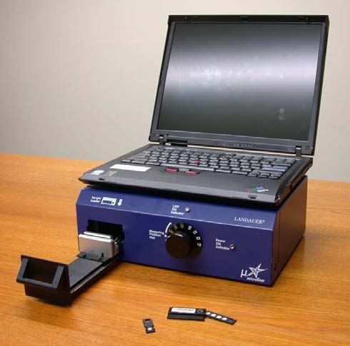
75.2 Angular dependence The angular dependence of the OSL dot detectors for radiotherapy applications is similarly independent of angle. 5.3 Dose response Schembri and Heijmen [7] noted that, in contrast to GafChromic and radiographic films, the response of the OSL dots is linear in the clinically relevant dose range of 1 – 200cGy. 5.4 Stability of the signal Jursinic [8] made some detailed measurements of the stability of the signal as a function of time after irradiation. He found that (with 6 MV there is an initial drop in the signal relative to that measured one minute after irradiation of about 30 %, but that after 8 minutes the signal becomes very stable with a 2% decay from 10 to 3600 minutes. 5.5 Re-readability Jursinic [8] have noted that one particular advantage of the OSL dot dosemeters is that they can be rtead repeatedly with very little loss in signal (0.05% per reading). Combined with the very small long term fading of the signal, this gives the possibility of reading the dosemeter and retaining it for future analysis or indeed as a permanent record of the measured dose (for example attached to patient records). In addition, the re-analysis capability allows for the dosimeter to be repeatedly analyzed, thereby reducing the measurement uncertainty (~1/√n) while eliminating the need for multiple dosimeters in a single measurement (e.g TLD’s). 6 New developments To better accommodate the emerging needs of the medical community, Landauer has recently released a new dosemeter, called the ‘nanoDot’. A picture of this device is shown in Figure 8. Figure 8: The new ‘nanoDot’ and adaptor for readout in the microStar reader. 8
The new dosemeter has the same detector material as previous dots and dosemeters, but in a form
factor 50% of the standard Dot measuring 10 mm x 10 mm x 2 mm. This allows it to be placed in
more restricted spaces such as the eyelid. As with the previous dots an adaptor (also shown in figure
8) has been developed to allow it to be easily read-out with the standard reader and all operations
(exposure, readout and storage) can be undertaken in ambient light conditions.

Future developments will be driven by our increasing understanding of the applications for which the
system is being used. In particular these include the use of the Al2O3 material in stereotactic
measurements where the detector’s extremely high sensitivity allows for very small detectors
(< 1mm diameter).

7     Concluding remarks

The OSL microStar system developed for medical applications could be an ideal tool for radiotherapy
applications. In comparison to TLD, the detectors are identified with individual serial numbers the
can be repeatedly read out enabling them to be archived with the patient record as a permanent record
of dose and can be readout within minutes of exposure. In comparison with electronic detectors
(Diodes and MOSFETs), they require no cabling and are relatively cheap. For radiotherapy
applications the variation in response at different energies and angles is negligible and a number of
authors have noted their suitability for this application, particularly entrance dose. The important
corollary of these features is that the system doesn’t require a medical physicist to operate it thereby
allowing the staff to make more measurements, ultimately improving the quality of care to the patient.
In addition, with the application of small correction factors for the calibration factors, the system is
capable of use in the mammography, diagnostic and CT fields. Such applications include patient
dosimetry and quality control of x-ray beams. Further work is in hand both internally, within
Landauer, and by external trials to more fully validate the system in medical fields and to extend its
range of application.

REFERENCES

[1]    BOTTER-JENSEN, L., MCKEEVER, S.W.S. AND WINTLE, A.G., Optically Stimulated
       Luminescence Dosimetry. Published by Elsevier (2003).
[2]    PERKS, C.A., LEROY, G., YODER, C. AND PASSMORE, C. Development of the InLight™
       Monitoring Service for World-wide Application. In Proc 11th IRPA Congress, Madrid, May
       2004.
[3]    FORD, R.M, HANIFY, R.D. AND PERKS, C.A. Depletion of the signal from optically
       stimulated luminescence detectors. In Proc 11th IRPA Congress, Madrid, May 2004.
[4]    AKSELROD, M.S. AND MCKEEVER, S.W.S. A radiation dosimetry system using pulsed
       optically stimulated luminescence. Radiation Protection Dosimetry, 81 (3): 167 – 176, (1999).
[5]    AKSELROD, M.S., LUCAS, A.C., POLF, J.C., MCKEEVER, S.W.S., Optically Stimulated
       Luminescence of Al203, Radiation Measurements, 29 (3 – 4): 391 – 399, (1998).
[6]    MCKEEVER, S.W.S., AKSELROD, M.S., COLYOTT, L.E., AGERSNAP LARSEN, N.,
       POLF, J.C., WHITLEY, V., Characterization of Al203 for Use in Thermally and Optically
       Stimulated Luminescence Dosimetry, Radiation Protection Dosimetry, 84 (1 – 4): 163 – 168,
       (1999).
[7]    SCHEMBRI, V. AND HEIJMEN, B.J.M., Optically Stimulated Luminescence (OSL) of
       Carbon doped aluminium oxide (Al2O3:C) for Film Dosimetry in Radiotherapy. Medical
       Physics, 34, (6) 2113 - 2118 (2007).
[8]    JURSINIC, P.A. Characterisation of optically stimulated luminescent dosimeters, OSLDs, for
       clinical dosimetric measurements. Medical Physics, 34, (12) 4594 – 4604 (2007).
[9]    VIAMONTE, A., DA ROSA, L.A.R., BUCKLEY, L.A., CHERPAK, A. AND CYGLER, J.E.
       Radiotherapy dosimetry using a commercial OSL System. Medical Physics, 35, (4) 1261 - 1266
       (2008).

                                                                                                      9
[10] HANIFY, R AND SALASKY, M. Single point detector (dot) type testing summary report.
Internal document. (2006).
[11] HOMINICK, J AND SPRINGER, A. Characterisation of OSL dosemeters. MD Anderson,
private communication
10You can also read