Touch and Step Voltage Evaluation based on Computer Simulation for a Mass Rapid Transit System in Thailand
←
→
Page content transcription
If your browser does not render page correctly, please read the page content below
Received: May 5, 2020. Revised: June 8, 2020. 159

 Touch and Step Voltage Evaluation based on Computer Simulation for a Mass
 Rapid Transit System in Thailand

 Chaiyut Sumpavakup1* Kritsada Mongkoldee2 Tosaphol Ratniyomchai2
 2
 Thanatchai Kulworawanichpong

 1
 Research Centre for Combustion Technology and Alternative Energy
 and College of Industrial Technology, King Mongkut's University of Technology North Bangkok,
 Bangkok 10800, Thailand
 2
 School of Electrical Engineering, Suranaree University of Technology, Nakhon Ratchasima 30000, Thailand
 * Corresponding author’s Email: chaiyut.s@cit.kmutnb.ac.th

 Abstract: This article proposed a computer-based simulation approach to estimate touch and step voltages due to a
 lightning strike at a mass rapid transit railway station. A purely resistive circuit model of a station lightning protection,
 and earthing & bonding system is formed in MATLAB/Simulink with Yaek Nonthaburi 1 passenger station of MRT
 purple line in Bangkok, Thailand as a case study. The simulation investigated the consequence of a lightning strike at
 four different locations on the roof of the station and examined whether or not the lightning protection system met the
 standard requirements. The results showed the touch voltages, step voltages and body currents in a steady state together
 with the impact on the human body standing in the station. The simulation can guarantee the effectiveness of the
 proposed model, and also proved that the lightning protection system of the station is able to conform to the standard
 and there is no harm for the passenger in the station.
 Keywords: Touch voltage, Step voltage, Lightning protection system, Mass rapid transit system, Computer simulation.

 railway, for example, in Caulfield to Dandenong
1. Introduction level Crossing Removal Project [3]. Therefore, the
 evaluation of an existing lightning protection is very
 An impact of lightning strikes can create hazards
 important. In [4], a new inspection equipment and a
to persons and installations not only directly by high
 new circuit structure has been developed to evaluate
voltages and thermal effects, but also indirectly by
 and measure both the low-frequency parameter (earth
causing panic and damage to railway safety related
 resistance) and high-frequency parameters (earth
systems. Buildings, bridge, outdoor installations and
 impedance and voltage difference) of the lighting
other structures exposed to direct lightning strikes
 protection performance of earthing system in railway
require an external lightning protection system such
 substation. In addition, in [5] proposed a lightning
as surge arresters [1]. In addition, in [2] proposed an
 disturbance recognition method to recognize the
enhanced efficiency of existing lightning protection
 high-frequency components which cause the relay
based on lightning and surge standard mainly on the
 protection malfunction in the traction substation by
EN series 62305. Internal lightning protection of
 using wavelet energy moment and verified by the
electrical equipment is also required against the
 simulation signals.
danger of damage by over-voltages and partial
 The relevant standards shall be applied for the
lightning currents caused by lightning strikes. For the
 protection of life and property against lightning. For
DC railways, there are risks of metallic corrosion due
 instance, most of the mass rapid transit systems are
to stray current and electrical hazards leading to a
 elevated railways such as BTS skytrain and MRT
danger of passengers and structural damages to the
 purple line in Bangkok, Thailand; as a consequence,
railway station. The earthing and bonding strategy
 the structures of these railways are particularly
developed and implemented for the elevated DC
International Journal of Intelligent Engineering and Systems, Vol.13, No.5, 2020 DOI: 10.22266/ijies2020.1031.15
Received: May 5, 2020. Revised: June 8, 2020. 160

vulnerable to lightning strikes during the storm presents a method of touch and step voltages
season. Another example of the standardization and estimation using a simplified pure resistive circuit
guidance of the lightning protection system was model, i.e. for ease of creating and running the large
required to efficiently reduce the train operation detailed model in a computer software, and uses the
disruptions due to the shutdown of power supply model to estimate the touch and step voltages, and
effected by the lightning strikes in Bogor Station of safety consideration at one of the passenger stations
DAOP 1 Jakarta, Indonesia [6]. The awareness of the of MRT purple line in Bangkok. In other words,
design of the lightning protection is important which another aim of the paper is to check if the lightning
eventually should ensure that fault or lightning protection system of the station satisfies a standard
currents would not impact the equipment and and if the person touching a conductive part in the
passenger in the railway station [7]. station is out of danger from lightning.
 From those reasons of several damages, the This paper is organised into 7 sections. A touch
estimation of touch and step voltages, which is and step voltage calculation method and the impact
another method to assess the lightning protection, due of those voltages to human body according to the
to lightning impulses and the impacts on the human standard are presented in section 2 and 3, respectively.
body in a railway station is paramount. Accordingly, The proposed simulation modelling is described in
the simulation model is needed for the preliminary section 4. Section 5 explains the details and structure
estimation in order to examine the lightning of the study case using one of the MRT purple line
protection system’s compliance with the standard passenger stations in Bangkok. The simulation results
prior to actual operation. are summarised in section 6. The paper is finally
 Several methods involving lightning event concluded in section 7.
simulation such as touch and step voltages, safety
evaluation etc. have been widely studied and 2. Calculation of touch and step voltage
discovered. In [8], an equivalent circuit of a human
 A step voltage is the voltage between the feet of
body was proposed to calculate the touch voltage in
 a person standing near an energized grounded object
the scenario of a lightning strike on a telephone line.
 (lightning flash to the structure). It is equal to the
The body currents were obtained in two simulation
 difference in voltage, given by the voltage
cases: a human holding a telephone and a human
 distribution curve as shown in Fig. 1, between two
standing close to a telephone. The model employed
 points at different distances from the electrode. A
the finite-difference time-domain method (FDTD).
 person could be at risk of injury during a lightning
There is a variety of research in which an
 strike simply by standing near the grounding point. A
electromagnetic simulation method has been
 touch voltage is occurred in the same process as a step
performed to study the electric field intensity caused
 voltage, but the voltage difference being considered
by lightning and also the touch and step voltages.
 exists between the hand and feet.
Unlike the electrostatic counterpart [9], the inductive
 The calculation of the touch voltage can be
effects of lightning on the touch and step voltages can
 performed by using an equivalent circuit in Fig. 2,
be realised [10-12]. The touch and step voltages have
 which is either the Thevenin or Norton equivalent
been studied in many aspects. Suchanek, Hinrichsen,
 circuit. The circuit includes the total body impedance
Brocke and Muller [13] compared four step voltage
 (Zb), the additional resistance for shoes (Ra1) and
limits from different sources, then IEC 60479 [14]
 standing surface (Ra2), and the source voltage (Us)
was chosen for safety consideration. The research
 or the prospective touch voltage (Utp). Surface 1 and
also used 3D FEM simulation to investigate different
 2 denote the standing surface and earth, respectively.
earth termination systems for a rectangular building.
 The effective touch voltage (Ute) is determined by
Nayel, Zhao, He, Cai and Wang [15] studied a more
 measuring the voltage across the series resistance, Zb
accurate method, i.e. by including the modelling of a
 and Ra1. Likewise, the calculation of the step voltage
tower foot as an impedance rather than a pure
 can be done in the same manner as that of the touch
resistance, to calculate the touch and step voltages
 voltage, which is further described in section 4.
around a transmission tower foot. The impact of the
 The total human body impedance for a hand-to-
step voltage on parts and postures of a human body
 hand current path at 50% probability is indicated in
was rigorously researched in [16] using voxel-based
 [14]. By applying the reduction factor r = 0.75 [14],
body models. Apart from the aforementioned
 the total human body impedance for a hand-to-feet
literature, much of the research has only studied the
 current path is obtained in Table 1. In this study, the
touch and step voltages on a substation ground grid
 additional resistances Ra2 and Ra1 are assumed to be
[17, 18] and a simple structure building. To expand
the application of this field of research, this paper
International Journal of Intelligent Engineering and Systems, Vol.13, No.5, 2020 DOI: 10.22266/ijies2020.1031.15
Received: May 5, 2020. Revised: June 8, 2020. 161

 60479- 1 (IEC TS 60479-1:2005) covering the whole
 Energized Grounded Object
 range of shock durations from 0. 1 ms – 10 s. A
 Voltage Distribution Curve unidirectional single impulse current of short
 Step Potential Touch Potential duration, up to 10 ms, may be a source of danger. The
 effects of the impulse currents on human beings and
 livestock are illustrated in IEC 60479- 2 (IEC TS
 60479-2: 2007).
 The specific fibrillating energy Fe for a single
 impulse of the peak current of Ip with the shock
 duration of ti can be determined by the following
 equation.
 Figure. 1 Voltage distribution curve [19] 2
 = × (1)
 Ib
 where Irms is the root-mean-square (rms) value of the
 impulse current ( = /√6).
 Ub Zb The threshold of ventricular fibrillation depends
 on the duration and magnitude of the impulse current.
 Ute The thresholds for the ventricular fibrillation are
 Us=Utp Ra1 shown in Fig. 3 for unidirectional impulses with
 shock duration of less than 10 ms.
 1 The heart-current factor permits the calculation of
 Ra
 the current Ih, as shown in Eq. (2), flowing through
 the paths other than the left-hand-to-feet path which
 Ra2
 represents the same level of danger of ventricular
 2 fibrillation as that corresponding to Iref for the left-
 Figure. 2 Equivalent circuit for the calculation of the hand-to-feet path.
 effective touch voltage [20]

 ℎ = , )2(
150 Ω and 1000 Ω (for old wet shoes with a short-
term condition), respectively. Generally, Ra2 can be
calculated by Ra2 = ρs × 1.5 m-1, where ρs is soil where Iref is the body current for the left-hand-to-feet
resistivity at the standing surface in Ωm. According path. Ih is the body current for the paths given in
to the EN50122-1 standard, body currents, body Table 3. F is the heart-current factor given in Table 3.
voltages and touch voltages as a function of the time
duration in DC traction systems are tabulated in Table 10
2. high risk (more than 50%)
 5
 ms

3. Impact of touch and step voltages on average risk
 (up to 50%)
 human body 2
 Duration of impulsion

 The risk of electrocution due to the touch voltage
is greater than that of the step voltage because the 1
 low risk
passage of the flow of a current is closer to the heart
 0.5 (up to 5%)
region. Fig. 1 depicts the step and touch voltage
gradients near the structure. no risk
 For a given current path through the human body, 0.2
the danger to a person depends mainly on the
magnitude and duration of the current flowing in the 0.1
body. The necessary criterion is the admissible limit 100 1000 10000
of the touch voltage as a function of time. The effects Body current IBrms mA
of alternating current ( 50/ 60 Hz) and direct current Figure. 3 Threshold of ventricular fibrillation for
electric shock on human beings are described in IEC unidirectional impulses [21]

International Journal of Intelligent Engineering and Systems, Vol.13, No.5, 2020 DOI: 10.22266/ijies2020.1031.15
Received: May 5, 2020. Revised: June 8, 2020. 162

 Table 1. Body impedance Zb and body current Ib (Table D.1 in [20])
 a.c. system d.c. system
 r = 0.75 r = 0.75
 Ub Zb(100) Zb(75) Ib(75) Rb(100) Rb(75) Ib(75)
 V Ω Ω mA Ω Ω mA
 25 3250 2438 10 3875 2906 9
 50 2500 1875 27 2900 2175 23
 75 2000 1500 50 2275 1706 44
 100 1725 1294 77 1900 1425 70
 125 1550 1163 108 1675 1256 100
 150 1400 1050 143 1475 1106 136
 175 1325 994 176 1350 1013 173
 200 1275 956 209 1275 956 209
 225 1225 919 145 1225 919 245
 400 950 713 561 950 713 561
 500 850 638 784 850 638 784
 700 775 581 1204 775 581 1204
 1000 775 581 1720 775 581 1720
 Key
 Ib(75) = Ub/Zb(75) × 103 or Ub/Rb(75) × 103 body current in mA Ib(75) body current relating to Zb(75)
 Ub body voltage Zb(75) 75% of the total body impedance
 Zb(100) total body impedance Rb(100) total body resistance
 Rb(75) 75% of the total body resistance r reduction factor

 Table 2. Body currents, body voltages and touch voltages as function of time duration in D.C. traction systems (Table
 D.3 in [20])
 t Ic1 Uc1 Ub,max Ute,max Ute,max
 (s) (mA) (V) (V) long-term (V) short-term (V)
 >300 140 153 120 120 -
 300 140 153 150 150 -
 1 150 160 160 160 -
 0.9 160 167 165 165 -
 0.8 165 170 170 170 -
 0.7 175 177 175 175 -
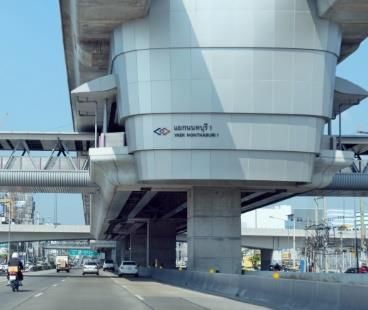
Received: May 5, 2020. Revised: June 8, 2020. 163

Table 3. Heart-current factor F for different current paths
 Heart-current
 Current path
 factor F Air terminal
 Left hand to left foot, right foot or Down Conductor System
 1.0
 both feet
 Both hands to both feet 1.0 Human body
 Left hand to right hand 0.4 Structure to be Concrete
 Right hand to left foot, right foot protected floor
 0.8
 or to both feet Soil
 Back to right hand 0.3
 Back to left hand 0.7 Earth
 Chest to right hand 1.3 terminal
 Chest to left hand 1.5 Figure. 4 Resistive network of the step and touch voltage
 Seat to left hand, right hand or to calculation model
 0.7
 both hands
 Left foot to right foot 0.04
 Thevenin equivalent source Thevenin equivalent source

4. Simulation modeling
 To simulate the touch and step voltages caused
by a lightning strike, a software that allows using
various forms of electrical sources, e.g., AC, DC or
impulse is necessary. The earthing and bonding
model, which is a combination of the air termination
system, the down conductor system and the earth
termination system, is constructed by using a concept
of resistive circuits. This model is energized by (a) (b)
various sources to enable the study of the touch and Figure. 5 Equivalent circuit of the touch voltage
 calculation: (a) touch voltage and (b) step voltage
step voltages simulation. To exhibit the use of
computer modeling and simulation in this scope of
work, MATLAB/Simulink is a tool to perform this of the floor material; this equivalent resistance of the
simulation. floor is incorporated into the Thevenin equivalent
 The model is comprised of the source of resistance. The body current path is left-foot-to-right-
 foot or right- foot- to- left- foot, as a consequence, the
lightning, the resistive network of the structure and a
 resistance of the path includes the body resistance and
human represented by a resistor ( Rb) , see Fig. 4, i. e.
 shoes resistance as shown in Fig. 5 (b), where Ustep
the figure shows a simplified resistive network of the
model. The resistive circuit of the building structure denotes the voltage across two feet.
is obtained by creating an equivalent circuit from the
structure drawings, particularly a given earthing and 5. Case study
bonding drawing. The lightning current is A Yaek Nonthaburi 1 passenger station (S09) of
represented by a current source in which the current MRT purple line in Bangkok, Thailand is a case study
is the peak value of the lightning impulse. The for validation of the simulation model as shown in
Thevenin or Norton equivalent source can be Fig. 6. The resistive model of the station contains the
established from the resistive circuit and the lightning pier (type C1) and the steel structure of the station
current source; this equivalent source replaces the roof; the model is formed according to the structure
voltage source (Us) in Fig. 2, then the final equivalent drawings together with the earthing and bonding
circuit to determine the touch voltage is given as drawings. The diagram showing the composition of
shown in Fig. 5 (a). The Thevenin equivalent voltage the model and the resistive network model of the
( VTH) and resistance ( RTH) are determined by using station are exhibited in Figs. 7-10. The complete
the measuring blocks in MATLAB/ Simulink. In simulation block model built in MATLAB/Simulink
addition to the touch voltage calculation, the is exhibited in Fig. 11.
equivalent circuit for determining the step voltage is
slightly adapted from that of the touch voltage. The
additional structural component is the resistive model

International Journal of Intelligent Engineering and Systems, Vol.13, No.5, 2020 DOI: 10.22266/ijies2020.1031.15
Received: May 5, 2020. Revised: June 8, 2020. 164

 The simulation is broken down into four cases,
 each of which has different lightning strike locations
 at the roof top (air terminals). Fig. 8 also indicates the
 locations of the lightning strike. Two types of the
 lightning impulses, i.e. positive and negative impulse,
 are employed in each simulation case; the impulse
 curves are shown in Fig. 8 with the dotted line
 representing the negative impulse and the solid line
 representing the positive impulse. Even though the
 lightning current is in the impulse form, in this
 simulation only adopts the peak values as a constant
 current source: 100 kA for the negative impulse and
 200 kA for the positive impulse.
 Figure. 6 Yaek Nonthaburi 1 station (S09)

 Roof

 Platform

 Viaduct Viaduct

 Pier Concourse Pier Concourse Pier

 Entrance Entrance Entrance Entrance
 A B C D

 Figure. 7 Internal connection diagram of the simulation model

 Table 4. Input data and system parameter setting
 Parameters Values
 Human resistance for touch voltage calculation 1000 Ω
 Resistivity/resistance of DB25 (A = 490.9 mm2) 0.2385 . (0.486 / )
 0.0168 .
 Resistivity/resistance of bare copper (A=70 mm2 and 120mm2) 0.341 / for 70 mm2
 0.14 / for 120 mm2
 Resistivity of galvanized steel pipe (Ø25mm, 4mm thickness) (A = 263.9 mm2) 0.1 .
 Resistivity of concrete resistance (320 ksc.) 100 .
 Resistivity/resistance of ground rod (Ø16 mm x 3000 mm) (A = 201.1 mm2) 0.0168 . (83.5 / )
 Resistivity of roof (metal sheet), 4mm thickness 0.1 .
 Resistivity of steel plate (40x5mm) 0.1 .
 Resistivity of roof column (Ø406.4mm, 9mm thickness) (A = 11,236 mm2) 0.1 .
 Resistivity/resistance of lightning air terminal (Ø16 x1000 mm) (A = 201.1 mm2) 0.0168 . (83.5 / )
 Resistivity/resistance of copper tape (25x3 mm, A = 75 mm2) 0.0168 . (0.224 / )
 Earthing resistance 0.2 Ω
 positive impulse = 200 kA
 Peak of lightning surge current (class I: IEC62305-1)
 negative impulse = 100 kA

International Journal of Intelligent Engineering and Systems, Vol.13, No.5, 2020 DOI: 10.22266/ijies2020.1031.15
Received: May 5, 2020. Revised: June 8, 2020. 165

 Lightning strike current (kA)
 The first positive impluse
 Lightning Case 2
 air terminal The first negative impluse

 Case 4
 Copper tape Time (us)
 Lightning impulse curves (amplitude plot)

 Copper tape
 Roof column

 Case 1

 Roof column

 Case 3

 Roof column

 Roof column

 Concrete
 resistance
 Measurement point
 1.4 m Concrete
 resistance

 1.4 m Concrete
 resistance

 2.7 m Concrete 18 m
 resistance

 1.4 m Platform

 18 m
 1.4 m

 Figure. 8 Roof model, platform model and lightning strike locations for simulation

 Galvanized steel
 pipe

 Bare copper
 70 sq.mm

 Bare copper DB25
 70 sq.mm
 DB25
 DB25

 DB25 The last segment at
 the top of pier

 DB25
 The 1st segment
 at the top of pier
 DB25

 Bare copper
 120 sq.mm

 To next segment To next segment
 Figure. 9 Viaduct model for simulation (some connections are not shown)

International Journal of Intelligent Engineering and Systems, Vol.13, No.5, 2020 DOI: 10.22266/ijies2020.1031.15
Received: May 5, 2020. Revised: June 8, 2020. 166

 Up to viaduct Up to viaduct

 Bare copper Bare copper
 120 sq.mm 120 sq.mm

 To concourse level Steel plate
 To concourse
 level
 Steel plate

 DB25
 Steel plate
 To entrance To entrance
 level level

 Steel plate

 DB25

 Ground rod

 Earthing resistance

 Figure. 10 Pier model for simulation

 Figure. 11 Connection diagram of the block model in MATLAB/Simulink

 In view of using the constant current source, the
outcome of the maximum current is obtained in a
 6. Simulation results
steady state; the steady state results will suffice to The simulation results of the touch and step
estimate the touch and step voltages and the safety for voltages for the case study are summarised in Table 5
humans, hence no transient effects are investigated. and Table 6. The results are composed of the rms
The parameters used in the simulation are given in values of the touch and step voltages, body currents
Table 4 [14, 22-24].

International Journal of Intelligent Engineering and Systems, Vol.13, No.5, 2020 DOI: 10.22266/ijies2020.1031.15
Received: May 5, 2020. Revised: June 8, 2020. 167

 Table 5. Simulation results of the touch voltages difference to each other but the magnitudes of the
 Lightning Vtouch Body current touch voltages, step voltages and body currents.
 Case Results The simulation results are a preliminary
 impulse (V) IBrms (mA)
 estimation of the touch and step voltage and their
 1 12.06 0.846 no fibrillation impacts on the humans in the S09 station and also
 Positive 2 12.22 0.857 no fibrillation validate the proposed model; they guarantee the
 impulse 3 30.23 2.897 no fibrillation human protection against lightning and indicate that
 4 30.52 2.924 no fibrillation the lightning protection system of the S09 station is
 well-designed and compliant with the standard.
 1 6.03 0.423 no fibrillation
 Negative 2 6.11 0.429 no fibrillation 7. Conclusion
 impulse 3 15.12 1.060 no fibrillation
 This paper presents a model for the evaluation of
 4 15.26 1.070 no fibrillation the touch and step voltages due to a lightning strike
 using MATLAB /Simulink. The model is created as a
 Table 6. Simulation results of the step voltages resistive network of the building structure according to
 Lightning Vstep Body current the given earthing and bonding drawings. Yaek
 Case Results
 impulse (V) IBrms (mA) Nonthaburi 1 passenger station (S09) of MRT purple
 1 28.87 0.111 no fibrillation
 line in Bangkok is taken as a simulation case study.
 The simulation has 4 different cases with different
 Positive 2 29.26 0.112 no fibrillation lightning strike locations. The results show the touch
 impulse 3 79.22 0.483 no fibrillation voltages, step voltages and body currents of each case
 4 79.94 0.487 no fibrillation including the impact on the human body. Among all
 1 14.43 0.040 no fibrillation cases, the maximum touch voltage is 30.52 V with the
 body current of 2.924 mA and the maximum step
 Negative 2 14.63 0.041 no fibrillation
 voltage is 79.94 V with the body current of 0.487 mA.
 impulse 3 39.61 0.152 no fibrillation Both voltage and current are lower than the minimum
 4 39.97 0.153 no fibrillation voltage and body current of 120 V and 140 mA,
 respectively, which poses no harm to the human
and the impact on the human body. Considering Fig. body. The simulation validates the proposed model
3 and c1 curve, the body currents in every case are all and also proves that the lightning protection system
in the no-risk zone. As a result, no ventricular of the station conforms with the standard; the touch
fibrillation is observed – in other words the personals voltages, step voltages and body currents do not
or passengers in the S09 station are surely safe during exceed the safety criteria. It is concluded that no
the lightning strike at the roof top. Regarding the additional air terminals are required.
touch voltage, and body current as function of time
duration in d.c. traction systems shown in Table 2, the Conflicts of Interest
results show that the maximum touch voltage and The authors declare no conflict of interest.
body current of the lightning strike of both positive
and negative of 30.52 V and 2.924 mA are lower than Author Contributions
the minimum touch voltage and body current of 120
V and 140 mA, respectively. This means that the conceptualization, Chaiyut; methodology,
duration of time of the touch voltage and body current Chaiyut; software, Chaiyut and Kritsada; validation,
are able to flow through the body with no danger of Tosaphol and Thanatchai; formal analysis, Chaiyut;
ventricular fibrillation is more than 300 s. Moreover, investigation, Tosaphol; resources, Chaiyut and
the peak current of the positive impulse is twice as Kritsada; data curation, Chaiyut; writing—original
many as that of the negative one, then touch and step draft preparation, Chaiyut; writing—review and
voltages of the positive impulse cases are editing, Kritsada; visualization, Tosaphol;
approximately double those of the negative impulse supervision, Thanatchai.
cases. It is also noteworthy that the touch and step
voltages of Case 3 and 4 for both the positive and References
negative impulse are considerably greater than the [1] M. Zielenkiewicz, T. Maksimowicz, and R.
other cases; this outcome is attributed to the closer Burak-Romanowski, “The protection of DC
vicinity of the lightning strike locations. The positive railway traction power supply systems against
and negative impulse does not provide any significant direct lightning strike”, In: Proc. of
International Journal of Intelligent Engineering and Systems, Vol.13, No.5, 2020 DOI: 10.22266/ijies2020.1031.15
Received: May 5, 2020. Revised: June 8, 2020. 168

 International Conf. on Lightning Protection, 33rd International Conference on Lightning
 Rzeszow, Poland, pp. 1-6, 2018. Protection, Estoril, Portugal, pp. 1-5, 2016.
[2] A. Rousseau, G. Rougier, and A. Aragones, [12] R. Markowska, A. Sowa, and J. Wiater, “Step
 “Improved tramway surge protection”, In: Proc. and Touch Voltage Distributions at GSM Base
 of the 34th International Conf. on Lightning Station during Direct Lightning Stroke”, In:
 Protection, Rzeszow, Poland, pp. 1-7, 2018. Proc. of International Conference on High
[3] J. Russell, A. Novianto, and U. Kreher, Voltage Engineering and Application,
 “Systematic design and coordination of earthing, Chongqing, China, pp. 199-202, 2008.
 lightning protection electrolysis mitigation for [13] S. Suchanek, V. Hinrichsen, R. Brocke, and K. P.
 elevated structures supporting DC railway”, In: Muller, “Investigations of earth termination
 Proc. of Down to Earth Conf., DTEC, systems with respect to optimised step voltages”,
 Melbourne, Australia, pp. 1-8, 2018. In: Proc. of International Conference on Lightning
[4] G. Morita, H. Tanaka, and K. Michishita, Protection, Vienna, Austria, pp.1-7, 2012.
 “Development of new earthing system [14] IEC TS 60479-1, “Effects of current on human
 inspection method for the evaluation of beings and livestock – Part 1: General aspects”, 2005.
 lightning protection”, In: Quarterly Report of [15] M. Nayel, J. Zhao, J. He, Z. Cai, and Q. Wang,
 RTRI (Railway Technical Research Institute), “Study of Step and Touch Voltages in
 Vol. 61, No. 1, pp. 40-46, 2020. Resistive/Capacitive Ground due to Lightning
[5] L. Zhao, L. Long, S. Yang, and S. Lin, “A Stroke”, In: Proc. of Asia-Pacific Conference on
 Recognition Method for Lightning Disturbance Environmental Electromagnetics, Dalian, China,
 in Traction Power Supply System Based on pp. 56-60, 2006.
 Wavelet Energy Moment”, In: Proc. of [16] J. Gao, I. Munteanu, S. Suchanek, W. F. O.
 Prognostics and System Health Management Müller, T. Weiland, and V. Hinrichsen, “Study on
 Conf., Qingdao, China, pp. 1-6, 2019 the step voltage caused by lightning current with
[6] I. Hendratama, B. Denov, and R. Zoro, postured voxel-based human body models”, In:
 “Lightning Protection System Standardization Proc. of IET 8th International Conference on
 on Indonesian Railway Operation Facilities”, In: Computation in Electromagnetics, Wroclaw,
 Proc. of the 2nd International Conf. on High Poland, pp.1-2, 2011.
 Voltage Engineering and Power Systems [17] S. Dahal, R. Martin, and S. Paudyal, “Impact of
 (ICHVEPS), Denpasar, Bali, Indonesia. pp. 1-6, lightning strikes on substation grounding
 2019 systems”, In: Proc. of Australasian Universities
[7] S. Ng, “Designing lightning protection, earthing Power Engineering Conference, Melbourne,
 and bonding system for railways”, In: Proc. of VIC, Australia, pp.1-5, 2017.
 the 11th Asia-Pacific International Conf. on [18] C. Tian, Y. Zhang, L. Cai, J. Wang, S. Huang,
 Lightning, Hong Kong. pp. 1-4, 2019 and Y. Wang, “Lightning transient
[8] V. A. Alrim, S. A. Amanatiadis, A. X. Lalas, and characteristics of a 500-kV substation grounding
 C. S. Antonopoulos, “A circuit human body grid”, In: Proc. of Asia-Pacific International
 model for an indirect lightning strike analysed by Conference on Lightning, Chengdu, China, pp.
 means of an FDTD method”, In: Proc. of the 9th 711-715, 2011.
 IET International Conference on Computation in [19] E. Faleiro, F. J. Pazos, G. Asensio, G. Denche,
 Electromagnetics, London, UK, pp. 1–2, 2014. D. García, and J. Moreno, “Interaction Between
[9] Z. Bihua, R. Heming, S. Lihua, and G. Cheng, Interconnected and Isolated Grounding
 “Calculation of step voltage near lightning Systems: A Case Study of Transferred
 current”, In: Proc. of Asia-Pacific Radio Science Potentials”, IEEE Transactions on Power
 Conference, Qingdao, China, pp. 646-649, 2004. Delivery, Vol. 30, No. 5, pp. 2260 – 2267, 2015.
[10] J. J. Pantoja and F. Roman, “Analysis of a [20] EN50122-1, “Railway applications–Fixed
 lightning earthing system using electromagnetic installations - Electrical safety, earthing and the
 simulations”, In: Proc. of International return circuit – Part 1: Protective provisions
 Symposium on Lightning Protection, Balneario against electric shock”, 2011.
 Camboriu, pp. 104-108, 2015. [21] IEC TS 60479-2, “Effects of current on human
[11] A. Gomes, C. Gomes, M. Z. K. A. Kadir, M. beings and livestock – Part 2: Special aspects”,
 Izadi, and M. Rock, “Evaluation of lightning 2007.
 protection systems proposed for small structures [22] TIS 24-2548, “Steel bars for reinforced
 by electromagnetic simulation”, In: Proc. of the concrete: deformed bars”, 2003.

International Journal of Intelligent Engineering and Systems, Vol.13, No.5, 2020 DOI: 10.22266/ijies2020.1031.15
Received: May 5, 2020. Revised: June 8, 2020. 169

[23] N. Mrmak, P. van Oorschot, and J. W. Pustjens,
 “Electrical resistivity”,
 http://www.resistorguide.com/resistivity/,
 Accesses 20 January 2020
[24] IEC 62305-1, “Protection against lightning –
 Part 1: General principles”, 2010.

International Journal of Intelligent Engineering and Systems, Vol.13, No.5, 2020 DOI: 10.22266/ijies2020.1031.15
You can also read