Specification and Installation Guide - JSC Timber
←
→
Page content transcription
If your browser does not render page correctly, please read the page content below
Specification and Installation Guide
P age |1

Contents
The RustiClad Cladding System ......................................................................................................................... 2
   GENERAL DESCRIPTION ..................................................................................................................................................2
   SCOPE AND LIMITATION OF USE.......................................................................................................................................2
   BUILDING REGULATIONS.................................................................................................................................................3
Design Elements .............................................................................................................................................. 3
   STRUCTURE AND FRAMING .............................................................................................................................................3
   WALL UNDERLAY ..........................................................................................................................................................3
   CAVITY BATTENS ...........................................................................................................................................................3
   HORIZONTAL CONTROL JOINTS ........................................................................................................................................3
   GROUND CLEARANCE.....................................................................................................................................................3
Products and Accessories ................................................................................................................................. 4
   WEATHERBOARDS .........................................................................................................................................................4
   NON-STRUCTURALLY FIXED – 20 MM CAVITY Batten.........................................................................................................4
   STRUCTURALLY FIXED – 45 MM CAVITY BATTEN.................................................................................................................4
   TIMBER ACCESSORIES ....................................................................................................................................................4
   FLASHINGS ...................................................................................................................................................................5
   NAIL FIXINGS ................................................................................................................................................................5
   CAVITY CLOSER/VERMIN PROOFING .................................................................................................................................5
Pre-Installation ................................................................................................................................................ 5
   DELIVERY, STORAGE & HANDLING ...................................................................................................................................5
   HEALTH & SAFETY .........................................................................................................................................................6
   PRE-COATING OF TIMBER COMPONENTS ...........................................................................................................................6
Installation ...................................................................................................................................................... 6
   PRIMARY STRUCTURE AND WALL UNDERLAY .....................................................................................................................6
   CAVITY CONSTRUCTION ..................................................................................................................................................6
   MOISTURE MANAGEMENT .............................................................................................................................................7
   WEATHERBOARD INSTALLATION ......................................................................................................................................7
Finishing ..........................................................................................................................................................8
   COATING .....................................................................................................................................................................8
   QUALITY CHECK ............................................................................................................................................................8
Maintenance ................................................................................................................................................... 8
Appendix 1 ...................................................................................................................................................... 9
   PROFILE PORTFOLIOS .....................................................................................................................................................9
   RUSTICLAD COMPONENTS ............................................................................................................................................12
Appendix 3 .................................................................................................................................................... 15
   EXTERNAL REFERENCES ................................................................................................................................................15

                                  JSC RUSTICLAD WEATHERBOARD SYSTEM: SPECIFICATION AND INSTALLATON GUIDE v1.2 | June 2020
P age |2

The RustiClad Cladding System
GENERAL DESCRIPTION
This guide covers the specification and installation of JSC RustiClad system when fixed horizontally
over:

   •     JSC-U 20 mm thick castellated cavity battens; or
   •     JSC-H 45 mm thick castellated cavity battens

For information on direct fix installation of JSC RustiClad refer to NZBC E2/AS1.
JSC RustiClad is a horizontal weatherboard cavity cladding system installed with a cavity or direct fixed
to framing. It is intended for use as an exterior cladding.
The JSC RustiClad system consists of
    • timber weatherboards finished with a suitable exterior grade quality coating
    • H3.2 treated timber castellated cavity battens
    • flashings and accessories
The weatherboards are profiled to JSC Timber specifications based on NZS 3617 and BRANZ BU411.

SCOPE AND LIMITATION OF USE
This specification covers the use of the JSC Timber RustiClad Weatherboard System as an external
Horizontally fixed wall cladding system within the following scope and limitations:

 SCOPE                                                        LIMITATIONS
 Location

  In wind zones up to and including extra high, as defined
  in NZS 3604:2011 or situated in specific design wind
  pressures up to a maximum design differential ultimate
  limit state (ULS) of 2.5 kPa, where the building has been
  specifically engineered

  In all corrosion zones, excluding microclimates as          Fastening materials to be in accordance with
  defined in NZS 3604:2011.                                   E2/AS1 Table 24

  All sites                                                   Located more than 1m from relevant boundaries

 Buildings
  New timber-framed buildings with building wrap or rigid     Up to 3 storeys with a height measured from
  air barrier that comply with the NZ Building Code, or       lowest ground level adjacent to the building to the
                                                              highest point of the roof (except for chimneys,
  Existing timber framed buildings where the designer and
                                                              aerials and the like) of 10 m or less
  installer have satisfied themselves that the existing
  building is suitable for the intended building work         With floor plan area limited only by seismic and
                                                              structural control joints
  With a risk score of 0-20 as per NZBC E2/AS1 Table 2

  Aluminium windows and doors joinery to comply with          Joinery to be installed in accordance with E2/AS1
  NZS 4211-2008                                               paragraph 9.1.7

                       JSC RUSTICLAD WEATHERBOARD SYSTEM: SPECIFICATION AND INSTALLATON GUIDE v1.2 | June 2020
P age |3

BUILDING REGULATIONS
The JSC Timber RustiClad Weatherboard System if designed and installed as per this literature, will
meet the following provisions of New Zealand Building Code (NZBC):

   •   Clause B1 Structure: Performance B1.3.1, B1.3.2, B1.3.4 (b), (c), (d) and (e) for the relevant
       physical conditions of B1.3.3 (a), (e), (f), (h), (j), and (q)
   •   Clause B2 Durability: Performance B2.3.1(b) and B2.3.2(b)
   •   Clause E2 External Moisture: Performance E2.3.2, E2.3.5, E2.3.7(b) and (c)
   •   Clause F2 Hazardous Building Materials: Performance F2.3.1

Design Elements
STRUCTURE AND FRAMING
Substrate must be within the framing tolerances of NZS 3604, Section 2 and Table 2.1. Also refer to
NZS 3604, Sections 6 and 11 – for specific requirements relating to support for timber weatherboard
cladding.

In all cases studs must be spaced at maximum 600 mm centres with nogs/dwangs must be fitted flush
between the studs at maximum 800 mm centres.

WALL UNDERLAY
Wall underlay must comply with NZBC E2/AS1, Table 23: ‘Properties of underlays and building wraps”.
Alternatively, a wall underlay with a Product Certificate (CodeMark) or a BRANZ Appraisal are
acceptable provided the conditions of use and scope are appropriate.

CAVITY BATTENS
The JSC-U 20 mm x 45 mm cavity battens are universal non-structural cavity battens that can be used
both vertically and horizontally. Non-Structural Cavity battens must be fitted over the studs.

The JSC-V 45 mm x 45 mm & 70 mm x 45 mm cavity battens are structural cavity battens and allows
additional options to create deeper window reveals and other design elements to the designer.

Note: Please refer to “Structural Batten Fixing to Framing” for more information on fixing.

HORIZONTAL CONTROL JOINTS
In accordance to E2/AS1 9.1.9.4 Inter-storey junctions in cladding is required for walls with a
maximum of 7 meters in height or over two stories

GROUND CLEARANCE
As per NZBC E2/AS1 Clause 9.1 and Table 18 the cladding should extend pass the bottom plate by 50
mm.

                      JSC RUSTICLAD WEATHERBOARD SYSTEM: SPECIFICATION AND INSTALLATON GUIDE v1.2 | June 2020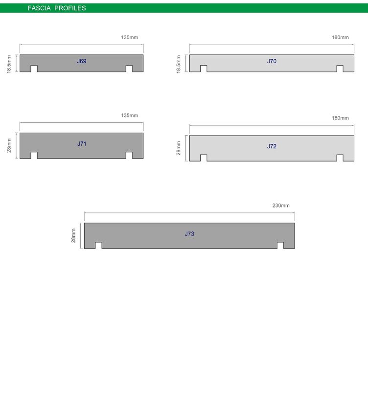
P age |4

Products and Accessories
WEATHERBOARDS
JSC RustiClad Weatherboards are available in different variety of species:
 SPECIES                                                            GRADES AVAILABLE
 Western Red Cedar (Thuja Plicata)                                  PC1, PC2, STK, Engineered
 Alaskan Yellow Cedar (Cupressus nootkatensis)                      PC1
 Radiata Pine – H3.2 (MicroPro® treated)                            Clears 1, Engineered
 Iroko (Milicia excelsa)                                            FAS
NOTE: Other species or grades may possible contact JSC Timber for more details

JSC Timber weatherboards are commonly available in 18.5 mm, 20 mm and 22 mm thickness and in a
variety of cover widths depending on the type of timber specie. The length spread in a random supply
varies between each specie and ranges from 0.9m to 6.1m, with selected lengths available on request.

JSC RustiClad weatherboards are machined to JSC profiles. Custom weatherboard profiles are also
available on request. Profiles can also be machined as paint profiles (radiused edges).

JSC Timber weatherboards come in Bandsawn Face (BSF) or Dressed Face (DF). A BSF finish
accentuates the natural texture of the timber and increases surface area for different coatings –
making for a longer lasting coating. A DF finish provides a smooth face that absorbs coatings well but
may need sanding. Check the sanding requirements from the coating manufacturers for dressed
boards.

NOTE: Machined samples, technical drawings, coated samples are available on request

NON-STRUCTURALLY FIXED – 20 MM CAVITY Batten
JSC-U Radiata Pine H3.2 treated timber universal cavity battens are castellated on both faces with an
18̊ degree slope to provide the drainage and ventilation.
    • 20 mm x 45 mm – for 20 mm cavity

NOTE: Only Universal Cavity Battens are available in MicroPro®

STRUCTURALLY FIXED – 45 MM CAVITY BATTEN
JSC-H Radiata Pine H3.2 treated timber universal cavity battens are castellated on both faces with an
18̊ degree slope to provide the drainage and ventilation.
    • 45 mm x 45 mm – JSC-V used vertically, and JSC-H used horizontally
    • 70 mm x 45 mm – JSC-V used vertically, and JSC-H used horizontally

TIMBER ACCESSORIES
Associated Mouldings
       Refer to Appendix – 1
Fascia Boards
       Refer to Appendix – 1

                        JSC RUSTICLAD WEATHERBOARD SYSTEM: SPECIFICATION AND INSTALLATON GUIDE v1.2 | June 2020
P age |5
FLASHINGS
As per NZBC E2/AS1 Section 4.0
• Flashing material should comply with E2/AS1 Table 20 and meet the compatibility of E2/AS1
Tables 21 and 22.
• Ensure that materials used for flashings are compatible with the window frame materials and
fixings and cladding materials and fixings. Windows to comply with NZS 4211 and all flashings
are to be in accordance with E2/AS1
• Refer to Figure 79 and Clause 9.4.4.5 E2/AS1 for internal and external corners
• Flashing materials for the flashings that are not easily replaceable should have an expected life
longer than cladding typically 25–50 years
NOTE : It is strongly recommended to use min 1.2mm thick aluminium flashing and install colour steel flashing
only at easily replaceable location. Provide adequate support for plastic flashings.
NAIL FIXINGS
Oil/Stain Finish
Use 316 Stainless Steel or Silicon Bronze annular grooved Rose Head, Pentagon Head or Flat head. The
length must allow 30 mm minimum embedment into the wall framing or the structural cavity batten.
Check material capability as per NZBC E2/AS1 Table 21 and 22.
Paint Finish
Use 316 Stainless Steel or Silicon Bronze annular grooved Jolt head, Countersunk and Rose Head. The
length must allow a minimum 30 mm embedment into the wall framing or the structural cavity batten.
Check material capability as per NZBC E2/AS1 Table 21 and 22.
NOTE: Refer to E2/AS1 Table 24 for the use of any alternative nail or screw of equivalent properties.
CAVITY CLOSER/VERMIN PROOFING
Use cavity closer/vermin proofing in compliance with E2/AS1 9.1.8.3 and Figure 66.
Install cavity closer/vermin-proofing at the base of all walls, open horizontal (or raking) junctions and
over openings (windows, meters etc). Length and width of cavity closer/vermin-proofing is to suit the
cavity.
Pre-Installation
DELIVERY, STORAGE & HANDLING
Correct handling and storage of JSC Timber weatherboard is critical for best performance, ease of use
and warranty adherence.
JSC Timber products should be delivered dry, unmarked and undamaged from freight and handling.
Don’t tip the weatherboards from a truck. All JSC Timber products should be lifted off the truck by
hoist or hand. All boards should be inspected upon the delivery.
NOTE: All the site deliveries should be with hoist or hand unload. Use of slings or chains could damage the
timber
Stack weatherboards horizontally, dry and clear off the ground by 100 mm and supported on dry,
clean timber bearers at maximum of 900 mm centres. Keep weatherboards dry at all times; either by
storing within an enclosed building or use an additional weatherproof cover as a secondary to JSC
packaging wrap if stored outside, but also ensure that there is sufficient air flow to avoid
condensation. Avoid storing over standing water or vegetation.
JSC RUSTICLAD WEATHERBOARD SYSTEM: SPECIFICATION AND INSTALLATON GUIDE v1.2 | June 2020P age |6
Delivery should be timed to allow minimum time sitting on site, especially when weatherboards are in
unfinished damp buildings or in an uncovered building allowing the chance of unwanted moisture
uptake. Extra care must be taken to avoid damage to weatherboards edges and surfaces, especially
during installation.
NOTE: Some coatings may require weatherboards to be separated or slip sheeted when in storage.
HEALTH & SAFETY
When handling JSC products or using tools, use appropriate PPE; included but not limited to eye, ear
and breathing protection for you and others who could be affected. Off cuts and sawdust of treated
and/or coated timber are to be disposed in accordance to local council requirements. Follow other
manufacturers advice on use, handling and disposal of other products such as coatings and adhesives.
PRE-COATING OF TIMBER COMPONENTS
The JSC Timber RustiClad Weatherboard System strongly recommend that the 1 st coat should be
applied before delivery. Boards must be coated all 4 sides prior to installation. Coating should be
selected and used according to manufacturer’s specifications.
Refer to www.jsctimber.co.nz/coatings for more information.
Installation
JSC RustiClad System must be installed by a suitably qualified and experienced trade person. Where
Restricted Building Work (RBW) applies the installer shall be a Licensed Building Practitioner (LBP) or
supervised by LBP.
PRIMARY STRUCTURE AND WALL UNDERLAY
Ensure that the substrate is straight and true. Wall underlay must be installed over the framing
directly i.e. under the cavity battens. The building wrap can be restrained from bulging into the
drained cavity by applying polypropylene tape at 300 mm centres. Trimmed openings are to be
prepared in accordance with NZBC E2/AS1 paragraph 9.1.5.
CAVITY CONSTRUCTION
Non-Structural Cavity Battens
JSC-U 45 mm x 20 mm battens are fixed temporarily with 50 mm stainless steel clouts over the wall
underlay and then firmly fixed by cladding fixings with a 30 mm minimum into the wall framing studs
as per NZBC E2/AS1 9.1.8.5.
Install JSC-U H3.2 treated castellated batten with 18°degree slope, sloping away from the wall
underlay towards the back of the weatherboard ensuring water is shed away from the framing.
Ensure cavity battens are spaced 10 mm from each other on ends/joins, internal and external corners
and when parallel.
For V/H and E/H wind zones (as defined NZS 3604: 2011) solid batten (non-castellated) required down
one significant side of external corner to provide pressure isolation between elevations.
Structural Cavity Battens
The JSC 45mm castellated batten is outside the scope of E2/AS1, which is limited to a nominal 20 mm
thick cavity battens. The 20 mm batten in E2/AS1 is a packer only, whereas the JSC – 45 mm x 45 mm
or 70 mm x 45 mm battens become a structural wall component.
JSC RUSTICLAD WEATHERBOARD SYSTEM: SPECIFICATION AND INSTALLATON GUIDE v1.2 | June 2020P age |7
The fastenings that secure the JSC-V 45 mm x 45 mm & 70 mm x 45 mm battens must have adequate
structural strength to support and transfer all applied loads back to the framing. All accessory
components including vermin proofing, cavity closures, back flashings and head flashings are custom
fabricated.
For vertical structural cavity battens for up to VH wind zones 1.8 kN and for EH wind zones 2.2 kN of
fixing tension is required per lineal meter of batten. For further information refer to
www.jsctimber.co.nz/structuralbattens .
MOISTURE MANAGEMENT
Moisture content of the framing must be less than 20% at the time of weatherboard fixing.
Immediately before installation, test the moisture content of the boards. Use a moisture meter to test
5% boards, but not less than 10 boards, in the centre of the length. Do not start fixing until 90% of the
values obtained are within the range in NZS 3602 Table 4 at time of installation. Ensure that at the
time of cladding installation the battens moisture content is no greater than 20%.
WEATHERBOARD INSTALLATION
Before weatherboards are installed make sure
• Necessary flashings are installed
• Cavity closure is installed continuously around the bottom of cavity
• Openings in cavity closer/vermin-proofing are kept clear and unobstructed in order to maintain
draining and venting of the cavity
• Back flashing is used behind the cladding at all corners to ensure weatherproofing of corners
• For windows and doors, head flashing stop ends are in place
• Weatherboards are dry and free of any contamination before installation.
• The back, face and edges are sealed with an appropriate exterior grade oil stain or alkyd primer.
It is recommended to apply one coat of an approved suitable exterior grade oil or stain prior to
installation. Any loose or bark encased knots or natural timber defects need be removed during
installation. All grades may require some docking.
Prior to start fixing weatherboard optimisation of board lengths is recommended to avoid unnecessary
wastage and joints. Check weatherboard length spread and use appropriately to suit each cladding
face.
Using laser or mechanical devices set-out all nailing accurately in straight lines. Align all weather
grooves. Ensure there is 25 mm lap for rusticated weatherboards with an expansion gap of 2 mm.
During installation, cut ends must be double sealed.
NOTE: The bottom boards of any wall should have an additional coat of primer to the exposed back of the board
to ensure water proofing and should then be top-coated wherever visually exposed – E.g. at the outside bottom
edge of the soffit.
JSC Timber RustiClad weatherboards must be pre-drilled with a slight (2°+) upward slope, 1 mm
smaller than the nail shank in order to reduce the risk of moisture entry. Single fix each weatherboard
at each fixing point in order to achieve a minimum of 30 mm fixing penetration into the framing.
NOTE: Scribers must be bedded in sealant to weatherboards for weatherproofing
JSC RUSTICLAD WEATHERBOARD SYSTEM: SPECIFICATION AND INSTALLATON GUIDE v1.2 | June 2020P age |8
Optional Clinch Nails
40 mm x 2.0 mm grade 316 stainless steel may be used to retain hidden lap tongues of weatherboard
profiles. Clinch nails are not a requirement of JSC or NZBC E2/AS1 and are an aide to installation only.
Finishing
COATING
Oiled/Stained finish – Finish the nail heads flush onto and not into the board surface. Do not 'over
drive' the nail head and crush the timber surface beneath and surrounding the nail. All cut ends
and/or uncoated surfaces shall be double coated during installation to protect against moisture.
Follow the stain manufacturer’s instructions at all times for application of stain finish.
Paint Finish – Remove all sharp edges to provide a radius to aid in uniform paint finish. Prime all cut
ends and bare timber surfaces twice by a premium alkyd primer. Nails are to be punched and the holes
to be primed without delay. Fill holes with suitable filler. Filled holes to be primed again and sanded
once dry. Ensure the surface is clean and free from any contaminants and apply two top coats allowing
time for drying between coats. Follow coating manufacturer’s instructions at all times for application
of the paint finish.
NOTE: Scribers sharp edges should be sanded to help paint film strength and primer at the ends should be
thoroughly brushed in to fully seal against moisture which may allow tannin through the primer and affect the
topcoats.
QUALITY CHECK
On completion, visually inspect all sides of the building ensuring the cladding system is completely
weathertight. The building owner should be advised of all maintenance requirements.
Maintenance
Building owners are responsible for the maintenance of their JSC weatherboards. Annual inspections
by a suitable person must be made to ensure that all aspects of the cladding remain in a weatherproof
condition. Repair to the damaged areas and where signs of deterioration are evident, must be
addressed immediately.
Regular cleaning of the surface with a soft brush, warm water and detergent is recommended to
maximize the life and appearance of the cladding. Any build up or organic material should be cleaned
away.
Recoating should be at intervals likely in accordance with coating manufacturer’s guidelines. More
exposed Northern and Western faces will require more frequent recoating.
See BRANZ Good Practice Guide Timber Cladding 3 rd edition for more information.
JSC RUSTICLAD WEATHERBOARD SYSTEM: SPECIFICATION AND INSTALLATON GUIDE v1.2 | June 2020P age |9
Appendix 1
PROFILE PORTFOLIOS
JSC RUSTICLAD WEATHERBOARD SYSTEM: SPECIFICATION AND INSTALLATON GUIDE v1.2 | June 2020P a g e | 10 JSC RUSTICLAD WEATHERBOARD SYSTEM: SPECIFICATION AND INSTALLATON GUIDE v1.2 | June 2020
P a g e | 11

*Profiles and grades may vary by species.
 Refer to individual species documentation for further information or contact us TechHelp@jsctimber.co.nz

                     JSC RUSTICLAD WEATHERBOARD SYSTEM: SPECIFICATION AND INSTALLATON GUIDE v1.2 | June 2020
P a g e | 12
RUSTICLAD COMPONENTS
Corner Flashing
• Minimum 30mm coverage past any butted joint
Flashing Type Minimum Flashing Size (in mm) per Wind Zones
Normal EH & VH
Hemmed Min. 50x50 75x75
Unhemmed 75x75 100x100
• Materials to comply with NZBC E2/As1 Paragraph 9.4.5.3
• For PVC or other flexible materials ensure flashing maintains contact with back of
cladding if required use extra cavity batten
Head Flashing
• Must be a minimum upstand of 35 mm, 75 mm in EH wind zone
• In accordance with NZBC E2/AS1 Paragraph 9.1.10.4 or window manufacturer’s
instructions
• Usually supplied by joinery companies
• Refer to JSC Window Technical details
Flat Back Flashing
• Recommended 100mm wide with minimum 30mm coverage from any butt
joint
• Materials to comply with NZBC E2 Table 20
• For PVC or other flexible materials ensure flashing maintains contact with
back of cladding if required use extra cavity batten
Z Flashing
• Must have a minimum upstand of 75mm, in EH wind zones use hemmed flashings
• In accordance with NZBC E2/AS1 Paragraph 4.6.1.7
• Refer to JSC Horizontal Joint technical detail
Cap Flashing
• Must be in accordance with NZBC E2/AS1 Paragraph 6.4
• Refer to JSC Parapet technical detail
Cavity Closer
• Size to suit cavity
• Materials to comply with NZBC E2/AS1 9.1.8.3; or
Covered by CodeMark or a BRANZ Appraisal
• Minimum vent 1000 mm² / linear meter
J Mould
Size to Suit
• 65mm X thickness of the weatherboard
• Materials to comply with NZBC E2 Table 20 or covered by CodeMark or a BRANZ
Appraisal
JSC RUSTICLAD WEATHERBOARD SYSTEM: SPECIFICATION AND INSTALLATON GUIDE v1.2 | June 2020P a g e | 13
Corner Soakers (External Corners)
• Materials - Stainless steel
Copper
Aluminium + Powder Coated
Galvanized + Painted on all sides
• Materials to be in accordance with NZBC E2/AS1 Paragraph 4.3.2 to 4.3.8
Flat Soakers (Scarf or Splay Joint)
• Materials - Stainless steel
Silicone Bronze
Aluminium
Galvanized
• Materials to be in accordance with NZNC E2/AS1 Paragraph 4.3.2 to 4.3.8
Weatherboard Fixings - Stain Finish
• Materials to comply with NZBC E2/AS1 Table 21 and 22
• Length per NZBC E2 Table minimum 30mm embedment
• Stainless steel or Silicone bronze Annular grooved Rose Head, Pentagon Head and
Flat Head
Weatherboard Fixings - Paint Finish
• Materials to comply with NZBC E2/AS1 Table 21 and 22
• Length per NZBC E2 Table minimum 30mm embedment
• Stainless steel or Silicone bronze Annular grooved Jolt Head, Countersunk and
Rose Head
Clouts
• Materials to comply with NZBC E2/AS1 Table 21 and 22
• Length per NZBC E2 Table minimum 30mm embedment
• Stainless steel or Silicone bronze Annular grooved Jolt Head, Countersunk and
Rose Head
Other Fixings
• Any other fixing shall comply with NZS 3604 or other relevant documents
Sealant
• To comply with NZBC E2/AS1 Section 9.5.3.2
• To be compatible with coating and other elements
JSC RUSTICLAD WEATHERBOARD SYSTEM: SPECIFICATION AND INSTALLATON GUIDE v1.2 | June 2020P a g e | 14
Wall Underlay
• To comply with NZBC E2/AS1 Table 23 or
• Wall underlays covered by CodeMark or a BRANZ Appraisal used within the scope
Rigid Air Barrier
• To comply with NZBC E2/AS1 Table 23 or
• Covered by CodeMark or a BRANZ Appraisal used within the scope
• Installed and handled per manufacturers specification
Flashing Tape
• To comply with NZBC E2/AS1 Section 4.3.11 or
Product with a CodeMark or a BRANZ Appraisal used within the scope
• To be compatible with wall underlay
Meter Box
• Recommended to be in a sheltered location
• Refer to JSC Meterbox Technical details
Pipe Penetration Boot
• To comply with NZBC E2/AS1 Paragraph 9.1.9.3; or
Covered by CodeMark or a BRANZ Appraisal used within the scope
• To be installed per manufacturers specifications
Window Joinery
• To be in installed accordance with NZBC E2/AS1 Sections 9.1.10 - 9.1.10.8 and
NZS 4211
Coating
• Should be suitable to use as external cladding coating
• All weatherboards are recommended to be delivered to site with one coat of
selected coating on all four sides
• Coat the cut ends with two coats wet on wet
• Subsequent coats are done after the installation
• Follow manufacturers specifications at all times
JSC RUSTICLAD WEATHERBOARD SYSTEM: SPECIFICATION AND INSTALLATON GUIDE v1.2 | June 2020P a g e | 15
Appendix 3
EXTERNAL REFERENCES
This document must be read in conjunction with
• MBIE [January 2017] Acceptable Solutions and Verification Methods for New Zealand Building Code (NZ
Building Code) Clause E2 External Moisture (refer to www.building.govt.nz).
• Department of Building and Housing (DBH) June 2006. Constructing Cavities for Wall Claddings (refer to
www.building.govt.nz).
• BRANZ Bulletin BU468 [December 2005] Fixing Timber Weatherboards (refer to www.branz.co.nz).
• BRANZ [May 2015] Good Practice Guide: Timber Cladding (refer to www.branz.co.nz).
• BRANZ Bulletin BU582 [April 2015] Structurally Fixed Cavity Battens (refer to www.branz.co.nz)
JSC RUSTICLAD WEATHERBOARD SYSTEM: SPECIFICATION AND INSTALLATON GUIDE v1.2 | June 2020You can also read