V3-Razr Repair Manual - Technical Support Group - April 2005
←
→
Page content transcription
If your browser does not render page correctly, please read the page content below
Technical Support Group

                              V3-Razr Repair Manual

      April 2005
      KS-042050-V1.2
      D54

Document –ED05020 rev.1.2
This document is considered an uncontrolled document when printed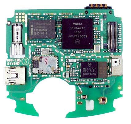
V3-Razr Repair Manual

                           TABLE OF CONTENTS
M
MOOD
   DUUL
      LEE 11                                                         2
TECHNOLOGY                                                           3
GSM OVERVIEW                                                         3
   PREFACE                                                           3
   SYSTEM ARCHITECTURE                                               3
PRODUCT FUNCTIONALITY                                                6
FEATURES                                                             6

M
MOOD
   DUUL
      LEE 22                                                         9
   PARTS LIST                                                       10
   MOL                                                              11
   REPAIR CATEGORIES                                                12
   LABOUR RATES                                                     13

M
MOOD
   DUUL
      LEE 33                                                        14
   ASSEMBLY & DISASSEMBLY                                           15
   KNOWN ISSUES & RESOLUTIONS                                       26
   SERVICE WEBSITE                                                  28
   REPAIR CODES                                                     29
   CLAIMABLE PARTS                                                  29

M
MOOD
   DUUL
      LEE 44                                                        30
   TEST EQUIPMENT                                                   31
   SOFTWARE                                                         32
   ACCESSORIES                                                      33

Document –ED05020 rev.1.2
This document is considered an uncontrolled document when printed
                                    Page 1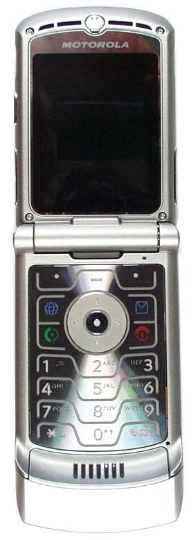
V3-Razr Repair Manual

                                               Module 1

                                     MODULE 1

                         • -Technology

                         • -Product functionality

                         • -Features

                                       Page 2
Document –ED05020 rev.1.2
This document is considered an uncontrolled document when printed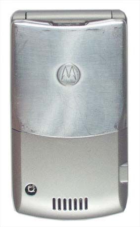
V3-Razr Repair Manual

                                           Technology
                                    GSM overview
Preface
This page discusses the GSM mobile telephony system, which is increasingly
popular and established throughout the world. The term GSM usually means
the GSM standard and protocols in the frequency spectrum around 900MHz.
There is also DCS1800 - GSM protocols but at different air frequencies around
1800 MHz - and in the United States, where spectrum for Personal
Communication Services (PCS) was auctioned at around 1900MHz, operators
using the aptly-named GSM1900 are competing against a plethora of other
standards. As a result of this, the original and most widely-used GSM
frequency implementation is also becoming known as GSM900, and DCS1800
is also known as GSM1800. However, although the physical frequencies used
differ, the protocols and architecture remain the same.

System architecture
Figure 4 below shows the GSM system architecture, which consists of the
switching system, the base station system and the user equipment.

Document –ED05020 rev.1.2
This document is considered an uncontrolled document when printed
                                    Page 3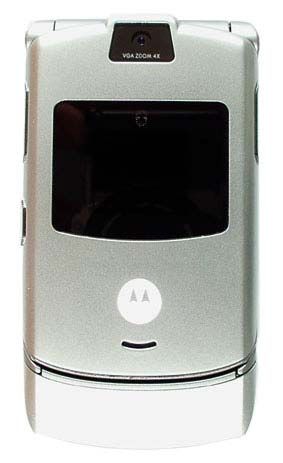
V3-Razr Repair Manual

               G SM , Basic Cellular System

                                            MSC
                                                                               P S TN

                                                  BSC

                        BTS
                        B TS

                                     B TS                   B TS

 Area divided up into Cells each with its own Base Transceiver station
 (BTS) which operates on its own set of frequencies
 The BTS are controlled by their own BSC (Base station controller) which
 can control multiple BTS
 The BSCis connected to the MSC (usually by land line) so the digital over
 air connection is from the Mobile to the BTS, the link from the BTS to the
 BSC can also be by land line.
 MSC : Mobile Switching Centre acts as the interface to the PSTN.

                        GSM , Basic Cellular System

                                 1                      1
                                            2                      3 Cell repeat pattern
                                 3                      3
                                             1
                                                                   Only
                                                                   O nly possible in GSM due to
                                2                       2          higher cross channel interference
                                                                   tolerances
                                             3

               3 cell repeat: possible in GSM due to higher tolerance to
               cross channel interference. digital timing specs etc.
               Other patterns apply,

                                            Page 4
Document –ED05020 rev.1.2
This document is considered an uncontrolled document when printed
V3-Razr Repair Manual

                                 Product Functionality

    • Form Factor: Clamshell
    • Finish:      Tri-coated paint, colour TBD
    • Bands/Modes: GSM : 850/900/1800/1900
                   GPRS Class 10
    • Size:        63 cc
    • Weight:      90g
    • Dimensions:  98 x 53 x 15
    • Display:     176 x 220 64K TFT internal
                   96 x 80 4K CSTN external
    • Antenna:     Internal
    • TT/SB Time:  TBD (700mAh Battery)
    • Audio        MIDI (24Ch/22Khz),
                   MP3 Ring tones

                                               Features

    •    Superior Design and CMF
    •    Internal Quad-Band Antenna
    •    External Picture caller ID
    •    Integrated VGA camera
    •    Integrated Class 1 Bluetooth™
    •    22kHz MIDI and polyphonic speaker
    •    MPEG4 video playback
    •    3D Graphics Engine
    •    UI Skinning
    •    SyncML
    •    Mini-USB connector

                                    Page 6
Document –ED05020 rev.1.2
This document is considered an uncontrolled document when printed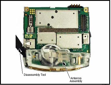
V3-Razr Repair Manual

                                       Physical Overview

                         MOTOROLA V3

                                                                    Speaker

     Camera Lens
                                                              64k TFT
                                                          176 x 220 Display
                                                                              VA/VR Key

                                                              4k CSTN
                                                             96 x 80 CLI

                                                                              5way Nav Key

                                                                                 Mic

                                       Page 7
Document –ED05020 rev.1.2
This document is considered an uncontrolled document when printed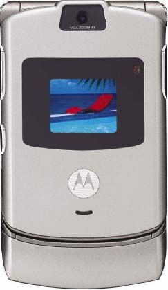
V3-Razr Repair Manual

                             Physical Overview (Cont’d)

                         MOTOROLA V3

        Volume up/down                                               Batt. Door

                 Soft key

                                                                    MIDI Speaker
                                                            Ext.
                                                          Antenna
                    USB

                                       Page 8
Document –ED05020 rev.1.2
This document is considered an uncontrolled document when printed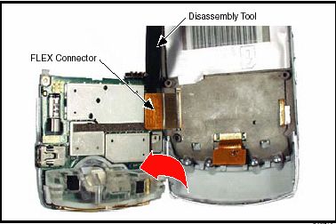
V3-Razr Repair Manual

                                MODULE
                                  Module 2 2

                    • -Piece Parts

                    • -Motorola on line(MOL)

                    • -Repair Categories

                    • -Labour Rates

                                       Page 9
Document –ED05020 rev.1.2
This document is considered an uncontrolled document when printed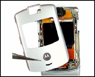
V3-Razr Repair Manual

                                          Parts List
                              Exploded View Diagram: V3

Part Description                 Part Number                             Part Description     Part Number

1-Lens                          6190016N03                               11-Front grill   p/o Front housing
2-Front Flip housing            1590025N02                               12-Antenna Cover p/o Front Housing
3-Display Module                7290086N01                               13-Antenna           1590051N03
4-Display Call ID               7287518Y01                               14-Back Housing      1590048N01
5-Flex Circuit                  8490007N01                               15-Midi Speaker      5088017N02
6-Flip Housing Back             0790000N01
7-Lens Caller ID                6190015N02
8-Keypad                        3888182Y03
9-Keyboard Assy.                8489976N02
10-Front Housing                1590043N01

                                            Page 10
     Document –ED05020 rev.1.2
     This document is considered an uncontrolled document when printed
V3-Razr Repair Manual
All piece parts and prices for the V3 model
are available when you log into the
Motorola on-line system (MOL)
Motorola On Line (MOL)
To Place your piece parts order please log in to:
http//businessonline.motorola.com
You will be asked to enter your Motorola on-line Logon ID and
Password.
Part numbers and prices are subject to change without notice.
Please reference the terms and conditions on the MOL website.
If you do not have login ID and password:
Please see signup information on MOL startup page.
You will need to provide the following Information:
(A) Your company name
(B) Your company ship to address
(C) Your company billing address
(D) Contact name
Page 11
Document –ED05020 rev.1.2
This document is considered an uncontrolled document when printedV3-Razr Repair Manual
Repair Categories
There are Seven (7) repair categories
(1) Major repairs – REP01- e.g. Major component
replacement.
(2) Minor Repairs – RMP01 or RPR01- Simple
component replacement – e.g. Non- soldered
parts.
(3) Basic Repairs – RSP01 or RAS01 - e.g. Re-
solder simple components, clean contacts.
(4) Batt repair – RBT01 – e.g test and or replace
battery
(5) Software – SWU01 – e.g Flashing, force
flashing
(6) Antenna - RAN01 – e.g test and or replace
antenna.
(7) Sent-mot - FWD01 - unknown or unauthorized
repairs sent to Motorola or authorized service
centre
The examples above are for reference only, each
repair category contains many more items than are
listed here. Motorola reserves the right to add,
remove or change items in each repair category
from time to time.
Page 12
Document –ED05020 rev.1.2
This document is considered an uncontrolled document when printedV3-Razr Repair Manual
Labour Rates
Please refer to your warranty compensation
schedule for warranty labour rates.
Motorola provides a limited warranty of twelve
(12) months on the V3 phone. Proof of purchase
must be provided in order to validate warranty.
In order to be paid for in-warranty repairs
performed in your service centre you must
submit a warranty claim through Motorola
Service link system.
NOTE:
Motorola will not reimburse the service centre
for repairs performed on V3 units unless your
technicians are trained on this specific model.
Page 13
Document –ED05020 rev.1.2
This document is considered an uncontrolled document when printedV3-Razr Repair Manual
MODULE
Module 3 3
• -Assembly & Disassembly
• -Architecture
• -Known issues & resolutions
• -Service Website
• -Repair Codes
• -Claimable Parts
Only technicians that are Motorola trained on the V3 model are
allowed perform in-warranty repairs on the V3 phones.
Page 14
Document –ED05020 rev.1.2
This document is considered an uncontrolled document when printedV3-Razr Repair Manual
Disassembly & Assembly –V3 Razor
This product contains static-sensitive devices. Use anti-static
handling procedures to prevent electrostatic discharge (ESD) and
component damage.
Removing and Replacing the Battery Housing and Battery
1. Ensure the phone is turned off.
2. Press in and hold the battery door latch as shown.
3. Rotate the battery cover upwards and lift it completely off the phone.
4. Lift the end of the battery first, and then remove it from the phone.
5. To replace, Align the battery with the battery compartment so the
contacts on the battery match the battery contacts in the phone.
6. Insert the battery, contacts side first, into the battery compartment and
push down followed by the opposite edge of the battery.
Page 15
Document –ED05020 rev.1.2
This document is considered an uncontrolled document when printedV3-Razr Repair Manual
7. Insert the bottom edge of the of the battery cover into the rear housing,
then push the top edge of the cover down and snap it into place.
Removing and Replacing the Subscriber Identity Module (SIM)
1. Remove the battery cover and battery as described in the procedures.
2. Slide the SIM card out of the phone as shown.
3. Carefully lift the SIM from the phones.
4. To replace, insert the SIM into the holder, ensuring the keyed corner of
the SIM faces the outside of the phone.
5. Replace the battery and battery door as described in the procedures.
Removing and Replacing the Rear Housing
1. Remove the battery cover, battery, and SIM as described in the
procedures.
2. Using a Torx driver with a T-5 bit, remove the screws at each side of
the phone. Retain the screws for reassembly..
Page 16
Document –ED05020 rev.1.2
This document is considered an uncontrolled document when printedV3-Razr Repair Manual
3. Release the four housing latches by inserting the pointed end of the
plastic disassembly tool into the openings on the rear housing.
4. Carefully rotate the rear housing away from the front housing and flip
assembly.
5. Use the disassembly tool to unseat the flex connector from it’s socket.
6. Lift the rear housing assembly away from the phone.
7. To replace, carefully align the flex connector to it’s socket on the rear
housing assembly, then gently press down on the flex connector until it is
properly seated in it’s socket.
8. Rotate the rear housing assembly so it sits over the phone.
9. Align the housing latches with the corresponding openings on the front
housing. Gently press the housings together until the catches snap into
place.
Page 17
Document –ED05020 rev.1.2
This document is considered an uncontrolled document when printedV3-Razr Repair Manual
10. Replace the 2 housing screws and tighten to a final torque setting of
1.5 inch pounds. Do not over tighten.
11. Replace the antenna, SIM, battery, and battery cover as described in
the procedures.
Removing and Replacing the Antenna
1. Remove the battery cover, battery, SIM, and rear housing assembly as
described in the procedures.
2. Use the metal tweezers to grasp the rubber antenna grommets and
carefully remove them from the antenna assembly. See Figure 7. Set the
rubber grommets aside for reuse.
Fig7
3. Use the disassembly tool to release the antenna assembly as shown in
Figure 8.
Page 18
Document –ED05020 rev.1.2
This document is considered an uncontrolled document when printedV3-Razr Repair Manual
4. Carefully lift the antenna assembly away from the phone.
5. To replace, align the antenna assembly to the phone.
6. Carefully press the antenna assembly into position until the antenna
assembly latches snap into position.
7. Reinstall the rubber antenna assembly grommets into their slots. Each
antenna grommet is uniquely shaped to fit into its respective position.
8. Replace the rear housing assembly, SIM, battery and battery cover as
described in the procedures.
Removing and Replacing the Transceiver Board Assembly
1. Remove the battery cover, battery, SIM, antenna, rear housing and
battery tray as described in the procedures.
2. Lift the transceiver board assembly out of the front housing with the
metal tweezers. See Figure 9.
Fig9
3. To replace, insert the transceiver board assembly into the rear housing.
4. Carefully and gently press the transceiver board into position and until
it snaps into place.
5. Replace the antenna assembly, rear housing, SIM, battery, and battery
cover as described in the procedures.
Page 19
Document –ED05020 rev.1.2
This document is considered an uncontrolled document when printedV3-Razr Repair Manual
Removing and Replacing the Flip Assembly Cover
1. Remove the battery cover, battery, SIM, antenna, rear housing, and
transceiver board assembly as described in the procedures.
2. Remove the 4 flip assembly screw caps.
3. Use the T-5 driver to remove the 4 screws from the flip assembly (see
Figure10). Retain the screws for re-assembly.
Fig10
4. Before removing the flip cover, note the locations of the smart buttons
on the sides of the flip assembly.
5. Use the disassembly tool to gently pry off the flip cover (see Figure 11).
Page 20
Document –ED05020 rev.1.2
This document is considered an uncontrolled document when printedV3-Razr Repair Manual
Fig 11
6. Remove the smart buttons on the side of the flip assembly. Set them
aside for reassembly.
7. Lift the flip cover away from the flip assembly. Be careful not to damage
the display flex cable (see Figure 12).
Fig 12
Page 21
Document –ED05020 rev.1.2
This document is considered an uncontrolled document when printedV3-Razr Repair Manual
8. To replace, insert the smart buttons into the phone. Ensure the buttons
contact their respective switches on the display assembly.
9. Align the flip cover to the flip assembly, gently press the flip cover onto
the flip assembly until the flip cover latches engage.
10. Insert and tighten the 4 screws to secure the flip cover to the flip
assembly. Avoid damage to the flex cable.
11. Insert the 4 rubber screw covers over the flip assembly screws.
12. Replace the transceiver board assembly, rear housing, antenna
assembly, SIM, battery, and battery cover as described in the procedures.
Removing and Replacing the Camera Assembly
1. Remove the battery cover, battery, SIM, antenna, rear housing, and
transceiver board assembly, flip assembly cover, and CLI lens cover as
described in the procedures.
2. Unlock the ZIF connector and remove the camera assembly flex
connector.
3. Carefully lift the camera assembly and flex out of the flip assembly (see
Figure 13).
Fig 13
4. To replace, carefully press the camera assembly into its slot in the flip
assembly.
5. Insert the end of the camera assembly flex cable into its slot in the ZIF
connector on the flip display assembly. Avoid damage to the flex cable.
6. Replace the flip assembly cover, transceiver board, rear housing,
antenna, SIM, battery, and battery cover as described in the procedures.
Page 22
Document –ED05020 rev.1.2
This document is considered an uncontrolled document when printedV3-Razr Repair Manual
Removing and Replacing the Display Module Assembly
1. Remove the battery cover, battery, SIM, rear housing, antenna,
transceiver board assembly, flip assembly cover, and camera assembly,
as described in the procedures.
2. Use the disassembly tool to unseat the display module assembly flex
connector from its socket (see Figure 14)
Fig 14
3. Carefully and gently lift one corner of the display module assembly out
of the flip assembly.
4. Avoid damage to the electrical components on the flex while carefully
removing the display module assembly from the flip assembly.
5. Carefully lift the display lens away from the flip assembly.
Page 23
Document –ED05020 rev.1.2
This document is considered an uncontrolled document when printedV3-Razr Repair Manual
Fig 15
6. To replace, align the display module assembly to the flip assembly.
7. Carefully lower the display module into the flip assembly. Ensure that
all of the display none of the display assembly components are damaged.
8. align the flip display flex to the flex connector on the flip display
assembly and gently press down on the flex connector until properly
seated.
9. Replace the camera assembly, flip assembly cover, transceiver board,
rear housing, antenna, SIM, battery, and battery connector as described
in the procedures.
Page 24
Document –ED05020 rev.1.2
This document is considered an uncontrolled document when printedV3-Razr Repair Manual
V3 Razr Block Diagram
Block Diagram
Cell DSP Peripherals DSP Memory VGA
Viterbi accelerator, L1 encryption, DSP XRAM 20K×16
timer, DSP Interrupts Cam
GSM YRAM 20K×16
XROM 24K×16
4 DSP YROM 24K×16
Quard Dual Digital
I,Q ONYXu PRAM 3.5K×24
Saw ÷n A2D Filters DMA
Display
4 104MHz PROM 104K×24
Filter 4
DCS 4
RX Control TX & RX Phase
32MB
Debug/Patch SRAM
TX Control
Charge Detector Shared (MCU) 32K×32 FLASH
PCS Pumps Memory or 4MB
6K×16 (DSP) 32K×24 RAM
Fractional
26MHz RF Divider
÷5 Synthesizer
RX VCO SIM
Eagle 3.6-3.9 GHz 722-915 MHz Prescaler
MCU MCU Memory CARD
÷5/6
ARM7 RAM 438K×8
52MHz ROM 3.1M×8
÷2 1 2 3
HB TX VCO
1710-1910 MHz 1710-1910 MHz 4 5 6
MCU Peripherals
Neptune L1 Timer, RTC, SPI,
7 8 9
Keypad Controler, GPRS * 0 #
Encryption, SIM Card,
TX General Audio Timers, Exterrnal memory
824-915 MHz LB TX VCO
Power Purpose Codec controler, Vectored
PAC 824-915 MHz
Control A2D Interrupts, W atch points
2 Algae MB
USB
(requires
Multiplex USB
transceiver)
Battery
Bluetooth
Monitor
PCAP 3
32KHz On/Off
Control Regulators Mic
LI Bias
Commodity Items
SINGLE
Supplied by Motorola SPS
CELL
Supplied by National Semiconductor
Bluetooth
Neptune LTS PCAP
UART
RESET_N SAP
1.8VDC
ROM: 144 KB
RAM: 20 KB
1.8VDC
95L14 2.775VDC
(w/BRCM2035)
26MHz
32KHz
BLUE_CLK_EN*
Page 25
Document –ED05020 rev.1.2
This document is considered an uncontrolled document when printedV3-Razr Repair Manual
Known Issues & Resolutions
V3-Razr Known Issues
The repairs listed in this section are the only repairs that are
allowed to be performed on the V3 phone in the field. The repair
code and the problem found code must be indicated on your service
link claim for each repair or the claim will be rejected.
Customer SVL Root Cause Resolution/ Repair Associated Repair
Complaint problem Service code Part # Category
found centre action
code
Keypad does MKP01 Gold pads on Replace Keypad RMP01 8489976N02 Minor
not function keypad flex assembly (02/22/05)
misaligned
with metal
dome
No Display DIM01 Loose 40 pin Reconnect Flex RAS01 8489976N02 Basic
display flex Quantity = 0 (02/22/05)
connector
Missing lines DIS02 Defective CLI Replace Display RMP01 7290086N01 Minor
on CLI Display Assembly (02/22/05)
Display
Missing lines DIM02 Defective main Replace Display RMP01 7290086N01 Minor
on main Display Assembly (02/22/05)
Display
Short FTR10 Incorrect SMS Upgrade SWU09 NA Software
message time stamp software to (03/30/05)
time stamp current version
incorrect
Always SIM01 Broken pin Replace SIM RMP02 3989888N01 Minor
Display on SIM Block / J-SIM (04/20/05)
Insert Sim connector connector
-Problem Use proper N/A Send to FWD01 NA Send-mot
not listed problem assigned
found
- codes.
repair centre
Unauthorize (not codes
d repair above)
All defective parts are subject to audit, if a claim is found with a part that is not
defective the entire claim will be rejected.
Page 26
Document –ED05020 rev.1.2
This document is considered an uncontrolled document when printedV3-Razr Repair Manual
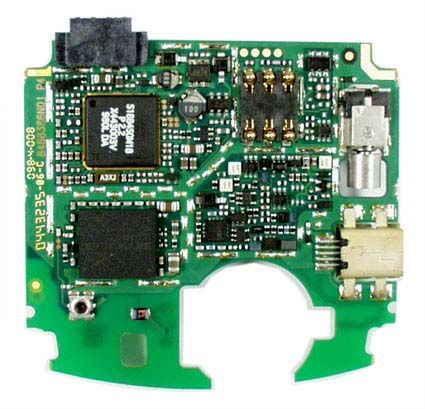
V3- Razr Board Layout
Top Side
J BATT
J SIM
U900 J VIB
PCAP3
Y900
32,768KHz
J USB
U50
Eagle
Bot Side
U700
U800
Flash/EEPROM/
Neptune
SRAM
J Keyboard
Y805
26MHz
J 41
MIC
FL100
SAW
U300
BT U150
Algae
Page 27
Document –ED05020 rev.1.2
This document is considered an uncontrolled document when printedV3-Razr Repair Manual
Service Website
Log on to the Motorola service website for more
repair information. You will also find schematic
diagram, block diagram, service bulletins,
advisories, software downloads and more for the
V3 phone.
The URL for the service website is:
https//pcs-service.motorola.com
Page 28
Document –ED05020 rev.1.2
This document is considered an uncontrolled document when printedV3-Razr Repair Manual
Repair Codes
Repair codes and problem found codes are to be
used for all repairs performed on V3 phones. The
repair code and the problem found code must be
entered on your service link claim or the claim will
be rejected. If multiple repairs are performed
simultaneously on a particular V3 unit then all
associated repair codes and problem found codes
must appear on the service link claim.
Claimable Parts
These are the only parts that you will be allowed to claim for
repairs on the V3 phone as of the publication of this manual.
Part Description Part #
Keyboard Assembly 8489976N01
Display Assembly 7290086N01
SIM Block / J-SIM Connector 3989888N01
Page 29
Document –ED05020 rev.1.2
This document is considered an uncontrolled document when printedV3-Razr Repair Manual
Module 4
MODULE 4
• -Test Equipment
• - Software
• -Accessories
Page 30
Document –ED05020 rev.1.2
This document is considered an uncontrolled document when printedV3-Razr Repair Manual
Tools and Test Equipment
Part Number Description Application
RSX4043 Torque Driver Used to remove and replace
screws
Purchase from Torque Driver Bit T-6 Used with torque driver
local supplier
SPN4716 Rapid Charger Used to charge battery and to
power Device
0180386A82 Antistatic Mat Kit Includes Provide protection from damage
6680387A95 mat to devices caused by
electrostatic discharge
4280385A59 Wrist Band Provide protection from damage
to devices caused by
electrostatic discharge
6680388B67 Disassembly plastic Tool Used during assembly/
disassembly
Purchase from Tweezers Plastic Used during assembly/
local supplier disassembly
Purchase from Tweezers stainless Used during assembly/
local supplier disassembly
Purchase from Wire cutters Used during assembly/
local supplier disassembly
Purchase from Digital Multi meter Used to measure voltage/current
local supplier
Page 31
Document –ED05020 rev.1.2
This document is considered an uncontrolled document when printedV3-Razr Repair Manual
Software
Current firmware version for the V3:
Software Version: R374_G_0E.40.7AR
Flex Version: GSMV3xxRGR01NA096
The Software Matrix is available to all ASC's and flash centres on our service
website at:
pcs-service.motorola.com
After logging in, go to "Software & Documents", then "Service Software &
Documents", then select "Documents" from the list.
Page 32
Document –ED05020 rev.1.2
This document is considered an uncontrolled document when printedV3-Razr Repair Manual
Accessories
Battery
Mid-Rate travel charger SPN4992
Desktop charger, mallard refresh SPN5029
Vehicle power adapter SYN7818
Speakerphone attachment SPN5028
Headset, FM stereo radio SYN8609
Headset, dual, retractable SYN8284
Headset, single, retractable SYN9050
Headset, send / end button SYN9351
Headset, over the ear SYN8908
Headset, silver AAYN4264
Hands-free (compatible with T-coil hearing aids) SYN7875
Data kit, USB S8951
Data kit, serial multi-connect S8952
Data kit, serial multi-connect for Palm™ III/V S8953
Data cable, USB SKN6311
Data cable, serial SKN6315
Data cable, serial for Palm™ III SKN6320
Data head, serial SYN0279
Page 33
Document –ED05020 rev.1.2
This document is considered an uncontrolled document when printedYou can also read