State of Charge (SOC) Governed Fast Charging Method for Lithium Based Batteries
←
→
Page content transcription
If your browser does not render page correctly, please read the page content below
State of Charge (SOC) Governed Fast Charging Method for Lithium
Based Batteries*
Fahmida Naznin
TVS Motor Company Ltd.
Post Box No. 4, Harita, Hosur, TN-635109, India; Email: fahmida.naznin@tvsmotor.co.in

* Patent pending

Abstract: The State of Charge (SOC) governed               CC-CV charging is the most widely accepted
fast charging method for secondary lithium             and universally used charging profile for lithium
based batteries proposed herein charges a battery      chemistries as it not only provides safest
many times faster than the normal Constant             charging but also most optimum battery
Current-Constant Voltage (CC-CV) charging and          performance and maximum battery life. It takes
reduces the side-effects generally accompanied         ~ 1.5-2 hours to completely charge a battery in
by various fast charging methods. The proposed         CC-CV mode and when we see EVs and HEVs
charging algorithm takes into account the              as our soon to be modes of transportation and
varying internal impedance of the battery at           when there is a constant comparison between the
different SOC levels and minimizes voltage             time it takes to fill a gasoline tank of a vehicle to
fluctuations. The charging method has been             the time required for charging a battery, the
demonstrated using a simulated lab test on a           feeling is far from comforting. Hence, there is a
3.72V lithium-ion battery cell from Navitasys,         lot of initiative for the development of fast
LLC and modeled using the Battery & Fuel cells         charging methods and infrastructures worldwide.
module along with the Events interface of              As a result, large numbers of fast charging
COMSOL Multiphysics 4.3b. The experimental             methods [1-5] have been devised in the past
and modeling results were compared with other          decade; but most of them negatively impacts the
state-of-the art fast charging methods available       battery performance in the long run and reduces
in the literature.                                     its cycle-life due to pumping of very high
                                                       currents into the battery within very short time
Keywords: Fast charging, lithium batteries,            durations. This leads to irreversible capacity loss
State of Charge, COMSOL Multiphysics                   as a result of dendrite formation which further
                                                       results in internal short-circuits and hence
1. Introduction                                        permanent       battery     failure.    Yury      M.
                                                       Podrazhansky et.al [6] discloses a method and an
     Considering the world’s current energy            apparatus to carry out rapid charging of lithium
starved scenario and the requirement to                based batteries while eliminating performance
persistently met the stringent emissions norms,        degradation as a result of formation of resistive
electric vehicles (EVs) and hybrid-electric            layers on electrode surfaces, dendritic formation
vehicles (HEVs) will soon become our most              and electrolyte decomposition.
common modes of transportation. The numbers
of EVs and HEVs sold worldwide are projected               In the same line of work, a novel fast-
to increase by 3 times in the year 2020. Almost        charging method (Figure 1) is presented in this
100% of the EV and PHEVs and 50-60% of the             paper for secondary lithium based batteries that
HEVs will be powered by lithium batteries as           is suitable for charging any lithium-ion, lithium-
amongst the available battery technologies,            polymer and solid-state lithium chemistry. The
lithium batteries have better automotive               charging profile has been carefully constructed
advantages which include higher gravimetric            by taking close consideration of the physical
energy density, higher cyclability, charge             processes involved in the battery during charging
efficiency without memory effect, etc. However,        and the varying impedance of the battery at
its cost, safety issues and long charging durations    different SOC levels so as to obtain optimum
are the major concerns.                                battery performance while charging it rapidly
                                                       and at the same time to avoid internal stress
                                                       within the battery active material and at the

          Excerpt from the Proceedings of the 2013 COMSOL Conference in Bangalore
electrode | electrolyte interfaces so as to obtain         thereby smoothening the concentration gradient
maximum cycle life.                                        on the anode surface. This step helps in
                                                           eliminating the chances of lithium plating on
2. The proposed fast charging method                       anode surface.

     Charging and discharging process in lithium       a
based batteries primarily involves the shuttling
of lithium-ions between the electrodes and
lithium-ion intercalation in the interstices of the
cathode and anode respectively. Since the time-
constant for solid-state diffusion within the
electrodes is much higher than the time constant
for diffusion in liquids, it is critical to provide
enough settling time for the lithium-ions to move
into the vacant sites of the host electrodes.          b
Otherwise, unmindful fast charging may result in
dendrite formation or lithium plating as a result
of accumulation of lithium-ions on the anode
surface and apart from capacity loss and cycle-
life degradation, it can pose serious safety threats
in the form of short-circuit, overheating leading
to cell bulging and also explosion in extreme
cases.

    It is advisable to start the charging process
from a lower current rate if the state of the
battery is unknown. Also, the battery encounters
high internal impedance at lower SOC levels            c
which may be the result of deep-discharge.
Impedance is also contributed as a result of
prolonged storage duration and storage at lower
temperatures. To account for higher impedance
at lower SOC levels, the first charging stage, C1
consists of a multistage Constant Current region
(m-CCi) where gradually increasing current
pulses of amplitude varying from 0.5C – 2C are
applied to the battery based on its SOC with                   Figure 1. The proposed fast charging method
alternate rest periods. This stage extends from 0          showing the (a) SOC (b) Current and (c) Voltage
= SOC < 50.                                                profiles

     The second charging stage, C2 (50 ≤ SOC <                 The third charging stage, C3 consists of
80) consists of a multistage Constant Current –            another multistage Constant Current region (m-
Constant Voltage (m-(CC-CV)) region. High                  CCr) where gradually decreasing current pulses
current pulses of amplitude in the range of 2C -           of amplitude varying from 0.5C – 2C are applied
8C are applied to the battery in the CC step as            to the battery based on its SOC with alternate
lithium batteries exhibits higher charge                   rest periods in order to account for the lower
acceptance and a flat discharge plateau in this            charge acceptance by the battery at higher SOC
region. A CV step is applied after each high               levels (80 ≤ SOC < 95).
charging current pulse, which reduces the
voltage fluctuations by restricting the battery                The final charging stage, C4 consists of a
voltage from dropping drastically after the CC             single CV step which is applied to the battery at
step. The CV step allows more time for the Li+             Vmax (charge cut-off voltage) after it has attained
ions to diffuse into the interstices of the anode          ≥ 95% SOC. The gradually decreasing current in

          Excerpt from the Proceedings of the 2013 COMSOL Conference in Bangalore
this stage slowly brings the battery to               where, Jn is the pore wall flux, η is the over-
equilibrium at the end of the charge. Charging is     potential due to electrode reaction, i0 is the
terminated once the charging current drops to         exchange current density and αa and αc are the
about 0.1C - 0.05C                                    symmetry factor for the negative and the positive
                                                      electrodes respectively.
    The charging profile may or may not follow
the stages in the exact order as proposed herein          Charge balance in the electrolyte is governed
depending upon the SOC level of the battery           by the liquid phase Ohm’s law given by:
prior to charging.
                                                                                2       ,
                                                          = −     ,   ∇∅ +                      1+      1
3. Use of COMSOL Multiphysics
                                                                           −        ∇
    A lithium-ion cell of lithium-manganese
oxide, LiMn2O4 chemistry has been modeled             where, σl,eff is the effective conductivity of the
using the Batteries & Fuel cells module and the       ions present in the electrolyte and ϕl is the liquid
proposed charging profile has been simulated          phase potential.
using the Events interface of COMSOL
Multiphysics 4.3b.                                      Charge balance inside the electrodes is
                                                      modeled using the solid phase Ohm’s law:
    The 1D lithium-ion battery model consists of
the following five domains (Figure 2):                                    = −       ,       ∅

 - Negative current collector (Copper) of length      where, σs,eff is the effective conductivity of the
   L_neg_cc                                           ions in the solid phase and ϕs is the solid phase
 - Negative electrode (LiXC6) of length L_neg         potential.
 - Separator of length L_sep with electrolyte
   (1:1 EC:DEC in LiPF6 salt)                            Diffusion or mass-transfer in the electrolyte
 - Positive electrode (LixMn2O4) of length            has been modeled using the Fick’s second law,
   L_pos                                              given by:
 - Positive current collector (Aluminum) of
   length L_pos_cc
                                                                 =          ,               + 1−

                                                      where, cl is the salt concentration in the solution
                                                      phase, Dl,eff is the effective diffusion co-efficient,
Figure 2. 1D model of the lithium-ion battery where
                                                      as is the surface area of the electrode per unit
A is x=0, B is x=L_neg_cc, C is x=L_neg_cc+L_neg,     volume and t0+ is the transference no. of Li+ ions.
D is x=L_neg_cc+L_neg+L_sep, E is x=
L_neg_cc+L_neg+L_sep+L_pos and F is x=                    The active materials of the electrodes are
L_neg_cc+L_neg+L_sep+L_pos+L_pos_cc                   assumed to be spherical particles of known
                                                      radius rp and the mass transfer within the
    The physical and electrical properties of all     electrodes is governed by the Fick’s second law
the domain materials have been derived from the       in spherical co-ordinates.
Material Library of COMSOL Multiphysics.
                                                                                            2
    The electrode reactions have been modeled                         =                 +
using the Butler-Volmer kinetic equation which
                                                      .
is given by the expression:
                                                      where, cs is the salt concentration in the solid
                                                      phase and Ds is the diffusion co-efficient of Li+
                                   −
        =     exp          −                          in the solid phase.

            Excerpt from the Proceedings of the 2013 COMSOL Conference in Bangalore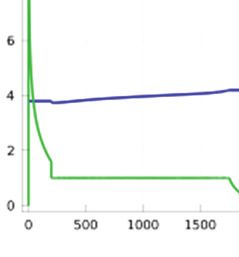
At the surface of the particles, flux is equal to                 using a series of implicit events in the Events
the rate of accumulation or generation of Li+ due                     interface present under the Mathematics node in
to the electrochemical reaction. It is given by:                      the Physics tree . An explicit event occurs at
                                                                      predetermined times and can be repeatedly
                                                                      invoked until the desired condition is fulfilled.
                                        =                             On the other hand, an implicit event occurs when
                                                                      a condition involving an indicator state is
   At the center of the particle, there is no flux.                   fulfilled. The switching of the charging profile
                                                                      from one stage to another is governed by the
                                                                      SOC of the battery which is given by:
                                        =0

                                                                                             =
    Also, there is no mass-flux at the electrode |                                                ,
current-collector interfaces. At the negative
electrode| negative current-collector interface:                      where, L is the length of the respective electrode.

                           ,                                             Further, the applied current is defined using a
                                                    =0                global ODEs and DAEs interface.
                                    _       _

    At the positive electrode| positive current-                      4. Results and discussion
collector interface:
                                                                          The lithium-ion cell modeled herein has a
          ,
                                                                      rated capacity of 10Ah, charge termination
                                                                 =0   voltage, Vmax of 4.2V, corresponding to 100%
                   _       _        _           _        _
                                                                      SOC and a discharge cut-off voltage of 3V,
                                                                      corresponding to 0% SOC.
where, cs,p and cs,n are the Li+ concentrations in
the negative and the positive electrodes
                                                                          The proposed charging profile simulated
respectively.
                                                                      using COMSOL (Figure 3) consists of 3
                                                                      charging levels in the C1 stage (m-CCi). In the
   The negative electrode is grounded at x=0;
                                                                      first level of charging from 0.2 = SOC < 0.3, a
                                                                      constant current of 0.7C (i.e., 7A) is applied to
                               ∅|       =0
                                                                      the battery whereas in the second level of
                                                                      charging from 0.3 ≤ SOC < 0.4, constant current
   A predefined charging profile, i_app is
                                                                      of 1C (i.e., 10A) and in the third level of
applied to the positive electrode;
                                                                      charging from 0.4 ≤ SOC < 0.5, constant current
                                                                      of 1.3C (i.e., 13A) is applied to the battery. In all
     ∅|        _       _       _        _           _        _    _   the levels, current pulse is applied for a period of
                                    =−_                               3s with alternate rest periods of 6s. In the C2
                                                                      charging stage (m-(CC-CV)); six CC-CV steps
    Double layer capacitance developed at the                         are performed till the battery SOC reaches 80%.
electrode | electrolyte interfaces as a result of                     Constant current pulses of 2C (i.e., 20A) is
accumulation of ions on the electrode surface is                      applied in the CC stage followed by a CV step.
modeled using the expression:                                         C3 charging stage (m-CCr) is carried out in 3
                                                                      charging levels. In the first level of charging
                               ∅            ∅                         from 0.80 = SOC < 0.85, constant current of
                       =            −
                                                                      1.5C (i.e., 15A) is applied to the battery whereas
                                                                      in the second level of charging from 0.85 ≤ SOC
where, adl is the double layer area.                                  < 0.9, constant current of 1C (i.e., 10A) and in
                                                                      the third level of charging from 0.9 ≤ SOC <
   C1 and C3 stages of the charging profile has                       0.95, constant current of 0.8C (i.e., 8A) is
been generated using a series of explicit events                      applied to the battery for a period of 6s with
whereas C2 and C4 stages has been generated

              Excerpt from the Proceedings of the 2013 COMSOL Conference in Bangalore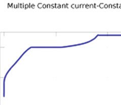
alternaate rest period
                     ds of 3s. Finaally, in the C4            a
chargiing stage, constant voltagee charging iss
perforrmed at 4.2V (V( max) to attaiin 100% SOC.
The tootal charging time taken to reach
                                   r      from 0%
                                                %
SOC tot 100% SOC using
                     u     this meth
                                   hod is 2500s (~
                                                 ~
42 min nutes).

                                                          b

Figuree 3. The proposed fast ch         harging method
                                                     d
simulatted using COMS   SOL Multiphysiics 4.3b showing
                                                     g
the celll voltage and chaarging current prrofiles

   Thhe proposed charging
                   c          meth
                                 hod has been   n
compaared with th he convention  nal Constant--
Currennt Constant-V
                  Voltage (CC-C CV) charging,,
multisstage Constan
                  nt-Current Constant-Voltagee
m-(CCC-CV) chargingg [1] and boostt charging [5].

    In CC-CV charg  ging (Figure 4a),
                                  4 a constantt
curren
     nt of 0.5C (5AA) is applied to
                                  o the battery in n              c
the Coonstant Curren
                   nt (CC) step tilll it reaches thee
chargee termination voltage, Vmax (4.2V). Next,,
Constaant Voltage (C
                   CV) charging iss performed at
Vmax till
      t the chargiing current drrops to 0.01C      C
(0.1A)). The charging
                    g time taken in
                                  n this method iss
8000s (~ 2.2 hrs).

    Thhe multistage Constant-Currrent Constant--
Voltag ge m-(CC-CV)) charging proffile (Figure 4b))
consissts of two CC-CV stages, i.e., CC-CV-CC--
CV. Charging
      C          is inittiated with a co
                                       onstant currentt
of 2C (20A) until th  he battery voltaage reaches itss
first sttage terminatioon voltage, V1 corresponding  g
to 80%  % SOC (4V)). Next, a con       nstant voltagee
profilee is applied ata V1 (4V) tilll the charging   g
currennt drops down to  t 0.7C (7A). The
                                       T second CC  C
stage follows at a constant
                       c          charg
                                      ging current off    Figurre 4. (a) Consstant Current- C     Constant Voltagge
0.7C till the baattery attains the chargee                (CC-C CV) charging profile, (b) M      Multiple Constaant
terminnation voltage, Vmax. Finally, a CV step iss        Curreent- Constant Vooltage (CC-CV-CC-CV) charginng
applied at Vmax till thhe charging currrent drops to      profille, (c) Boost chaarging profile (CV-CC-CV)

           Excerpt from
                   f    the Procceedings of th
                                             he 2013 COM
                                                       MSOL Conferrence in Banggalore
the prredetermined charge completion level off
0.01C (0.1A). The ch
harging time taaken using thiss
metho
od is 5400s (1.5
5 hrs).
A boost chargiing profile (F Figure 4c) iss
simulaated where a boost-charging g period of 5
minutees is applied to o the battery. It
I is a constantt
voltagge step where a high voltagee is applied to o
the baattery as a ressult of which a high currentt
inrushh is witnessed in this step du ue to very high h
potenttial difference. Next, the charrging profile iss
switch hed to normal CC-CV
C mode to
t attain rest off
the cap pacity. In this step,
s a constan
nt current of 1C
C
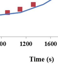
Figurre 5. Experimenntal charging proofile performed oon
(10A) is applied to the t battery till it attains Vmaxx
a 10A
Ah LiMn2O4 celll
follow
wed by a constaant voltage pro ofile at Vmax to
o
attain 100% SOC. The T total charg ging time taken n Thhe experimenttal and simulaation results fofor
in thiss method is 500 00s (~ 1.3 hrs).
the ccharging profilee shows very ggood correlatioon
with each other (Figgure 6).
Fo
or each charg ging profile, simulation
s hass
been run
r for 500 cy ycles to evaluatte the capacity
y
fade at
a the end of o cycling. Th he results aree
presen
nted in Table 1:
Tablee 1: Charging tim
me and capacity fade results of
the variou
us charging meth
hods
Cell
C capacity
Chaarging Charging
C
after 500
meethod time
t (s)
cycles (Ah)
CC
C-CV 8000 9.06
m(CC-CV) 5400 8.63
Boost 5000 8.42 Figurre 6. Experimenntal vs. Simulaation result of thhe
SOC based charging profile. Solid liine corresponds to
Proposed
2500 8.96 simullation data and dotted line represennts
SOCC based experrimental data
7. C onclusions
Thee results men ntioned in Taable 1 clearly y
indicaates the superiior perfrmancee of the SOC C
Thhe conventionnal CC-CV chharging providees
based charging metthod as the caapacity fade iss
the m most optimal charging perrformance with
minimmal and chargiing time is grreatly reduced d
minim mum battery ddegradation buut at the cost oof
compaared to other fast charging methods. CC--
largee charging timme. The variouus fast charginng
CV ch harging shows very little cap pacity fade butt
methhods available in the literatture are able to
at the cost of very larrge charging tiime.
reducce the chargingg time but are aaccompanied bby
largee capacity fade as well as safeety issues due to
Thee proposed SOOC based chargging profile hass
overhheating as a reesult of chargiing at very higgh
also been
b simulated
d in the lab (F
Figure 5) usingg
curreents. The SO OC based chharging methood
the Bitrode
B cell tester.
t A 10A Ah (1C rate))
propoosed in this work not onnly reduces thhe
LiMn2O4 prismatic battery cell frrom Navitasys,,
chargging time drrastically but also providees
LLC with
w a nominaal voltage of 3.72V has been n
optimmum battery peerformance annd better therm mal
used for
f experimentss.
manaagement due to controlled charging. Thhis
methhod has been evaluated both bby
Excerpt from
f the Procceedings of th
he 2013 COM
MSOL Conferrence in Banggalore
experimentation and simulation using COMSOL
Multiphysics 4.3b.

8. References

1. Anil Paryani et.al, Fast charging of battery
using       adjustable       voltage      control,
US2011/0012563 A1, 2011
2. Notten et.al, Method and charger for boost
charging a rechargeable battery on the basis of a
physical model, US2010/0148731 A1, 2010
3. Tomohisa Hagino, Pulse charging method for
rechargeable batteries, US5808447, 1998
4. Kenkichi Shimomoto, Battery charging
method and apparatus using initial charging step
with gradually increasing charging current, quick
charging step with large charging current and
final charging step with decreasing charging
current, US5500584, 1996
5. P.H.L. Notten, J.H.G Op het Veld, J. R. G.
van Beek, Boostcharging Li-ion batteries: A
challenging new charging concept, Journal of
Power Sources, 145, 89-94 (2005)
6. Yury M. Podrazhansky et al, Battery charger
for lithium based batteries, US6366056 B1, 2002
7. Long Cai, Ralph E. White, Mathematical
modeling of a lithium ion battery with thermal
effects in COMSOL Inc. Multiphysics (MP)
software, Journal of Power Sources, 196, 5985-
5989 (2011)

          Excerpt from the Proceedings of the 2013 COMSOL Conference in Bangalore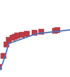
You can also read