Smart Thermostat Wireless - RDS110.R - Siemens
←
→
Page content transcription
If your browser does not render page correctly, please read the page content below
Smart Thermostat Wireless
RDS110.R

                     To control heating applications in apartments, single family homes, dormitories,
                     and other residential as well as commercial spaces.
                     ● Backlit, 90 mm color LCD touch screen for intuitive local operation
                     ● Mobile app for smart phones
                     ● Patented1) self-learning algorithm with PID response
                     ● Green leaf for energy-optimized operation
                     ● Operates automatically following a schedule
                     ● Presence detection via geo-fencing
                     ● Multifunctional inputs for remote sensors
                     ● Communicates with in-house devices via Thread
                     ● Integration into any BACnet system
                     ● Satisfies Class IV according to the Eco design directive
                     1) Patent pending

A6V11562461_en--_b                                                                                  Siemens AG
2021-07-16                                                                                   Smart Infrastructure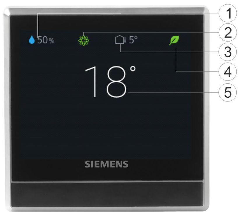
Room thermostat features
                ● Direct temperature and operating mode selection
                ● RoomOptiControl1) function with Green leaf indication for energy-optimized operation
                ● Temperature setting limitation for use in public spaces
                       ●   Air quality indication: “Good”    , “Okay”    , “Poor”
                       ●   Screen lock protection against unauthorized access
                       ●   Manual switchover between “At home”, “Away” and “Off” on touch screen
                       ●   Room temperature detection and control using the built-in temperature sensor or an op-
                           tional remote sensor
                       ●   Optional temperature averaging using an additional remote temperature sensor
                       ●   Patented self-learning algorithm with PID response (patent pending) guaranteeing opti-
                           mum temperature control performance in all room types
                       ●   Optimum start control function that advances the switch-on time to ensure the selected
                           setpoint is reached as required
                       ●   Floor temperature limitation using a remote, wired sensor in electric floor-heating appli-
                           cations
                       ●   Humidity control using the built-in humidity sensor or an optional remote sensor
                       ●   Two multifunctional inputs, optional and configurable for remote sensors (see section
                           Use [▶ 3] for more information)
                       ●   Periodic pump/valve operation to protect against seizing
                       ●   Navigation wizard for guided, fast commissioning
                       ●   Wireless communication with receiver RCR114.1 and radiator valve SSA911.01TH
                           through Thread
                       ●   Local modification of BACnet settings (see the User Guide [A6V11562455] for more in-
                           formation)
                       ●   Remote firmware upgrade capability

                       1) Automatically detect unnecessary energy consumption in the room and display it using
                       Green Leaf on the thermostat. When the leaf is red, the thermostat setting has been
                       changed. Touch the red leaf to return the setting to energy-optimized operation. See the
                       User Guide (A6V11562455) for more information on this function.

Remote operation and monitoring
                ● Mobile app for smartphones based on iOS and Android operating systems
                ● Support “Dark” and “Light” background colors on mobile app
                ● Manual switchover between “At home”, “Away” and “Off” operating modes on the mobile
                   app
                ● Presence detection using geo-fencing for energy-efficient operation
                ● Individual schedule for each day of the week can be programmed using the mobile app
                   with the following operating modes (maximum 8 modes per day)
                            – “Comfort”: To enjoy comfort and coziness when you are at home.
                            – “Economy”: To save energy when maximum comfort is not required, for example, in
                              the evening or at night.
                             – “Unoccupied”: To save energy costs by reducing the temperature setpoint, for exam-
                               ple, when the room is unoccupied.
                       ●   Individual schedule for domestic hot water boiler
                       ●   User account management
                       ●   Monitoring of actual and historical temperature and humidity values
                       ●   Secure access and data transmission with the Siemens Cloud Computing Platform

2
Siemens                                                                                             A6V11562461_en--_b
Smart Infrastructure                                                                                         2021-07-16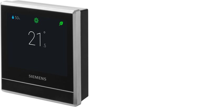
Use
                       The RDS110.R is designed to control heating applications in apartments, single family
                       homes, dormitories, and other residential and commercial spaces.
                       The RDS110.R controls the following plant components with its peripherals:

                       RDS110.R with radiator valve actuator (SSA911.01TH):
                       ● Radiator with valve (SSA911.01TH)
                       NOTE: The RDS110.R can control a maximum of 6 valve actuators in parallel, with the same
                       control settings.

                       RDS110.R with wireless receiver (RCR114.1):
                       ● Gas boiler
                       ● Radiator with pump
                       ● Electric floor heating
                       ● Fan with electric heating
                       ● Floor heating with valve
                       ● Floor heating with pump
                       ● Electric radiator
                       ● Electric boiler
                       ● Generic heating device

                             NOTICE

                       When selecting the gas boiler application, ensure a hydronic heating is used. The
                       RDS110.R is not calibrated for use in combination with a gas-fired ducted heating system.

                       The RDS110.R can control a maximum of 6 receivers in parallel, with the same control set-
                       tings.
                       The RCR114.1 has two relay outputs, one of which is for heating equipment (listed above).
                       The other relay is available to optionally control a domestic hot water (DHW) boiler, humidifi-
                       er or dehumidifier.
                       The RDS110.R has two multifunctional inputs, optional and configurable for:
                       ● Operating mode switchover contact
                            – The thermostat switches to the “OFF” mode if the input has been configured as Nor-
                              mally Open. Useful for a room or key card.
                       ●   Remote room temperature sensor
                            – The remote temperature sensor can acquire the current room temperature. If the
                               sensor input signal is lost, the thermostat controls the room according to the internal
                               sensor.
                       ●   Floor temperature sensor
                            – The floor heating limitation function prevents the floor temperature from exceeding a
                              preset value.
                       ●   Outside air temperature sensor
                            – The outside air temperature sensor can acquire outside air temperature information
                              for display on the touch screen.
                       ●   Remote humidity sensor
                            – The thermostat can control a standalone humidifier or dehumidifier. The relative hu-
                               midity is measured by the remote humidity sensor or internal humidity sensor.
                       ●   VOC and CO2 sensors
                       ●   Condensation monitor
                       ●   Universal contact. A notification shows up in the mobile application when the input status
                           switches to “Normally closed” (the circuit is closed).

                                                                                                                         3
Siemens                                                                                              A6V11562461_en--_b
Smart Infrastructure                                                                                         2021-07-16
●   Presence detector. The thermostat switches from “Unoccupied” to “Comfort” if the detec-
                           tor detects someone in the room. It remains in “Unoccupied” for a maximum of one hour
                           after the last presence detection.

                             NOTICE

                       See the User guide (doc ID: A6V11562455) for more information about input configurations.

Topology

                       NOTES:
                       1. Install the receiver close to the RDS110.R if possible. The communication range in a
                          building is typically 60 m, without any blockages. Note that range can vary, because
                          walls, floors, wireless interference and other factors may reduce the signal strength.
                       2. Add a repeater (RCR114.1) if the connection fails due to low signal strength (distance or
                          blockagers [walls, and so on]).
                       3. The thermostat can only connect to one heating system. It cannot simultaneously control
                          the wireless relay and the valve actuator.
                       4. The thermostat can control up to six wireless relays or valve actuators.

Mechanical design
                The room thermostat consists of the following parts:
                ● Housing front with touch screen
                ● Housing rear with terminals and temperature sensor
                ● Metallic mounting plate for wall mounting
                ● Accessories

4
Siemens                                                                                              A6V11562461_en--_b
Smart Infrastructure                                                                                         2021-07-16
Operation and settings
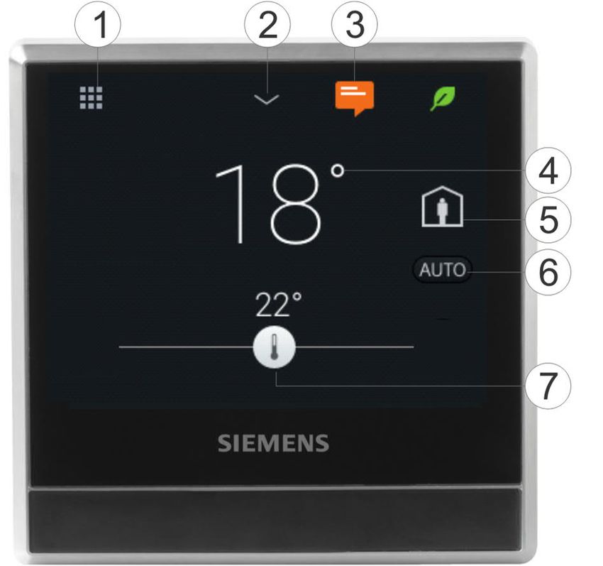
Normal display
1 Tap to display detailed information and additional settings.
2 Tap to display additional measurements, for example, outside air temperature. (Only if
external sensor is connected)
3 Tap to display notifications (only visible if applicable)
4 Room temperature
5 Tap to toggle between “At home” and “AWAY”.
6 Displays whether the thermostat is following a schedule ( ) or your setpoint
changes permanently ( ). Following a schedule can mean the following:
● If you are connected to a network and you have set your schedule, the thermostat
follows your schedule. Your temporary change of the temperature setpoint only
takes effect during the currently scheduled mode.
● If you are connected to a network but no schedule is set, the thermostat applies
the system’s default schedule. For more information about default schedules, see
Time-based schedules.
● Without network connection or valid time, the thermostat cannot retrieve schedule
information from the Cloud. It only works under the “Comfort” mode.
7 Tap or slide to change the room temperature setpoint. *
The thermostat is in heating mode – at some point, the relay will be energized,
depending on the heating demand and application type.
The thermostat is not in heating mode.
NOTICE! * There is a few seconds’ delay between the color change in the temperature
bar and the reaction of the relays.
5
Siemens A6V11562461_en--_b
Smart Infrastructure 2021-07-16NOTICE
After initial setup of the thermostat, the displayed room temperature may not be correct be-
cause the temperature sensors need time for calibration. Wait for at least one hour for the
thermostat to calibrate.
Idle display The RDS110.R screen switches to idle mode after 2 minutes of inactivity. The idle screen of
the RDS110.R can be displayed as a simple screen with basic room values, or as a blank,
black screen. The simple screen is the default setting.
1 Relative room humidity
2 Room air quality status: good , average , poor . (Displayed only if an
external air quality sensor is connected to the thermostat)
3 Outside air temperature (displayed only if an external temperature sensor is
connected to the thermostat)
4 Green leaf: Energy-optimized mode.
Red leaf: Tap to restore the energy-optimized mode.
5 Room temperature
NOTE: The icons displayed in idle mode may differ if you’ve connected external sensors to
your thermostat. For example, the idle screen may display room air quality status or outside
air temperature if a related external sensor is connected to the thermostat. However, the rel-
ative room humidity value and green leaf indication are always displayed on the idle screen.
To set idle display
a) On the Home screen, tap , then tap until the “Settings” page displays.
b) Tap > , and then tap or to set the idle screen as pure blank or with values.
6
Siemens A6V11562461_en--_b
Smart Infrastructure 2021-07-16Type summary
Product number Stock number Description
RDS110.R S55772-T103 Smart Thermostat Wireless
Ordering
● When ordering, indicate product number, stock number and description.
● Order valve actuators separately.
Inbox items
Items Quantity
Thermostat (front and rear) 1
Metallic mounting plate 1
Set of screws and plastic insert 1
Quick guide 1
Mounting instructions 1
Activation code sticker 1
Wiring sticker 1
Equipment combinations
Receiver
Type of unit Product number Stock number Datasheet*
Smart Thermostat Receiver RCR114.1 S55772-T104 A6V11562464
Actuator
Type of unit Product number Stock number Datasheet*
Radiator valve act. THREAD SSA911.01TH S55181-A101 A6V11739247
Remote sensors
Type of unit Product no. LG- Pt1000 NTC 10k DC 0…10 V Datasheet*
Ni1000 at 0 °C at 25 °C
at 0 °C
Room temperature sensors
- Wall-mounted QAA24 x CM1N1721
QAA2012 x CE1N1745
QAA2030 x CE1N1745
7
Siemens A6V11562461_en--_b
Smart Infrastructure 2021-07-16Type of unit Product no. LG- Pt1000 NTC 10k DC 0…10 V Datasheet*
Ni1000 at 0 °C at 25 °C
at 0 °C
QAA2061 x CE1N1749
QAA2061D2) x CE1N1749
- Flush-mounted1) AQR2531AN x CE1N1408
W
AQR2532NN x CE1N1411
W
- Concealed QAA64 x CM1N1722
(vandal-proof)
Outdoor temperature sensors
QAC22 x CE1N1811
QAC2012 x CE1N1811
QAC2030 x CE1N1811
QAC3161 x CE1N1814
Cable temperature sensors
QAP21.3 x CE1N1832
QAP22 x CE1N1831
QAP21.3/800 x CE1N1832
0
QAP2012.150 x CE1N1831
QAP1030.200 x CE1N1831
Room humidity sensors
- Wall-mounted QFA2000 Owing x CE1N1857
when
mountin
gunit
- Wall-mounted QFA2020 x (T) x (r.h.) CE1N1857
including
temperature QFA2060 x (T+r.h.) CE1N1857
QFA2060D2) x (T+r.h.) CE1N1857
- Flush-mounted1) AQR2534AN x (T) x (r.h.) CE1N1410
including W
temperature + AQR2540Nx
AQR2535NN x (T+r.h.) CE1N1410
W
+ AQR2540Nx
Indoor air quality sensors
8
Siemens A6V11562461_en--_b
Smart Infrastructure 2021-07-16Type of unit Product no. LG- Pt1000 NTC 10k DC 0…10 V Datasheet*
Ni1000 at 0 °C at 25 °C
at 0 °C
- CO2 QPA2000 x 149-910
- VOC + CO2 QPA2002 x 149-910
QPA2002D1) x 149-910
- CO2 including QPA2060 x(CO2+T) 149-910
temperature
QPA2060D1) x(CO2+T) 149-910
- Duct-mount CO2 QPM2100 x 149-909
- Duct-mount VOC QPM2102 x 149-909
+ CO2
- Duct-mount CO2 QPM2160 x(CO2+T) 149-909
including
temperature
- VOC QPA1000 x CE1N1961
Condensation monitors
- Condensation QXA2100 A6V107410
monitor 72
- Condensation QXA2101 A6V107410
monitor with offset 72
sensor
* The documents can be downloaded from http://siemens.com/bt/download by specifying the
product number as shown in the above table.
1) Requires a mounting plate and/or design frames.
2) With digital display.
Accessories (Optional)
Type of unit Product no. Datasheet*
White decorative frame and metallic ARG100.01 A6V11190640
mounting plate for installation on S55772-T102
rectangular conduit box (1 set)
NOTE: Accessories are not included with the unit and should be ordered separately.
* The documents can be downloaded from http://siemens.com/bt/download by specifying the
product number as shown in the above table.
9
Siemens A6V11562461_en--_b
Smart Infrastructure 2021-07-16Product documentation
Topic Title Document ID
Mounting and installation RDS110.R Mounting instruction A6V11562441
Installation and operation RDS110.R User guide A6V11562455
Startup wizard RDS110.R Quick guide A6V11562445
CE declaration A6V11802452
Product environmental declaration A6V11806767
Related documents such as environmental declarations, CE declarations etc., can be down-
loaded from http://siemens.com/bt/download.
Notes
Security
CAUTION
National safety regulations
Failure to comply with national safety regulations may result in personal injury and property
damage
● Observe any national provisions and comply with appropriate safety regulations.
Engineering
See the product documentation for information on engineering, selection and sizing connect-
ing cables for supply voltage and field devices.
Installation
The mounting plate of the thermostat can be installed on CEE/VDE conduit boxes and on
square boxes 75 x 75 mm. For installation on a rectangular conduit box (for example 105 x
72 mm), accessory ARG100.01 must be ordered, which includes a white decorative frame
and a bigger mounting plate.
WARNING
No internal line protection for supply lines to external consumers
Risk of fire and injury due to short-circuits
● Adapt the line diameters as per local regulations to the rated value of the installed over-
current protection device.
● The AC 230 V mains supply line must have an external circuit breaker with a rated cur-
rent of no more than 10 A.
● Use only AC 230 V isolated wired cables, as the conduit box carries AC 230 V mains
voltage.
● Inputs X1-M-X2: Several switches may be connected in parallel. Consider the overall
maximum contact sensing current of the switch rating.
● Disconnect from power supply before removing the thermostat cover.
10
Siemens A6V11562461_en--_b
Smart Infrastructure 2021-07-16Commissioning
See the Quick guide and User guide (see Product Documentation) to configure your device.
Commissioning includes the following:
● Internet connection
● Application setup
● Account registration and device pairing
NOTE:
Before configuring your thermostat, ensure that you are connected to the Internet, have a
valid email address, and a smartphone.
Mounting
Note the following when mounting the unit:
● The devices are suitable for wall mounting.
● Recommended height: 1.50 m above the floor.
● Do not mount the devices in recesses, on shelves, behind curtains or doors, or above or
near heat sources.
● Avoid direct sunlight.
● Seal the conduit box or the installation tube if any, as air currents can affect sensor read-
ings.
● Observe to allowed ambient conditions.
Operation
End users can operate the thermostat directly on the touch screen, or download the mobile
app “Siemens Smart Thermostat RDS”and perform operations on their smartphones, includ-
ing:
● Creating and managing accounts
● Setting the operating mode (Auto, away, home, manual)
● Changing the room temperature (by setting new setpoints)
● Setting a weekly schedule (heating and domestic hot water)
● Opting for geo-fencing
● Selecting the Green leaf (switching to energy-optimized operation)
● Viewing temperature, humidity and heat demand trends
Supported smartphone types are as follows:
11
Siemens A6V11562461_en--_b
Smart Infrastructure 2021-07-16Operating system
OS OS version App store
iOS iOS 12 or above App store®
Android AndroidTM 10.0 or above Google PlayTM
Maintenance
The thermostat is designed for maintenance-free operation.
Disposal
The device is considered an electronic device for disposal in accordance
with the European Guidelines and may not be disposed of as domestic
garbage.
● Dispose of the device through channels provided for this purpose.
● Comply with all local and currently applicable laws and regulations.
Warranty
Technical data on specific applications are valid only together with Siemens products listed
under "Equipment combinations". Siemens rejects any and all warranties in the event that
third-party products are used.
Radio equipment directive
The equipment is using harmonized frequency in Europe and complies with the Radio
Equipment Directive (2014/53/EU, formerly 1999/5/EC).
12
Siemens A6V11562461_en--_b
Smart Infrastructure 2021-07-16Technical data
Power supply
Power supply
Operating voltage AC 230 V (+10% / -15%)
Frequency 48…63 Hz
Power consumption Max. 9 VA
Standby power consumption (LCD off) 1.6 W
Maximum external supply line fusing 10 A circuit breaker
Radio parameters
Radio parameters
Frequency band 2.4…2.4835 GHz
Maximum radio-frequency power 18 dBm
WLAN standard IEEE 802.11b/g/n (HT20)
WLAN channel 1~13
Frequency band 2.4…2.4835 GHz
Maximum radio-frequency power 15 dBm
Thread standard IEEE 802.15.4
Thread channel 11-26
13
Siemens A6V11562461_en--_b
Smart Infrastructure 2021-07-16Inputs
Connections to multifunctional inputs X1 - M - X2
Passive temperature sensors
- Cable length max. (copper cable section) 90 m (1.5 mm2 wire), 70 m (1 mm2 wire)
60 m (0.75 mm2 wire), 40 m (0.5 mm2 wire)
- NTC type NTC10K at 25 °C
Room temperature range 0…50 °C
Outdoor temperature range -50…80 °C
Floor temperature range* -50…80 °C
- Ni type Ni1000 at 0 °C
Room temperature range 0…50 °C
Outdoor temperature range -50…80 °C
Floor temperature range* -50…80 °C
- Pt type Pt1000_375/Pt1000_385 at 0 °C
Room temperature range 0…50 °C
Outdoor temperature range -50…80 °C
Floor temperature range* -50…80 °C
Active DC 0 V ...10 V sensors Min./max. configurable via parameters
- Room temperature range (default) 0…50 °C
- Outdoor temperature range (default) -50…80 °C
- Humidity range (default) 0…100%
- CO2/VOC range (default) 0…2000 ppm
- Floor temperature range* -50…80 °C
Digital contacts
- Operating action Selectable NO/NC
- Contact sensing DC 14…40 V, 8 mA (typ.)
- Parallel connection Maximum 20 thermostats per switch
- Input function Selectable
* Available when electric heating is energized.
Operational data
Setpoint setting range
0…50 ℃
12…35 ℃ (default)
Built-in room temperature sensor
Temperature range Accuracy at 25 ℃ Display resolution
0…50 ℃ ±0.5 K 0.5 K
14
Siemens A6V11562461_en--_b
Smart Infrastructure 2021-07-16Built-in room humidity sensor
Humidity range Accuracy at 25 ℃ Display resolution
0%...100% ±5% r.h. 1%
Connections
Interfaces
Micro USB A service port is limited to firmware upgrades
and onsite diagnosis by professionals.
Wiring connections
Screw terminal Solid wires or prepared stranded wires:
Maximum 1 × 0.5... 2.5 mm2 (14…20 AWG)
Conformity
Ambient conditions and protection classification
Safety class as per EN60730 Class II
Degree of protection of housing as per EN IP30
60529
Classification as per EN 60730
Function of automatic control devices Type 1
Operation altitude < 3000 m
Degree of contamination 2
Overvoltage category III
Climatic ambient conditions
Transport (packaged for transport) as per EN Transport/ Storage:
60721-3-2 Temperature -25...60 °C (-13... 158 °F)
Storage as per EN 60721-3-1 Air humidity 5...95% r.h. (non-condensing)
Operation as per EN 60721-3-3 Operation:
Temperature 0...50 °C (23... 122 °F)
Air humidity 5...95% r.h. (non-condensing)
Mechanical ambient conditions
Transport as per EN 60721-3-2 Class 2M2
Operation as per EN 60721-3-3 Class 3M2
15
Siemens A6V11562461_en--_b
Smart Infrastructure 2021-07-16Standards, directives and approvals
EU conformity (CE) A6V11802452*)
RCM conformity A6V11231674*)
Environmental compatibility The product environmental declaration
A6V11806767*) contains data on
environmentally compatible product design
and assessments (RoHS compliance,
materials composition, packaging,
environmental benefit, disposal).
*) The documents can be downloaded from http://siemens.com/bt/download.
Eco design and labeling directives
Based on EU Regulation 813/2013 (Eco design directive) and 811/2013
(Labelling directive) concerning space heaters, combination heaters, the
following classes apply:
Application with On/Off operation of a heater Class I Value 1%
PWM (TPI) room thermostat, for use with Class IV Value 2%
On/Off output heaters
General data
General
Dimension See Dimensions
Weight Thermostat with package, user document and 534 g
accessory
Thermostat 219 g
Color Silver plating
Housing: Pantone black
Diagrams
Connection terminals
16
Siemens A6V11562461_en--_b
Smart Infrastructure 2021-07-16NOTICE! External loads on L and N are not allowed.
Terminal Use
L, N Operating voltage AC 230 V
X1, X2, M Multifunctional inputs
Wiring diagrams
L, N Operating voltage AC 230 V B1, B2 External sensors
X1, X2, M Multifunctional inputs S1, S2 External switches
17
Siemens A6V11562461_en--_b
Smart Infrastructure 2021-07-16Application examples
Applications
Gas boiler Electric boiler
(with RCR114.1) (with RCR114.1)
Radiator with valve Floor heating with valve
(with SSA911.01.TH) (with RCR114.1)
Radiator with pump Floor heating with pump
(with RCR114.1) (with RCR114.1)
Electric radiator Electric floor heating
(with RCR114.1) (with RCR114.1)
18
Siemens A6V11562461_en--_b
Smart Infrastructure 2021-07-16Applications
Fan with electric heating Domestic hot water boiler
(with RCR114.1) (with RCR114.1)
N1 RDS110.R
N2 RCR114.1
F1, F2 Limit thermostats
K1 Heat generator (example, boiler)
Y1 Magnetic valve
Y2 Domestic hot water boiler
Y3 Valve
Y4 SSA911.01TH
M1 Circulating pump
Dimensions
RDS110.R
Front and rear modules Metallic mounting plate
19
Siemens A6V11562461_en--_b
Smart Infrastructure 2021-07-16ARG100.01
White decorative frame Metallic mounting plate
Revision history
Edition Date Software version Changes Section Pages
2 July 2021 45.4.46 Removed information about window Installation 10
contact.
1 September 2019 45.4.44 New document --- ---
20
Siemens A6V11562461_en--_b
Smart Infrastructure 2021-07-16Issued by
© Siemens Switzerland Ltd, 2021
Siemens Switzerland Ltd
Technical specifications and availability subject to change without notice.
Smart Infrastructure
Global Headquarters
Theilerstrasse 1a
CH-6300 Zug
+41 58 724 2424
www.siemens.com/buildingtechnologies
Document ID A6V11562461_en--_b
Edition 2021-07-16You can also read