JOY SR EC AO2DO | SR EC 3AO RS485 Modbus - Thermokon
←
→
Page content transcription
If your browser does not render page correctly, please read the page content below

» JOY SR EC AO2DO | SR EC 3AO RS485 Modbus
 Electronic Fancoil Thermostat
 (from Version 2.6.x)

 Datasheet
 Subject to technical alteration
 Issue date: 26.02.2021 • A122

 » APPLICATION
 The fancoil controller with radio receiver in high-quality design is used for individual temperature control and control of fancoil units in hotels, offices
 and living rooms. Two configurable inputs can be used as sensor input, room occupancy or energy lock. In addition to wired valve actuators r,
 sensors and actuators can also be controlled by radio. In addition, as an alternative to wired sensors, an external radio temperature sensor, radio
 motion detector, a radio temperature sensor for changeover function and radio window contacts/handles can be learnt in. The override by radio is
 possible by means of higher-level controller profile and cable-bound via Modbus. Radio and wired sensors and actuators are processed identically
 and can be used in any combination. This guarantees individual and energy-efficient room air conditioning. The device (front of glass in white or
 black) has a monochrome display and touch-sensitive control buttons. It has a timer with three time channels of four time periods each. Mounting
 is designed for a flush-mounted box. For hotel applications, the device offers the option of an additional zone (bathroom heating) in conjunction
 with room temperature sensor and radio actuator SAB.

 JOY SR Fancoil EC AO2DO (85..260 V ~)

 Modern fan coil room thermostat to control fan coil units with EC fans. It is suitable for 2- and 4-pipe systems. It has 2 relays and 1 analogue output
 0-10V (heating valve, cooling valve and EC fan). The device combines a modern design with a 2,5” LCD and a touch-sensitive surface, 3 time
 program options each with 4 time periods options.
 JOY SR Fancoil EC 3AO (24 V ~/=)
 Modern design, flush mounting fan coil room thermostat. Used for individual control of temperature in commercial, industrial and residential
 buildings. It is tailored for two-pipe and four-pipe fan coil units with two-wire electric valves or controlling a 6-way valve. The device combines a
 modern design with a 2,5” LCD and a touch-sensitive surface, 3 time program options each with 4 time periods options.

 » SECURITY ADVICE – CAUTION
                 The installation and assembly of electrical equipment should only be performed by authorized personnel.
                 The product should only be used for the intended application. Unauthorised modifications are prohibited! The product must not be
                 used in relation with any equipment that in case of a failure may threaten, directly or indirectly, human health or life or result in
                 danger to human beings, animals or assets. Ensure all power is disconnected before installing. Do not connect to live/operating
                 equipment.
                 Please comply with
                 •        Local laws, health & safety regulations, technical standards and regulations
                 •        Condition of the device at the time of installation, to ensure safe installation
                 •        This data sheet and installation manual

Thermokon Sensortechnik GmbH, Platanenweg 1, 35756 Mittenaar, Deutschland · tel: 02778/6960-0 · fax: -400 · www.thermokon.de · email@thermokon.de
                                            JOY_SR Fancoil_Modbus_Datasheet_en.docx © 2021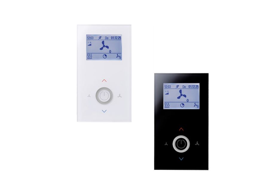
Page 2 / 12                                                                                                               Issue date: 26.02.2021

 » NOTES ON DISPOSAL
                 As a component of a large-scale fixed installation, Thermokon products are intended to be used permanently as part of a building
                 or a structure at a pre-defined and dedicated location, hence the Waste Electrical and Electronic Act (WEEE) is not applicable.
                 However, most of the products may contain valuable materials that should be recycled and not disposed of as domestic waste.
                 Please note the relevant regulations for local disposal.

 » REMARKS TO ROOM SENSORS
 Location and Accuracy of Room Sensors

 The room sensor should be mounted in a suitable location for measuring accurate room temperature. The accuracy of the temperature
 measurement also depends directly on the temperature dynamics of the wall. It is important, that the back plate is completely flush to the wall so
 that the circulation of air occurs through the vents in the cover. Otherwise, deviations in temperature measurement will occur due to uncontrolled
 air circulation. Also the temperature sensor should not be covered by furniture or similar devices. Mounting next to doors (due to draught) or
 windows (due to colder outside wall) should be avoided. The temperature dynamics of the wall will influence the temperature measurement. Various
 wall types (brick, concrete, dividing and hollow brickwork) all have different behaviours with regards to thermal variations.
 Surface and Flush Mounting
 The temperature dynamics of the wall influence the measurement result of the sensor. Various wall types (brick, concrete, dividing and hollow
 brickwork) have different behaviours with regard to thermal variations. A solid concrete wall responds to thermal fluctuations within a room in a
 much slower way than a light-weight structure wall. Room temperature sensors installed in flush boxes have a longer response time to thermal
 variations. In extreme cases they detect the radiant heat of the wall even if the air temperature in the room is lower for example. The quicker the
 dynamics of the wall (temperature acceptance of the wall) or the longer the selected inquiry interval of the temperature sensor is the smaller the
 deviations limited in time are.

 » PRODUCT TESTING AND CERTIFICATION
                 Declaration of conformity
                 The declaration of conformity of the products can be found on our website https://www.thermokon.de/.

 » DIAGNOSTICS MENU
 To access the diagnostics menu, select the header in the startscreen of the parameter menu, and press the ENTER key. Here you will find various
 information, such as device type, software version, state of the inputs and outputs and controller state (current manipulated variable).

 » MOUNTING ADVICES
 Plasterboard boxes shall be covered by wall paper or paint to avoid that the plasterboard box's front rim will be partially visible underneath JOY.
 Maybe consider using white plasterboard boxes (i.e. Kaiser 9063-77)

Thermokon Sensortechnik GmbH, Platanenweg 1, 35756 Mittenaar, Deutschland · tel: 02778/6960-0 · fax: -400 · www.thermokon.de · email@thermokon.de
                                            JOY_SR Fancoil_Modbus_Datasheet_en.docx © 2021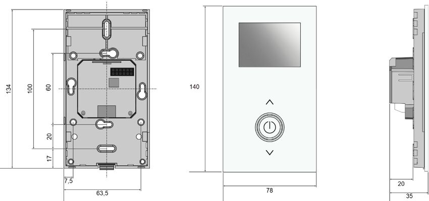
Issue date: 26.02.2021                                                                                                                      Page 3 / 12

 » APPLICATION NOTICE
 Boot Loader

 A bootloader integrated in the device, makes it possible to install a new application (update, upgrade) using a MicroSD card. To insert the SD card,
 the upper part must be removed. If the boot loader is activated, the ring illumination blinks in a 1s cycle, while display is not triggered! After
 recognition of a MicroSD card with a valid application the update process is started. Now, ring illumination blinks fast in a 300ms cycle. After a
 successful update process (Duration approx. 20-30 seconds!), the new application is started automatically. Afterwards, SD card have to be
 removed! A firmware update can also performed via the Modbus interface. In this case, the program "Thermokon Bootloader" (as of version 2.0.0)
 and the corresponding firmware file are needed.
 SD-Card
 The parameterization of the receive channels for EasySens transmitter (i.e. SRW0x window contact) and the configuration of the device can be
 done with a MicroSD card. You can create a configuration file with the Thermokon tool uConfig. This means that sensors can be learned-in without
 having to press the LRN buttons of the relevant sensors.
 The MicroSD card can also be used to read a configuration from the JOY. The MicroSD card can be plugged in during the current configuration or
 it can be used after the configuration has been completed. If a MicroSD card is inserted during the configuration, each learn / learn process is
 wrote directly into the file. If the MicroSD card is inserted after the configuration, the configuration file is automatically created on the card after a
 restart.
 Note: EasySens receivers such as SAB or actuators need the ID of the transmitter (Joy) via manually initiated teach-in telegram.Only MicroSD
 cards formatted in the FAT file system can be used! NTFS and exFAT file systems are not supported.

 Software manual

 A detailed description of the parameter and the configuration software uConfig can be downloaded from our website.

 » CONFIGURATION VIA UCONFIG | MICROSD-CARD OR MODBUS
                    Configuration software:
                    uConfig | Windows 10 is required to use the uConfig configuration software

                    The JOY room thermostat can be parameterised using the uConfig configuration software. An SD card is used to transfer the
                    created configuration file to the device. For BUS devices, a live configuration can also be performed via the BUS interface.
                    The online installer for the configuration software can be found in our download center. The installer retrieves all necessary files
                    and plug-ins from our web server. In this version an update function is integrated in the software.
                    → Download Online-Installer

                    A separate offline installer is available for installations on PCs/Notebooks without internet connection. For an update of the
                    software a recurring reinstallation is necessary.
                    → Download Offline-Installer

Thermokon Sensortechnik GmbH, Platanenweg 1, 35756 Mittenaar, Deutschland · tel: 02778/6960-0 · fax: -400 · www.thermokon.de · email@thermokon.de
                                            JOY_SR Fancoil_Modbus_Datasheet_en.docx © 2021
Page 4 / 12                                                                                                                  Issue date: 26.02.2021

 » TECHNICAL DATA
  Measuring values                  temperature, humidity (optional)

  Network technology                RS485 Modbus

  Radio technology                  EnOcean (IEC 14543-3-10), transmission power
Issue date: 26.02.2021                                                                                                             Page 5 / 12

 » INFORMATION ABOUT EASYSENS® (RADIO) / AIRCONFIG GENERAL USAGE
                              EasySens® - airConfig
                              Basic information about EasySens® radio and about general usage of our airConfig software, please download
                              from our website.

 » OVERVIEW OF THE RADIO TELEGRAMS
                              EEP
                              The structure of the data contained in the telegram can be found in the EEP (EnOcean equipment profile) list
                              provided by the EnOcean Alliance.

 » SUPPORTED PROFILES

 Receiving profiles
                                                                                                                                       LCD/
                                                                                                                        Max.
  EnOcean-EEP        Type        Direction                   Description                    Thermokon Devices                        Funktion
                                                                                                                       Quantity
                                                                                                                                     s-gruppe
     F6-02-01         RPS           Rx                     EnOcean button                          Diverse                 1            RPS

     D5-00-01         1BS           Rx                    Windows contacts                         SRW01                               SRW
                                                                                                                        max.5
     F6-10-00         RPS           Rx                     Windows handle                          SRG02                               SRG

     A5-02-06         4BS           Rx                   Temperature 0-50°C                                                             VFG
                                                                                           SR65 VFG, SR65 TF,
                                                                                                                           1
                                                                                            SR65 AKF, SR65
     A5-02-16         4BS           Rx                   Temperature 0-80°C                                                             VFG
                                                           Room Sensor                    SR04, LC-SR04, SR07,
     A5-02-05         4BS           Rx                                                                                                  EXT
                                                        (Temperature 0-40°C)                      SR65
                                                                                                                           1
                                                       (Room Operating Panel)             SR07P, SR04P, SR06
     A5-10-03         4BS           Rx                                                                                                 WRF
                                                        Temperatur, Set Point                    2T/2T+
                                                                                            SR-MDS Solar, SR-
                                                            Room Sensor
     A5-07-01         4BS           Rx                                                     MOC Solar, SR-MOW                           OCC
                                                            (Occupancy)
                                                                                                  Solar                 max. 3
                                                           Room Sensor
     A5-08-01         4BS           Rx                                                            SR-MDS                               OCC
                                                   (Occupancy, Light, Temperature)
     F6-04-01         RPS           Rx                         Keycard                      SR-KCS02, SR-KCS               1            KEY

     A5-20-01         4BS          Rx/Tx                         SAB                           SAB+, SAB05              max. 6          SAB
                                                         Superior Control Unt
     A5-20-12         4BS           Rx            (Fan. Set Point, Controller, Energy                                      1            SUP
                                                    Hold OFF/Dew point, Occup)

 Transmitting profiles
    EnOcean-                                                                                                            Max.
                     Type        Direction                                 Descripton                                                   LCD
      EEP                                                                                                              Quantity
    A5-10-02                                          Valid from Version 2.1.1 (up to 2.1.0: A5-10-01)
                      4BS           Tx
    (V2.1.1 +)                                       Room operating panel (Fan,Temp, Sollwert, Occup)
                                                                                                                          1            WRF
    A5-10-06                                          Valid from Version 2.1.1 (up to 2.1.0: A5-10-05)
                      4BS           Tx
    (V2.1.1 +)                                         Room operating panel (Temp, Sollwert, Occup)
                                                Temperature Controller (Fan, Set point, alarming, Controller state,
     A5-11-02         4BS           Tx                                                                                    1             OUT
                                                                  Energy Hold OFF, Occup)
     A5-20-01         4BS          Rx/Tx                                       SAB                                    max. 5+1          SAB

Thermokon Sensortechnik GmbH, Platanenweg 1, 35756 Mittenaar, Deutschland · tel: 02778/6960-0 · fax: -400 · www.thermokon.de · email@thermokon.de
                                            JOY_SR Fancoil_Modbus_Datasheet_en.docx © 2021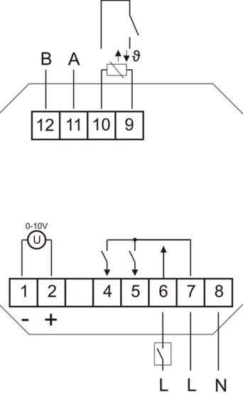
Page 6 / 12 Issue date: 26.02.2021
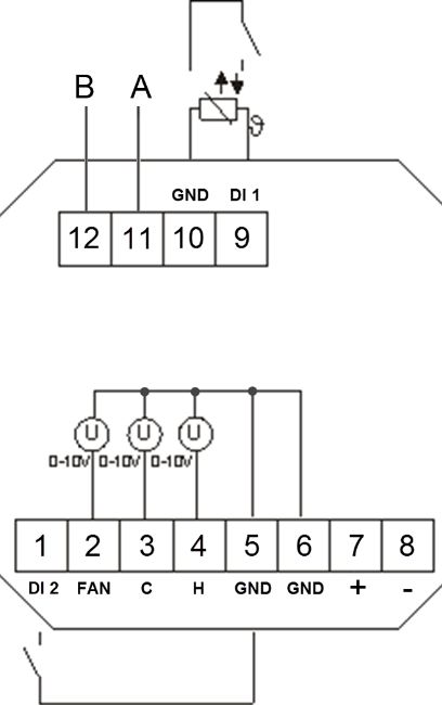
» CONNECTION PLAN
JOY FANCOIL EC AO2DO (85..260 V ~) JOY FANCOIL EC 3AO (24 V ~/=)
1 EC Fan GND 1 Digital Input 2
2 EC Fan (0..10 V) 2 EC Fan (0..10 V)
3 Cooling (0..10 V) or 6-way valve
4 Cooling 4 Heating (0..10 V) or 6-way valve
5 Heating 5 GND DI 2
6 Digital Input 2 (230V) 6 GND
7L 7 24 V = (±10%) or 24 V ~ (±10%)
8N 8 GND
12 Modbus B 12 Modbus B
11 Modbus A 11 Modbus A
10 GND DI 1 10 GND DI 1
9 Digital Input 1 (or NTC10K) 9 Digital Input 1 (or NTC10K)
Note: Parallel connection of the potential-loaded inputs is not permitted!
If the operating mode (change-over DI) of several devices is to be switched together by one contact, the potential-free 230V input must be used
(DI2, only possible with the 230V version). It must be ensured that the same phase is used for jointly switched devices.
Thermokon Sensortechnik GmbH, Platanenweg 1, 35756 Mittenaar, Deutschland · tel: 02778/6960-0 · fax: -400 · www.thermokon.de · email@thermokon.de
JOY_SR Fancoil_Modbus_Datasheet_en.docx © 2021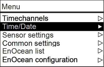
Issue date: 26.02.2021                                                                                                                       Page 7 / 12

 » FUNCTION DESCRIPTION – CONTROLLER/FAN STAGES

    JOY FANCOIL EC AO2DO (85..260 V ~)                     JOY FANCOIL EC 3AO (24 V ~/=)

               PI controller (PWM) &
              2-point/3-point controller                            PI controller (0..10 V)
                   (configurable)

 Fan stages (all types)

 In automatic mode the fan speed is linked to the controller. The assignment of the fan stage to the control (heating / cooling, only heating, only
 cooling) is freely selectable. To ensure that the fan motor starts reliably, a period of time can be configured in which the fan starts with maximal
 value. Using one or more time channels, the fan control have to be set per timechannel and per period. Via the touch surface the user has the
 option to override the settings of the device every time. When the next time channel starts, the fan speed is set to the configured value. The fan is
 set to automatic mode when the user changes the occupancy state (occupied↔unoccupied).

 Heating/ cooling with PI-controller (PWM) (only EC AO2DO)

 The time response of the PI control loop depends on the control parameters xp for the proportional area and tn for the reset time of the integral
 range. In case of an error, the P portion immediately changes the position value proportionally to the error variable, while the integral portion
 takes effect after a certain time.
 The resulting actuating variable is output as a pulse-width-modulated signal directly to the outputs.

 Heating/ cooling with 2-point-/ 3-point-controller (only EC AO2DO)

 In the case of temperature control, the 2-point controller only knows the switching states heating ON and heating OFF. The 3-point controller also
 knows the switching state of cooling. Two - and three-point controller work with a hysteresis.

 Heating/ cooling with PI-controller (0..10 V) (only EC 3AO)
 The time response of the PI control loop depends on the control parameters xp for the proportional area and tn for the reset time of the integral
 range. In case of an error variable, the P portion immediately changes the position value proportionally to the error variable, while the integral
 portion takes effect after a certain time.
 The resulting manipulated variable is output as an analogue 0..10 V signal directly to the outputs.

 EC Fan automatic mode with PI-controller (only EC 3AO and EC AO2DO)
 (for EC AO2DO with two-point/three-point controller, the temperature range for controlling the 0..10 V EC fan is parameterised separately)

 The 0..10 V (0..100%) control of the fan is proportional to the calculated manipulated variable of the PI controller.
 Example:
 Calculated actuating variable 65% → Fan control with 6,5 V.
 Calculated actuating variable 22% → Fan control with 2,2 V.

 EC Fan manual with PI-controller (only EC 3AO and EC AO2DO)

 Up to 5 steps (steps) can be set using the configuration software. The set number of steps is divided linearly to the manipulated variable of
 0..100%.
 Example:
 Max. steps (stages) = 5                      Max. steps (stages) = 3
 Stage 1 = 20%                                Stage 1 = 33%
 Stage 2 = 40%                                Stage 2 = 66%
 Stage 3 = 60%                                Stage 3 = 100%
 Stage 4 = 80%
 Stage 5 = 100%

Thermokon Sensortechnik GmbH, Platanenweg 1, 35756 Mittenaar, Deutschland · tel: 02778/6960-0 · fax: -400 · www.thermokon.de · email@thermokon.de
                                            JOY_SR Fancoil_Modbus_Datasheet_en.docx © 2021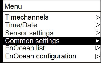
Page 8 / 12                                                                                                             Issue date: 26.02.2021

 » FUNCTION DESCRIPTION - BUTTONS
 On the touch surface, there are adjustment options for setpoint and fan speed regulation.

                                                                        A
                  The Buttons “Fan speed
                  UP” (B) and “Fan speed
                DOWN” (D) can set the fan
                 speed. 3 seconds without
                any interaction, the display           D                E                    B             The buttons (A) and (C)
                                                                                                          change the setpoint in the
               returns back to main screen.                                                                 range ± 3 ° C (default
                  While pressing of these                                                                   setting, configurable).
                 buttons, the white LED of
                the Power-button (E) lights
                   up for visual feedback.                             C

 The Power button (E) can be used to switch the room thermostat to standby mode (not possible if the Keycard switch function is used!) If the key
 is used as a presence key at the same time, the key must be pressed for at least 3s, in all other cases a short press is sufficient. In standby
 mode the display and all outputs are switched off (controller deactivated). The frost and heat protection monitoring remains active. Modbus
 registers can still be read (e.g. room temperature).

 Main screen/ Value display

 The Display shows the measured value of the internal sensor. The value of an external sensor will be shown if connected and configured
 accordingly. The room thermostat controls in this case according to the external sensor.

               Header →

      Value display →
     (Humidity optional)

                Footer →

 Header
 In the header line, the time, weekday and date are displayed. In addition, the ECO info symbol (sheet) is displayed here when the ECO mode is
 switched on. It is possible to show an alarm symbol (exclamation mark) in the display. This symbol is located at the same position as the ECO
 symbol. Since the alarm symbol has a higher priority, it overwrites the ECO symbol.

 Footer - Symbols
 Depending upon the heating or cooling mode, occupancy or window contact status, the corresponding symbols will be shown in the footer. The
 symbol “active timechannel” will be shown only if active. To enable the symbols, the corresponding parameters must be set via the configuration
 software or Modbus.
  Occupancy

  Window contact/dewpoint

  Heating/Cooling

  Fan Speed

  Active timechannel

Thermokon Sensortechnik GmbH, Platanenweg 1, 35756 Mittenaar, Deutschland · tel: 02778/6960-0 · fax: -400 · www.thermokon.de · email@thermokon.de
                                            JOY_SR Fancoil_Modbus_Datasheet_en.docx © 2021
Issue date: 26.02.2021 Page 9 / 12
» CONFIGURATION VIA THE DISPLAY MENU
Buttons
The configuration menu is activated by simultaneously pressing the buttons “up” (A), “left”
A (D) and “right” (B) for at least 3 seconds. Menu navigation on the touch-surface is
performed by pressing the buttons “up” (A), “down” (C), “left” (D), “right” (B) or the power
button. Choose the desired parameter and press “right” (B) to open up the submenu. If no
entry is made for 8 minutes, the parameter menu is left automatically. To exit the menu
select the header line and press “left” (D).
D B
C
» MENU → TIME CHANNELS
In the Time Channels menu, setpoint and timer can be set. Up to 3 time channels with 4 time periods each can be parameterized. The time
channels are prioritised. Channel 3 has the highest priority. After selecting the line of the time channel to be edited, the next submenu is called up
with the "Right" key. It is possible to set any time period within one week in the first two lines with the "Left" (-)/ "Right"(+) keys. In addition, the
ECO mode is available in the menu sections. In ECO mode, the dead zone between heating and cooling is automatically set to the ECO dead
zone configured in the "General Settings" menu (default: 10 K).
» MENU → TIME/DATE
Time, Date and display format can be configured in the menu settings. The room thermostat is equipped with a real-time clock so that it
automatically adjusts for daylight-saving time. This function can be disabled in the datetime settings.
» MENU → SENSOR SETTINGS
Offset correction for internal and external sensor value. The temperature display can also be changed from °C to °F.
Thermokon Sensortechnik GmbH, Platanenweg 1, 35756 Mittenaar, Deutschland · tel: 02778/6960-0 · fax: -400 · www.thermokon.de · email@thermokon.de
JOY_SR Fancoil_Modbus_Datasheet_en.docx © 2021Page 10 / 12 Issue date: 26.02.2021
» MENU → COMMON SETTINGS
The common settings includes the brightness of the background lighting and the LED. Valve protection prevents the valves becoming ceased when
they are switched off for long periods. If the valve protection function is activated, a valve-check is carried out every Friday at 11:00 am for the
heating valve and 11:15 am for the cooling valve. The corresponding valve is triggered for 5 minutes, if not activated during the last 96 hours. The
dead band can be adjusted (default 10.0 K, see timechannels). The room thermostat has 3 outputs for fan control with up to 3 fan stages. The
amount of fan stages are configurable. By selecting “Factory setting”, the room thermostat will be reset and restore the device to factory default
settings.
» PARAMETER MENU – MODBUS INTERFACE
The configuration menu is activated by simultaneously pressing the buttons “up” (A) and “down” (C) for at least 5 seconds.
The menu is enabled during the first 60 minutes after switching on the supply voltage as long as the device is not actively involved in Modbus
communication. As soon as the device receives a valid request addressed to the device from a DDC, access to the menu is blocked. Without valid
communication, access is blocked after 60 minutes!
Modbus settings Address (default: 32)
Adjustable address (1-247)
Address -/+ 32
Baudrate -/+ 19200 Baud rate (default: 19200)
Parity -/+ Even 9600Bd | 19200Bd | 38400Bd | 57600Bd
Parity (default: even)
Non | odd | even
» MENU → ENOCEAN LIST | ENOCENAN CONFIGURATION
Two additional selection menus appear in the menu, and . The EnOcean list is a simple list display of
the EnOcean sensors that have been taught in, in addition to the list, further information on the individual sensors can be called up.
EnOcean list
All channels with the learned sensors or actuators are displayed in this list.
With , detailed information are displayed:
EnOcean configuration
In this menu item, the radio channels can be configured and individual information can be called up.
In the footer, various menu items can be selected with the LEFT /
RIGHT keys and the corresponding menu item is selected with the
ENTER key.
SAB valve actuators are learned in with the function
.
EXIT DELETE CHANNEL LEARN SENSOR SET ACTOR SHOW CHANNEL
The access to the menu can be protected with a password via Modbus. The login remains unlocked in the EnOcean
menu until 10 minutes after the last key press. Default password: 2030.
More detailed information for the configuration of the EnOcean channels can be found in the specification.
Thermokon Sensortechnik GmbH, Platanenweg 1, 35756 Mittenaar, Deutschland · tel: 02778/6960-0 · fax: -400 · www.thermokon.de · email@thermokon.de
JOY_SR Fancoil_Modbus_Datasheet_en.docx © 2021Issue date: 26.02.2021 Page 11 / 12
There are 20 channels available that can be assigned different functions. A channel can be configured as a receive channel, as a send channel or
as a message server (SAB communication).
6 channels can be configured with SAB valve actuator, one of these can be set with the bath function. For the SAB with the bath function, an
additional setpoint offset can be set. If SAB valve actuators are learned in, the analogue outputs to the internal controller remain active and can
also be used.
Functional Overview SAB
The profiles used are divided into functional groups:
SRW/SRG Window contact and window handle. Both have an influence on the window contact function and are linked to the digital
inputs or the Modbus default. Up to five sensors can be learned-in.
VFG Sensor for chngeover control. Only one changeover sensor can be learned in.
EXT/WRF Receiving channel: Temperature preset by an external room temperature sensor. Overrides the internal temperature
sensor. Max. one sensor can be learned in. An EnOcean room operating unit is displayed on the send channel.
OCC Up to 3 motion sensors can be learned in and affect the occupancy function. The last changed value
(Modbus,EnOcean, Button) will be accepted. If several EnOcean motion sensors have been learned-in, the "ROOM
UNOCCUPIED" value will only be accepted once all sensors have signaled "ROOM UNOCCUPIED".
KEY Controls the internal keycard function. When learning a key card switch, the card must not be plugged in AND pulled
immediately during the learn-in process. It is necessary to wait at least 5 seconds until the second action is performed
with the card. Only then will the switch be assigned as key card switch, otherwise it will be learned in as a radio rocker
switch (function group RPS).
SUP A superior control unit to override the internal functions.
SAB Up to 6 SAB´s can be learned in. One pcs. can be assigned with the „Bath“ function. The other channels can be used
(5+1 Bath) optionally for heating or cooling. For each SAB channel, an offset for the setpoint can be configured via Modbus.
OUT Only in direction of transmission. A controller status (A5-11-02) every 15 minutes (configurable) and with every change
of any value.
Thermokon Sensortechnik GmbH, Platanenweg 1, 35756 Mittenaar, Deutschland · tel: 02778/6960-0 · fax: -400 · www.thermokon.de · email@thermokon.de
JOY_SR Fancoil_Modbus_Datasheet_en.docx © 2021Page 12 / 12 Issue date: 26.02.2021
» INPUTS
Up to 2 inputs are configurable for functions such as windows contact, dew point, occupancy, change-over or external sensor option.
The overview of possible combinations can be found in the software specification of the JOY.
Sensor (NTC10K)
The value of an external sensor will be shown if connected and configured accordingly. In this case, the room thermostat controls according to the
external sensor. Alternatively, an external temperature sensor can be used at the universal input to protect floor heating. If a configured temperature
is exceeded, the heating sequence is suspended.
Change-Over DI
Which controller is active depends on the state of the Change-Over contact. (Factory default: contact open heating controller active, contact closed
cooling controller active). The terminals 4 and 5 are used as outputs for heating rsp. cooling.
Change-Over Sensor
The Change-Over Sensor is used for switching between heating and cooling mode automatically. If the temperature is below 22 ° C, the controller
is in cooling mode. If it is above 25 ° C, it is a heating mode.
If an input is configured as a change-over, the room thermostat is automatically in 2-pipe operating mode and both outputs (terminals 4 and 5) are
used as outputs for heating rsp. cooling.
Window contact/Energy hold off
If a window contact is enabled via the digital input, the reference will switch to a setback set point (Heat SP/Cool SP).
Dewpoint
An active dewpoint contact locks the cooling controller.
Occupancy
If occupancy-function is active, the symbol will be displayed automatically. In state of “unoccupied” the heating set point is reduced by 2K (default
setting) rsp. the cooling set point raised by 2K.
Keycard-Switch
When the card is not inserted, the device is switched in sleep mode. Operation of the keys is locked, the display is switched off and the controller
adjusts to the nominal values of the "unoccupied"-State.
Alarm contact
An alarm symbol can be shown in the header of the display. The backlight flashes when the alarm is active. This symbol is in the same position as
the ECO symbol. The alarm symbol has a higher priority and overwrites the ECO symbol!
» DIMENSIONS (MM)
» ACCESSORIES (OPTIONAL)
Converter RS485 Modbus - USB Item No. 668293
Decorative frame pure white for JOY Item No. 681452
Decorative frame black for JOY Item No. 740951
MicroSD card 2GB Item No. 500098
Thermokon Sensortechnik GmbH, Platanenweg 1, 35756 Mittenaar, Deutschland · tel: 02778/6960-0 · fax: -400 · www.thermokon.de · email@thermokon.de
JOY_SR Fancoil_Modbus_Datasheet_en.docx © 2021You can also read