An Eclipse plug-in for Public Administration software system modelling and simulation
←
→
Page content transcription
If your browser does not render page correctly, please read the page content below
An Eclipse plug-in for Public Administration
     software system modelling and simulation?

               Riccardo Cognini, Damiano Falcioni, Andrea Polini,
                      Alberto Polzonetti, and Barbara Re

              University of Camerino, School of Science and Technology
                     Computer Science Section, Camerino, Italy
                              name.surname@unicam.it
                     WWW home page: http://www.unicam.it

        Abstract. According to national and international studies most of in-
        formation systems development projects perform poorly and often lead
        to seam failures. These issues seem to be even more prevalent within
        public sector where among the others political, organizational and tech-
        nology issues have to find the best combination. Software development in
        public sector is a quite complex task. Building up a community where all
        the Public Administration stakeholders share languages and techniques
        is crucial to support the information systems development and their im-
        pact on the society.
        In this paper we present a modeling and simulation framework support-
        ing the communication between the domain experts and the IT staff
        usually challenge due to different backgrounds, perspectives and termi-
        nology. We face the modeling challenge considering standard languages
        such as UML 2.0 and BPMN 2.0. The approach is supported by a plug-
        in for Eclipse platform permitting to have an integrated environment in
        which to design and to simulate the information system.

1     Introduction

In order to strengthen the penetration of Information and Communication Tech-
nologies (ICT) potentialities, Public Administrations (PA) are working toward
a structured design of their software systems and services. Models for organiza-
tional design require a high degree of knowledge that can be expected only from
domain experts. At the same time models for application system design require
a high degree of technical precision. Therefore to implement successful software
system it is necessary to close the gap between domain and IT experts.
    A systematic design and analysis approach is needed to support innovation in
PA and to enable e-government development via a plan-do-check-act paradigm.
To do that we introduce a multi-perspective representation based on consolidate
Enterprise Architecture approaches [1]. We also enable comparability between
?
    This work has been partially supported by the European Project FP7 IP 257178:
    CHOReOS.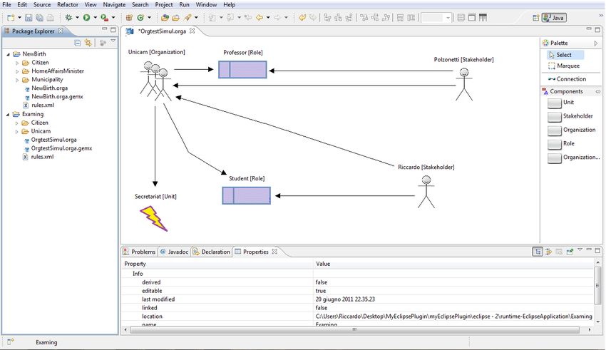
different models and we identify points of interaction among the different model
views. This is in line with general principles of modeling in the e-government
domain [2]. Starting from a Domain Specific Language (DSL) we define in the
past, named eGAML [3]; we propose a practical approach that starting from the
Business Process definition supports domain and IT experts to model and than
simulate specific views in the PA information systems.
    eGAML is based on UML 2.0 and BPMN 2.0 standards and it is encapsulated
in an eclipse plug-in that we developed. Several challenges were faced during the
definition and development of eGAML. The paper illustrates technical solutions
we adopted and eGAML general usage. We provide an overview of tools avail-
able to generate both a graphical editor from the DSL meta-models (such as
GMF, Graphiti, EuGENia and GEMS), and specific editor for BPMN 2.0 (such
as Activiti and jBPM). As a result Eclipse becomes a powerful development
environment for PA related software systems.
    The paper is structured as follows. Section 2 introduces a brief state of the
art review and Section 3 provides an introduction to background technologies.
Section 4 describes the work performed in implementing the eGAML meta-model
and the simulation algorithm. Finally, Section 5 draws some conclusions.

2     State of the art
Several Domain Specific Languages have been developed; most of them are
based over the Zachman framework [4]. In the area of e-government we cite the
PICTURE-method. It consists of a modeling language and related approach,
which guides the application of the language giving a complete overview on
organizations practices focusing on Business Process (BP) [5].
    For what concern the BP simulation and related tools several attempts have
been introduced [6] [7]. Just to cite a few we refer to Protos [8] and ARIS [9] as
important and relevant experiences. In the area of commercial software we cite
Goldsim Pro [10], eClarus Business Process Modeler [11] or ProModel Process
[12]. All of them are mature Business Process Management (BPM) systems with
a more or less structured simulation engine.
    In the most of modelling and simulation approaches (i) relationships between
BP and the other views in the organizations and (ii) domain dependent require-
ments are missed. We try to introduce them and we provide a plan-do-check-act
approach in the design of e-government informative systems.

3     Background
3.1    EMF supporting tools
In order to design and develop the graphical editor based on the EMF meta-
model we compare Graphical Modeling Framework (GMF) [13], Graphiti [14],
EuGENIa [15] and Generic Eclipse Modeling System (GEMS) [16]. Table 1 sum
up the results of our first investigation.
GMF introduces a model-driven approach to generate Eclipse graphical ed-
itors from EMF Ecore files. It is a bridge between EMF and Graphical Editing
Framework (GEF). We withdraw it after several tests. According to our techni-
cal evaluation we realize that developing a good BPMN 2.0 visual editor using
this kind of technology is too complex
Graphiti is an Eclipse-based graphics framework to enable easy development
of state-of-the-art diagram editors for domain models. The main difference be-
tween GMF and Graphiti is that GMF creates a visual editor from EMF file,
instead with Graphiti it is possible to create directly the meta model and than
the visual editor starting from it. Unfortunately, Graphiti does not support EMF
import that in our case is a strict requirement.
EuGENia is a tool that automatically generates the models needed to im-
plement a GMF editor from a single annotated Ecore meta-model. Even if it
introduces an interesting approach it does not reduce developing time respect to
the GMF-based coding, so according to our analysis we realize to skip it.
GEMS tries to bridge the gap between the communities experienced with
visual meta-modeling tools, such as the Generic Modeling Environment, and
those built around the Eclipse modeling technologies, such as the EMF and
the GMF. The framework provides a knowledge base suitable to assert EMF
modeling elements into. Once modeling elements are asserted into the knowledge
base, constraints to relationships between model elements can be add via a easily
edit interface. GEMS is stable and well tested environment.
Table 1. EMF supporting tools: overview
According to our first investigation GEMS results the best option to cre-
ate visual editors bases on customized meta-model. Unfortunately, none of the
investigated tools support our choice to rely on standard BPMN 2.0 EMF meta-
model. We believe that the main reason for that can be the BPMN 2.0 EMF
meta-model incompleteness. In order to solve this issue we decided to relay over
a third part BPMN 2.0 Editor based on EMF as following discussed.3.2 BPMN 2.0 and related modeling tools
Business Process Model and Notation (BPMN) is a graphical representation
for specifying BP in a BP model. The current version is BPMN 2.0 [17]. It
introduces various constructs and two completely new diagram types such as
choreography diagram - modeling of the data exchange between different part-
ners, and conversation diagram - giving an overview of several partners and their
communication links. Although these novelties are very prominent the majority
of the alterations from the past version is the graphic model representation in
the form of a meta-model.
We tested several BPMN 2.0 modelers based on Eclipse (Table 2) but in this
work we focus only on those based on the BPMN 2.0 EMF meta-model [18].
We refer to Activiti [19] and jBoss [20] communities. Activiti Eclispe Plug-in
provides functionalities to design BPMN 2.0 processes and run these processes
on the Activiti Engine. For the implementation of visual editor it uses Graphiti,
and the BPMN 2.0 specification is based on the Eclipse BPMN 2.0 meta-model.
Unfortunately, Activity is not yet complete and it does not provide all BPMN
2.0 elements. Activiti also provides a web-based BPMN2 editor provided by
SIGNAVIO that cover all BPMN2 elements, but it is not Eclipse based and we
faced several integration problems. Also JBoss Community created a BPMN 2.0
Eclipse plug-in named jBPM. As well as Activiti it does not provide all of BPMN
2.0 elements. After some investigations, we have find imeikas jBoss to be our best
choice for modeling BPMN 2.0 processes. According to our investigation it is the
most complete and effective BPMN 2.0 modeling tool.
Table 2. BPMN 2.0 and related modeling tools: overview
4 Modeling and Simulation
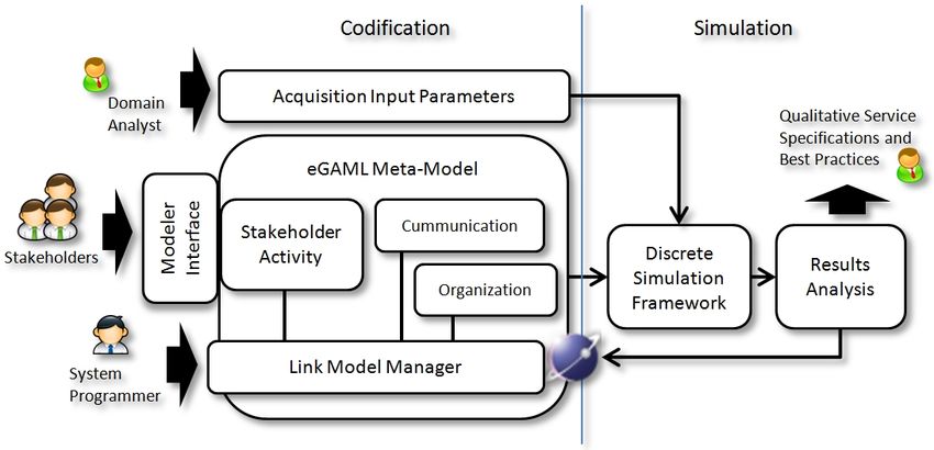
4.1 Architecture Overview
The framework we have defined for BP modelling and simulation is made avail-
able through the development of an Eclipse plug-ins. It permits to have a fully
integrated and user-friendly environment, which support domain experts both
in the BP specification phase (Fig. 1). In particular, the supported meta-models
are created using EMF, while the graphical modeler is supported by GEMS.
Using the resulting plug-in, BP developers can define their models according to
the rules of the eGaml meta-model [3] as following reported.– For each Role in the Organization Model, there is a BPMN 2.0 Model and
a Communication Model that describe its process and communications re-
spectively.
– Each BPMN 2.0 Model is associated to a Communication Model.
– For each Send (Receive) Task in BPMN 2.0 Model there is a Send (Receive)
Task in the Communication Model associated.
Fig. 1. Architecture overview
Rules are stored in a parameterized XML file. The approach can be gener-
alized to add a new meta-model and link it with the others defined by eGaml.
Simulation is also supported by the plug-in according to the algorithm we have
defined. Before launching the simulation BP developers can set different param-
eters such as the number of stakeholders for each role, the average time needed
to complete a task, how much time each stakeholders works, etc. Many statis-
tical functions have been implemented to assess the result of the simulation. It
is also possible to know how many times a stakeholder completes his process,
or how many times a stakeholder complete a specific task. Results of simulation
are shown using histograms created with jFreeChart.
4.2 BPMN2, Organization and Communication Meta-model
For what concern meta-model definition we base our work on BPMN 2.0 meta-
model as already discussed and we introduce Organization and Communication
meta-models.
Organization meta-model permits to describe the structure of an organiza-
tion. This can refer to a PA, group of citizen, schools, etc. The meta-model is
composed by four different elements:
– Organization represents the organization (i.e. University of Camerino, Home
Affairs Minister or Citizen);– Unit represents the different units of the organization (i.e. personnel depart-
ment or Warehouse);
– Role represents the role of Organizations (i.e. secretary and director);
– Stakeholder represents actors of the system as a person or an entity that can
do something (i.e. Mario the director of the unit X).
These elements are related to each others through the following relationships:
– Each Organization is composed by Units;
– For each Organization, there is at least one Role, and each Role can be linked
to at least a single Organization;
– For each Organization, there is at least a Stakeholder, but each Stakeholder
can work in many Organizations;
– Each Stakeholder play at least a Role and each Role has to be played by at
least one Stakeholder.
Fig. 2. Example of Organization Model
Figure 2 shows an example of Organization Model. In this case, there is only
one Organization called Unicam. It has only one Unit, the Secretariat, and it
includes two Roles, the Student and the Professor. Actors of the system are also
two. There is Riccardo that is a Student, and Polzonetti that is a Professor.
Communication meta-models describes how actors interact with each other.
For each Role/Lane it exists a Communication Diagram. Therefore, each actor
has its Communication Model. This meta-model is composed by five different
elements:
– Receive Task means that the actor receives a message from other actors;
– Send Task means that the actor send a message to other actors;– Pool is referring to an organization in the Organization meta-model;
– External Receive Task is a Receive Task of an external actor; it means that
this task is not executed by this actor;
– External Send Task is a Send Task of an external actor; it means that this
actor does not execute this task.
These elements are related to each others through the following relationships:
– Each Pool can be link to zero or more External Send or External Receive
tasks;
– Each External Send or External Receive task can be in only one Pool;
– Each Send Task can be linked to a single External Receive Task and each
External Receive Task can be linked to a single Send Task;
– Each External Send Task can be linked to a single Receive Task and each
Receive Task can be linked to a single External Send Task.
4.3 Business rules as meta-models links
Once all the different meta-models have been defined, we introduce a set of rules
to kink them. The main rules are as following.
– For each Role and for each Receive Task in a Process Model there is only
one Receive Task in a Communication Model with the same Name.
– For each Role and for each Receive Task in a Communication Model there
is only one Receive Task in a Process Model with the same Name.
– For each Role and for each Send Task in a Process Model there is only one
Send Task in a Communication Model with the same Name.
– For each Role and for each Send Task in a Communication Model there is
only one Send Task in a Process Model with the same Name.
– For each Organization in the Organization Model there is at most one Pool
in each Communication Model with the same Name.
– For each Pool in each Communication Model there is an Organization in the
Organization Model with the same Name.
The main element of XML rules file is Rules element. Inside Rules element there
is at least a Rule element. A Rule element is composed by two simple elements.
– Element element: represents the related object and it has two attributes:
• Name: contains name of the related object;
• File: refers to the meta-model where the object can be found (it can be
communication, organization or bpmn2).
– Link element: represents the object that is linked from Element. It has three
attributes:
• Name: contains the name of the linked object;
• File: refers to the meta-model where the object can be found (it can be
communication, organization or bpmn2).• Cardinality: is the cardinality of the relation (i.e. if cardinality is 3, for
each selected object in Element element exactly three linked elements
must exist, or if cardinality is 1..* at least a linked element must exist).
According to the rules, we can deduce the hierarchy of the models. The first
model we need to create is the Organization Model. To do that we implement
functionality that creates automatically the structure of the file system, from an
Organization Model. It creates a folder for each Organization in an Organization
Model and it creates a sub-folder for each role in an Organization with a BPMN2
Model and a Communication Model. There are many advantages in providing
such folder structure. First, we can easily manage authorizations both in edit
and view mode. For example, image that a Manager wants to modify a process
of his stakeholders; in this case, we can easy implement the logic of permits that
avoid the manager to modify something out of his Organization.
4.4 Simulation
To define our simulator we have followed the approach proposed in [6] and tried
to cover all the main aspects described in [21] and in [7]. As matter of fact we use
sub-runs and statistics functions and we did not introduce animation in order
to maintain the framework light.
The approach is based on waterfall steps where the first is the definition of
the problem. Input parameters are following proposed.
– Organization, Process and Communication models are defined according to
the meta-models in eGaml;
– The number of actors there is in the simulation context as well as the Role
they play;
– Information related Actors, like how long an actor work or how much time
an actor spends for doing a specific Task, etc;
– Path priorities as the order of priorities for the routes in case of Gateway
elements.
The outputs parameters we obtain are:
– Number of times that each actor completes his process;
– Time of execution for each actor;
– Number of times that each actor complete a Task;
– Statistical indexes (i.e. average waiting time, trend, variance, standard de-
viation, etc) for each Receive Task.
Figure 3 shows the conceptual model of our simulator. The core of the simu-
lator is the class Simulator; it contains two sets of actors (class Actor). The first
set contains actors with the given inputs parameters (given by user), and the
second set contains actors defined during the simulation process. Every actor
has at least a communication model and a process model (classes Communica-
tion and Process). There are three classes for doing various controls. They areFig. 3. Simulator model class diagram
Errors, Messages and Functions. Errors contains a set of error messages that
are stamped when an error occurs. Messages contains a set of messages that are
printed when something happen. Functions contains a set of generic functions
(i.e. XML reader). Class description is following reported.
– Simulator :
• Messages Information, tracks who send a message, who receive it and
the time of send;
– Actor :
• Time Information, that is the start time, the end time and the execution
time of the actor;
• Task Information, represents the information of Tasks (i.e. the time of
execution of a task);
• Getaway Priority, represents the priorities of Getaway elements;
– Process:
• Process Information, is a simple XML file that describes the process;
– Communication:
• Communication Information, is a simple XML file that describes the
communication.
Based on this conceptual model we have realized the executable tool. There are a
lot of tools created for executing simulation models, but we preferred to develop
it from scratch, creating an algorithm from conceptual model, since available
tools are too dispersed, they are designed for simulating general processes, and
for example in our specific domain they lost some inputs parameters. Besides,
they usually transform the system in a Petri-Net, and after that they do the
simulation based on it.
In our case we define a simulation algorithm based on the concept of actor
time and in a loop cycle that executes a single task for each actor in any time.
For example image that we have the Process model in Figure 4. There are two
different roles, Person and Municipality Worker. Suppose there is a single actor
for each role that works from time 0 to time 100 (where time is a user defined timeFig. 4. Simulation Example
unit), and each Task/Send Task has an execution time equal to 5 (all Receive
Task has a variable time). The algorithm starts executing the firth task of the
first actor. In this case it stats from Persons Send Info. The execution’s time
of Person is now 5, he is waiting in Send Info and in the set of messages there
is a message from Send Info to Receive Info. It is because when a Send Task
is executed the algorithm add a message in the set of messages, contrariwise
when a Receive Task is executed a respective message is erased, if it exists. At
this point algorithm executes a Task of the other actor, Municipality Worker.
The time of Municipality Worker is now set to 5 because the message that he
attends is arrived at 5. Now it’s up to Person. After that Municipality Worker
does Work Task. And it set his time to 10. Now it is Persons time. But he is
still waiting for a message. So the situation does not change. The only action
that we can do is Send Response of Municipality Worker. When algorithm does
Send Response, it adds a new message to the set of the messages and update
the time of Municipality Worker to 15. Finally Receive Response is unlocked at
time 15 and Person can finish his process.
The Simulation results have to be interpreted by an analyst expert through
graphs like histograms or through row textual data. They help us understand
where the system can be improved.
– If the medium waiting time of a Receive Task is higher than the minimum
waiting time, probably there is a block in the process with the respective
Send Task.
– If the distribute indexes are high (i.e. Variance or Standard deviation), or if
the different between the maximum and the minimum waiting time is high,
probably there is a block in the process with the respective Send Task.
– If a stakeholder ends his simulation before (i.e. final stakeholders time is 10
and max stakeholders time is 100), probably there is a slowdown in a linked
processes.– If the medium waiting time of Receive Task is similar to minimum and
maximum waiting time, it means that probably there is not a slowdown in
a linked processes.
– If each actor ends his process for the same times, probably there is not a
slowdown in the system.
5 Conclusion
The paper presents a modeling and simulation framework. We face the modeling
challenge considering standard languages such as UML 2.0 and BPMN 2.0. The
approach is supported by a plug-in for Eclipse platform permitting to have an
integrated environment in which to design and to simulate the information sys-
tem. The plug-in makes easier and more effective the development of software
system in order to provide better services to citizens.
References
1. Schekkerman, J.: How to survive in the jungle of enterprise architecture framework:
Creating or choosing an enterprise architecture framework. Trafford (2006)
2. Becker, J., Algermissen, L., Niehaves, B.: Organizational engineering in public
administrations: a method for process-oriented egovernment projects. In: Proceed-
ings of the 2004 ACM symposium on Applied computing. SAC ’04, New York, NY,
USA, ACM (2004) 1385–1389
3. F.Corradini, Falcioni, D., Polini, A., Polzonetti, A., Re, B.: egaml: A domain
specific language for design and verification of e-government digital services. In:
Proceedings of the IFIP EGOV 2011 conference, Delft (The Netherlands) (2011)
4. Zachman, J.: A framework for information systems architecture. IBM systems
journal 26(3) (2010) 276–292
5. Becker, J., Pfeiffer, D., Räckers, M.: Electronic Government, 6th International
Conference, EGOV 2007, Regensburg, Germany, September 3-7, 2007, Proceedings.
In Wimmer, M., Scholl, H.J., Grönlund, Å., eds.: EGOV. Volume 4656 of Lecture
Notes in Computer Science., Springer (2007)
6. van der Aalst, W., Nakatumba, J., Rozinat, A., Russell, N.: Business process
simulation. Handbook on business process management 1 (2010)
7. Bosilj-Vuksic, V., Ceric, V., Hlupic, V.: Criteria for the evaluation of business
process simulation tools. Interdisciplinary Journal of Information, Knowledge, and
Management 2 (2007) 73–88
8. Verbeek, E., van Hattem, M., Reijers, H., de Munk, W.: Protos 7.0: Simulation
made accessible. Applications and Theory of Petri Nets 2005 (2005) 465–474
9. Scheer, A.: ARIS–business process frameworks. Springer Verlag (1999)
10. Goldsim: (Goldsim modeler) http://www.goldsim.com.
11. eClarus: (eClarus modeler) http://www.eclarus.com.
12. Promodel: (Promodel process simulator) http://www.promodel.com/products/processsimulator/.
13. Eclipse: (Gmf - graphical modeling framework) http://www.eclipse.org/gmf.
14. Eclipse: (Graphiti project) http://www.eclipse.org/graphiti/.
15. Eclipse: (Eugenia) http://www.eclipse.org/gmt/epsilon/doc/eugenia/.
16. White, J., Schmidt, D., Mulligan, S.: The generic eclipse modeling system. In:
Model-Driven Development Tool Implementers Forum, TOOLS. Volume 7. (2007)17. OMG: Business process model and notation (bpmn) 2.0. Technical report, Object
Management Group (2009)
18. Eclipse: (Bpmn 2.0 meta-model) http://www.eclipse.org/modeling/mdt/?project=bpmn2.
19. Activiti: Activiti bpm platform (2010) http://www.activiti.org.
20. jBoss: (jbpm) http://www.jboss.org/jbpm.
21. van der Aalst, W., Nakatumba, J., Rozinat, A., Russell, N.: Business process
simulation: How to get it right. BPM Center Report BPM-08-07, BPMcenter. org
(2008)You can also read