Channel Stabilization with Basic Flow Calculations - Hamilton ...
←
→
Page content transcription
If your browser does not render page correctly, please read the page content below
Channel Stabilization
                                                                    with Basic Flow
                                                                     Calculations

Description   The selection of a channel lining will greatly influence how a drainage channel performs, the
              amount of erosion and scour, the frequency and cost of maintenance, appearance,
              aesthetics, and even safety. In addition, the amount of sediment and nutrients conveyed
              can be influenced greatly by the type of channel lining selected. This BMP examines
              different factors and some basic design parameters for channels and channel linings.
              Suitable applications are any areas which regularly receive and convey concentrated
              stormwater runoff, such as drainage channels, ditches, or swales. Channel linings can also
              be used in areas which occasionally convey stormwater runoff, such as overland relief
              swales or emergency spillways.

Selection     Every drainage channel, ditch, or swale must have some type of channel lining. By default
              and if not specified, then the existing channel lining is native soil or rock. The least
Criteria      expensive and most beneficial lining is usually a grass channel if design parameters do not
              indicate excessive velocities, regular submergence, inadequate flow capacity, or potential
              maintenance problems. Grass channels are easy to maintain, flexible and self-healing,
              attractive in appearance, remove pollutants (see 9.5 Filter Strips and Swales), and decrease
              the amount of runoff by allowing stormwater infiltration and evapotranspiration.
              Grass channels are an example of a flexible lining (may also be called a “soft” or “green”
              lining) which include vegetation as the principal means of preventing erosion. A variety of
              temporary and permanent geosynthetic products can help to establish a soft lining; common
              examples are erosion control matting, excelsior blankets, geogrids filled with soil, or turf
              reinforcement mats. Soft linings are aesthetically pleasing, flexible, and easy to install and
              maintain. Some drawbacks to soft linings are the potential for damage by heavy traffic,
              excessive drought or pollution.
              Riprap and concrete and some geosynthetic channel linings are examples of rigid or “hard”
              linings. These channel linings are used when design velocities exceed permissible values
              for soft linings, or to improve flow capacity by reducing roughness and flow losses.
              Hard linings must be installed in a controlled manner with proper materials, compaction,
              bedding, and anchoring in order to prevent scour, undercutting or settlement.
              By law, anyone who works within or along a stream must obtain an Aquatic Resource
              Alteration Permit (ARAP) from the TDEC Division of Water Pollution Control. The ARAP is
              required for activities such as: dredging, widening a stream channel, straightening a stream
              channel, building a dock or boat ramp, altering a wetland, utility line crossings or streambank
              stabilization.      Visit the TDEC permitting website for more information at
              http://www.state.tn.us/environment/permits/

                          5.2 Channel Stabilization with Basic Flow Calculations
                                              Page 1 of 10
Best Management Practices Manual

                          Related BMPS which impact the selection of channel linings include:
                                 Matting (MA)                         Geotextile (GE)
                                 Diversion Ditch (DI)                  Riprap (RR)
                                 Slope Drain (SD )

Basic Flow                This section contains a description of basic flow computations for use in designing an open
                          channel, ditch or swale. Drainage channels and ditches should generally be designed by a
Calculations              professional engineer to ensure that adequate drainage capacity and allowable flow
                          velocities are provided. Open-channel computations are usually in the form of Manning’s
                          equation:
                                 V = (1.49 / n ) RH2/3 S1/2 , where
                                 V = average velocity in channel (feet per second)
                                 n = Manning’s roughness coefficient (dimensionless)
                                 RH = hydraulic radius of channel = A / W P (expressed in feet)
                                 S = energy grade line = channel slope for uniform flow (dimensionless)
                                 A = cross-sectional flow area (square feet)
                                 WP = wetted perimeter of flow (feet)

                          The total flow through the channel (Q, expressed in cubic feet per second) is
                          equal to the velocity times the cross-sectional flow area: Q = V A

         Figure 1
         Basic Flow Computation – Manning’s Equation

                                         1.21 sq ft area = 0.5 x 1.1 x 2.2                        Given:
                                         2.46 feet WP = (2.22 + 1.12) 0.5
                                                                                         D = 1.10 feet
                                                                       1.82 sq ft area   n = 0.025
                                                                       3.48 feet WP
                                             B = 4 feet
                                                                                         S = 0.01 ft / ft

                                                                                         channel geometry
                                      4.40 sq ft area
              2:1 slope                                                      3:1 slope          Computed:
                                      4.00 feet WP
                                                                                         A = 7.43 sq ft

                                                                                         WP = 9.94 feet

                                                                                         RH = 0.747 feet

                                                                                         V = 4.91 fps

                                                                                         Q = 36.5 cfs

                                     5.2 Channel Stabilization with Basic Flow Calculations
                                                         Page 2 of 10
Chattanooga–Hamilton County Area Water Quality Programs
Manning’s equation is for open-channel flow and assumes a constant uniform flow rate at a
specified slope. There are many factors which can affect this assumption, such as varying
channel widths and slopes, downstream flow restrictions, backwater from dams or other
berms, culvert entrance and exit losses, headwater at culverts or bridges, channel bends,
varying lining materials, etc. Any of these factors will generally require that an experienced
professional engineer be responsible for design and analysis. In addition, channels with
unusual shapes, composite materials or uneven sections will generally require that a
professional engineer with knowledge and experience should be responsible for the design
and analysis. In addition, channels with unusual shapes, composite materials or uneven
sections will generally require that a professional engineer with knowledge and experience
should be responsible for the design and analysis. The major difficulty in estimating velocity
and flow is usually the selection of Manning’s roughness coefficient “n”. Typical values are
listed in Table 1 and Table 2. See Table 3 for n values of grass channels, based upon type
and height of vegetation, and product of velocity (V) and hydraulic radius (RH).
Subcritical and Supercritical Flow
It is useful to know whether a flow is subcritical (also called tranquil flow, backwater flow or
downstream control) or supercritical (also called rapid flow or upstream control). This is
determined by computing the Froude number; a value of FR less than 1 is subcritical and a
value greater than 1 is supercritical. Subcritical flow is greatly preferred because it has a
lower velocity than supercritical flow. A value of FR between 0.8 and 1.2 indicates that the
channel is close to critical flow, and that small changes in channel cross section, flows,
slopes, etc., may cause the water surface to change radically or even create a hydraulic
jump or standing wave. Open channels should not be designed at or near critical flow
conditions.
FR = ( ( Q2 * T) / (g * A3) )1/2 , where
FR = Froude number (dimensionless)
Q = discharge or flow (cubic feet per second)
T = top width of water surface (feet)
g = gravitational constant = 32.2 feet/ second2
A = cross-sectional flow area (square feet)
(for Figure 1) FR = ( (36.52 * 9.5) / (32.2 * 7.433) )0.5 = 0.98
The example channel in Figure 1 is approximately at critical flow and should be changed.
Since subcritical flow is the preferred flow regime, this can be accomplished by widening the
channel, flattening the side slopes, increasing the Manning’s roughness coefficient n, or
decreasing the channel slope.
Critical depth (DC) indicates the flow depth for which the specific energy (E) is at a minimum
value for a given discharge. Specific energy is computed by the equation:
E = D + V2 / (2g) For the example in Figure 1, the specific energy is 1.474 feet.
Using the example in Figure 1, a roughness coefficient value of 0.025 corresponds to any of
several channel linings in Table 1 such as:
— Bare earth, straight and uniform, short grass
— Erosion control matting (excelsior mat)
— Rocky channel, smooth and very uniform
5.2 Channel Stabilization with Basic Flow Calculations
Page 3 of 10Best Management Practices Manual
Using same geometry as shown in Figure 1 with a grass channel lining instead will yield the
following two sets of answers for the same given flow of 36.5 cfs. In general, a conservative
design will use unmowed grass to check conveyance and mowed grass to check for
velocities. So the design depth would be 2.06 feet and the design velocity would be 3.56
fps.
Table 1
Manning’s Roughness Coefficient – Channels
Closed Conduits n
Brick 0.016
Cast-iron pipe 0.013
Cemented rubble 0.021
Concrete pipe 0.013
Corrugated metal pipe, plain, regular corrugations 0.024
Corrugated metal pipe, asphalt-paved invert, flowing full 0.020
Closed Conduits n
Corrugated metal pipe, asphalt-paved, 50% flow depth 0.015
Corrugate metal pipe, large corrugations (1” or 2” deep) 0.030
Plastic pipe, smooth/corrugated (consult manufacturer) ------
PVC pipe 0.011
Steel pipe 0.010
Vitrified clay 0.013
Open Channels n
Asphalt pavement 0.016
Bare earth, straight and uniform, no vegetation 0.020
Bare earth, straight and uniform, with some short grass 0.025
Bare earth, winding and sluggish 0.025
Bare earth, winding and sluggish, with some short grass 0.030
Brick 0.015
Cemented rubble 0.020
Concrete channel, unfinished 0.015
Concrete channel, troweled 0.013
Concrete channel, troweled with exposed gravel finish 0.017
Concrete channel with mortared or riprap sides 0.015 - 0.030
Concrete gutter, finished and troweled 0.013
Erosion control matting (excelsior mat or straw netting) 0.025 - 0.035
Erosion control matting (jute net) 0.022
Grass Table 3
Gravel or aggregate, compacted 0.030 - 0.050
Gravel bottom, with weeds on banks 0.035
Riprap, dumped (n chosen from D50 size) See 5.8 Riprap
Riprap, grouted and placed as a smooth uniform channel 0.030 - 0.040
Rocky channel, smooth and uniform 0.025 - 0.035
Rocky channel, irregular and winding 0.040 - 0.050
Weeds and brush, uncut, only on banks 0.040 - 0.080
Weeds and brush, uncut, across entire channel 0.080 - 0.120
5.2 Channel Stabilization with Basic Flow Calculations
Page 4 of 10Chattanooga–Hamilton County Area Water Quality Programs
Grass channels are frequently grouped into categories based upon the “retardance”
that reflects the height and type of vegetation, flow characteristics of channel, etc.
The retardance classification taken from Table 3 is then used in Figure 2 to select a
Manning’s roughness coeffficient based upon the product of velocity, V, and the
hydraulic radius, RH. Solving Manning’s equation for a grass surface, due to the
variable roughness coefficient, is an iterative process for which a spreadsheet may
be helpful.
Table 2
Manning’s Roughness Coefficient – Natural Channels Closed Conduits
Natural Stream (less than 100 feet wide at flood stage) n
Clean, straight, no rifts or deep pools, grass banks* 0.025 - 0.035
Clean, straight, grass with some stones and weeds* 0.030 - 0.040
Clean, winding, pools and shoals* 0.033 - 0.045
Clean, winding, pools and shoals, some stones and weeds* 0.035 - 0.050
* Values may be increased by the largest of the 4 possible adjustments below:
1. Adjust upward by 0.005 for lower stages or ineffective flow areas
2. Adjust upward by 0.005 for larger stone and weeds
3. Adjust upward by 0.010 to 0.020 for partially submerged trees / branches
4. Adjust upward by 0.030 to 0.050 for entire submerged trees in channel
Sluggish reaches, deep pools, many weeds 0.050 - 0.080
Sluggish, many deep pools, full of weeds, heavy timber 0.075 - 0.150
Mountain stream, gravel and cobbles, with steep banks 0.030 - 0.050
Mountain stream, cobbles and boulders, with steep banks 0.040 - 0.070
• In general, n values are lower for larger streams because the banks offer less resistance. Usually
larger streams have been modeled by government agencies such as TVA, FEMA, or the City of
Chattanooga so that some guidance is available on roughness coefficients used.
• Manning’s n values can be substantially different during summer when vegetation may be overgrown
and trees contain branches full of leaves. Adjust values upward if stream flow submerges trees and
tree branches.
Floodplains (adjacent to natural streams) n
Cleared land with tree stumps 0.040 - 0.050
Pasture, no brush, short grass 0.030 - 0.035
Pasture, no brush, high grass 0.035 - 0.050
Farmland, no crops 0.030 - 0.040
Farmland, mature crops 0.040 - 0.050
Heavy weeds, scattered brush 0.050 - 0.070
Light brush and trees 0.050 - 0.080
Medium to dense brush 0.070 - 0.110
Dense brush, thick trees, undergrowth, fallen logs 0.100 - 0.160
5.2 Channel Stabilization with Basic Flow Calculations
Page 5 of 10Best Management Practices Manual
Natural streams have constantly varying cross sections and slopes, so that the Manning’s
equation should be used carefully with the understanding that other factors may affect flow
depth. Therefore, the use of Manning’s equation for natural streams should only be for
rough estimating purposes.
Water surface profile programs (such as HEC-2 and HEC-RAS developed by the US Army
Corps of Engineers Hydraulic Engineering Center and WSPRO) can handle multiple
roughness coefficients, complex geometry, bridges, culverts, flow obstructions, and varied
flow values into consideration. Water surface profiles must be prepared by a professional
engineer using the best available data.
Table 3
Retardance Classifications for Grass Channels
Class Type of Vegetation Condition
Yellow bluestem ischaemum Excellent stand, tall, 36” average
A Weeping lovegrass Excellent stand, tall, 30” average
Alfalfa Good stand, uncut, 11”
Bermudagrass Good stand, tall, 12”
Blue gamma Good stand, uncut, 13”
Kudzu Very dense growth, uncut
B Reed canarygrass Good stand, cut, 12” to 15”
Sericea lespedeza Good stand, not woody, tall, 19”
Tall fescue Good stand, uncut, 18”
Weeping lovegrass Good stand, uncut, 13”
Grass mixture #1 Good stand, uncut
Grass mixture #2 Good stand, uncut, 20”
Bahiagrass Good stand, uncut, 6” to 8”
Bermudagrass Good stand, cut, 6” to 8”
Centipedegrass Very dense cover, 6” to 8”
C Crabgrass Fair stand, uncut, 10” and longer
Kentucky bluegrass Good stand, headed, 8” to 10”
Redtop Good stand, uncut, 15” to 20”
Tall fescue Good stand, cut or uncut, 6” to 8”
Grass mixture #3 Good stand, uncut, 6” to 8”
Bahiagrass Good stand, cut, 3” to 4”
D Bermudagrass Good stand, cut, 2.5”
Buffalograss Good stand, uncut, 3” to 6”
Centipedegrass Good stand, cut, 3” to 4”
Kentucky bluegrass Good stand, cut, 3” to 4”
Red fescue Good stand, uncut, 12”
Sericea lespedeza Good stand, cut, 2”
Tall fescue Good stand, cut, 3” to 4”
Grass mixture #4 Good stand, uncut, 4” to 5”
E Bermudagrass Good stand, cut, 1.5”
Any type of grass Burned or trampled, any length
Native grass mixture #1 - prairie grasses, bluestem, blue gamma
Summer grass mixture #2 - tall fescue, red fescue, sericea lespedeza
Summer grass mixture #3 - timothygrass, smooth bromegrass or orchardgrass
Spring/autumn grass mixture #4 - orchardgrass, redtop, annual lespedeza
5.2 Channel Stabilization with Basic Flow Calculations
Page 6 of 10Chattanooga–Hamilton County Area Water Quality Programs
Grass channels are often designed as a parabolic shape without any corners or slope
breaks. The following formulas for cross-sectional flow area (A) and hydraulic radius (RH)
are based on the top width of flow (T) and maximum flow depth at the center of channel (D):
A = 2/3 (T D)
RH = ( T2 D) / (1.5 T2 + 4 D2)
UNMOWED MOWED
Retardance B: Retardance D:
Q = 36.5 cfs Q = 36.5 cfs
n = 0.089 n = 0.039
D = 2.06 feet D = 1.38 feet
A = 18.85 sq ft A = 10.28 sq ft
WP = 15.12 feet WP = 11.45 feet
RH = 1.247 feet RH = 0.898 feet
V = 1.94 fps V = 3.56 fps
Figure 2
Manning’s Roughness Coefficient – Grass Channels
0.50
0.40
0.30
0.20
A
0.15
B
0.10
0.08 C
D
0.05
0.04 E
0.03
0.02
0.1 0.2 0.4 0.7 1 1.5 2 3 4 7 10 15 20
V RH (product of velocity and hydraulic radius)
5.2 Channel Stabilization with Basic Flow Calculations
Page 7 of 10Best Management Practices Manual
A channel lining may be judged adequate or permissible based on two possible
criteria, either permissible shear stress or permissible velocity. Permissible shear
stress is based on the force necessary to displace or move the soil, aggregate, or other
type of channel lining. The formula for normal shear stress (T) at the bottom of a
uniform channel is shown below. This value is adjusted for several factors such as
side slope, bend angles, shape of channel, etc., before being compared to published
values of permissible shear stress.
T = γ D S
T = shear stress (pounds per square foot)
γ = unit weight of water (62.4 pounds per cubic foot)
D = flow depth of water (feet)
S = channel slope (feet per foot)
The simpler design method is to specify a permissible velocity for each type of channel
lining. Typical permissible velocities are listed in Table 4. In general, a temporary
channel lining should be considered if the design flow velocity for bare soil is greater
than 2 feet per second. For preliminary design, a soil may be considered erodible if it
has a published K value of 0.35 or greater in the Hamilton County soils map.
Table 4
Permissible Velocities
Permissible
Channel Lining Material
Velocity (fps)
Silt or very fine-grained materials 1.5
Fine sand, sandy loam, silty loam 2.0
Undisturbed alluvial sediments 3.5
Stiff clay 3.5
Coarse sand or fine gravel (no silt) 4.0
Coarse gravel 5.0
Cobbles, hard pan, shale 5.5
0- 5% 5 -10% >10%
Erodible Soil (silt, loam, sand)
Bermuda grass 5.5 4.5 3.5
Bahia grass, Blue Gamma, Kentucky bluegrass Reed canary grass, Tall fescue 4.5 3.5 2.5
Mixture (fescue, lespedeza., legumes) 3.5 3.0 ----
Alfalfa, Crabgrass, Kudzu, Sericea lespedeza Weeping love grass, Yellow
3.0 2.5 ----
bluestem
Resistant Soil (gravel, clay, cohesive)
Bermuda grass 6.5 5.5 4.5
Bahia grass, Blue Gamma, Kentucky bluegrass Reed canarygrass, Tall fescue 5.5 4.5 3.5
Mixture (fescue, lespedeza., legumes) 4.5 3.5 ----
Alfalfa, Crabgrass, Kudzu, Sericea lespedeza Weeping love grass, Yellow
3.5 3.0 ----
bluestem
5.2 Channel Stabilization with Basic Flow Calculations
Page 8 of 10Chattanooga–Hamilton County Area Water Quality Programs
Maintenance Channel linings should be inspected at least weekly during the construction phases to
ensure proper functioning and necessary control of erosion and sediment. Inspect channels
monthly during the first year after construction to verify that drainage channels work properly
as designed and constructed.
After the first year, channel linings should be inspected at least quarterly on a permanent
basis. Look for erosion, siltation, undercutting or settlement throughout the length of
channel. Verify that upstream and downstream portions of channel are not adversely
affected.
Limitations Flexible channel linings need frequent maintenance and inspections to ensure adequate
function and erosion control. Soft channel linings can be damaged or stressed due to many
factors.
Rigid permanent channel linings often result in prevention of habitat establishment. Hard
linings may be damaged due to settlement, scour or undercutting despite the best efforts
and care taken during installation.
Inadequate coverage or depth of channel linings will result in erosion, washout, and poor
plant establishment. If the channel grade and liner are not appropriate for the amount of
runoff, channel bottom erosion may result.
Riprap must be sized correctly and installed according to correct procedures. If the channel
slope is too steep or riprap is too small, displacement may occur. Displaced riprap may
obstruct channel or cause additional damage (see Section 5.8 Riprap).
References California Department of Transportation. 1997. Caltrans Highway Design Manual.
Charlotte (City of), and Mecklenburg County. July 1993. Charlotte Mecklenburg Storm Water
Design Manual.
Georgia State Soil and Water Conservation Commission (SSWCC). 1999. Manual for
Erosion and Sediment Control in Georgia. Fifth Edition.
Kentucky Transportation Cabinet. January 1994. Drainage Guidance Manual.
North Carolina Sediment Control Commission. September 1988. Erosion and Sediment
Control Planning and Design Manual.
Smoot, James and Russell Smith. December 1999. Soil Erosion Prevention & Sediment
Control. University of Tennessee, Department of Civil & Environmental Engineering.
United States Bureau of Public Roads. August 1961. Design Charts for Open-Channel Flow,
Hydraulic Design Series No. 3.
United States Bureau of Public Roads. May 1965. Design of Roadside Drainage Channels,
Hydraulic Design Series No. 4.
University of Tennessee Department of Civil and Environmental Engineering. August 1998.
Soil Erosion Prevention and Sediment Control - Reducing Nonpoint Source Water Pollution
on Construction Sites.
Virginia, Department of Conservation and Recreation, Division of Soil and Water
Conservation. 1992. Virginia Erosion and Sedimentation Control Handbook, Third Edition.
5.2 Channel Stabilization with Basic Flow Calculations
Page 9 of 10Best Management Practices Manual
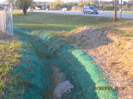
Photos 1 - 2
An Application of ‘Soft’ or ‘Green’ Channel Lining
5.2 Channel Stabilization with Basic Flow Calculations
Page 10 of 10You can also read