A Hybrid Optimization Algorithm for Low RCS Antenna Design

Page created by Salvador Thornton
 
CONTINUE READING
A Hybrid Optimization Algorithm for Low RCS Antenna Design
RADIOENGINEERING, VOL. 21, NO. 4, DECEMBER 2012                                                                         1007

                         A Hybrid Optimization Algorithm
                           for Low RCS Antenna Design
                                                Wei SHAO, Xinyue ZHU

   School of Physical Electronics, University of Electronic Science and Technology of China, 610054 Chengdu, China

                                     weishao@uestc.edu.cn, zhuxinyue888@163.com

Abstract. In this article, a simple and efficient method is     antennas. Due to the basic radiation requirement of patch
presented to design low radar cross section (RCS) patch         antennas, the shaping method becomes one of the most
antennas. This method consists of a hybrid optimization         effective methods for the antenna RCS reduction. In [8],
algorithm, which combines a genetic algorithm (GA) with         circle and rectangular slots on the antenna patch are intro-
tabu search algorithm (TSA), and electromagnetic field          duced to cut off surface currents of high-order modes.
solver. The TSA, embedded into the GA frame, defines the        Techniques of ground-cut slots are applied to the design of
acceptable neighborhood region of parameters and                a patch antenna which achieves the RCS reduction [9]. [10]
screens out the poor-scoring individuals. Thus, the repeats     introduces some types of fractal slots on an antenna patch
of search are avoided and the amount of time-consuming          to obtain the low backscattering. Frequency selective sur-
electromagnetic simulations is largely reduced. Moreover,       face (FSS) structures are also presented to reduce RCS of
the whole design procedure is auto-controlled by program-       reflect-array antennas [11].
ming the VBScript language. A slot patch antenna example
                                                                     In general, a low RCS antenna is difficult to design
is provided to verify the accuracy and efficiency of the
                                                                due to the simultaneous consideration on antenna radiation
proposed method.
                                                                and scattering. This design often relies on an optimization
                                                                procedure with a number of EM simulations, which are
                                                                very time consuming. [12] uses a differential evolution
Keywords                                                        algorithm (DEA) to optimize geometric parameters of
                                                                a low RCS antenna. Based on the separate DEA for the
     Genetic algorithm, RCS, slot antenna, tabu search          radiation and scattering modules, the individuals of bad
     algorithm.                                                 radiation performance avoid the unnecessary RCS simula-
                                                                tion of the method of moment (MoM). However, the fit-
                                                                ness calculations for each generation involve both of the
1. Introduction                                                 radiation and scattering factors, which maybe lead to
                                                                an inefficient solution. In [13], combined with the high fre-
      An antenna is often a main contributor to the overall     quency simulation software (HFSS), a genetic algorithm
radar cross section (RCS) of an aircraft platform. The          (GA) is proposed to design two low RCS slot antennas.
antenna RCS reduction has been a hot topic for the current      Some strategies, such as separation of radiation and scatter-
stealth technologies in electromagnetic (EM) engineering        ing models, elitist selection and two-point crossover, are
[1]-[2].                                                        used to speed up the convergence of the GA.
      In the past few decades, patch antennas have been               Although the GA is robust and widely used in EM
widely used due to their conformability and simplicity of       optimization, it needs to call the time-consuming EM
design. By creating a resonance with an appropriate load        simulation solver hundreds of times to converge to a global
impedance, the RCS of a patch antenna can be substantially      extremum. Therefore, how to reduce the amount of calls of
reduced at a specific frequency [3]-[4]. For a circular patch   the EM solver is a key issue to improve the optimization
antenna, scattering and radiation responses are tuned by        efficiency. To possess quicker convergence and obtain
controlling the bias voltage across a varactor diode to re-     global optimum in the most probability, a tabu search algo-
duce the antenna RCS at some threat frequencies [5]. The        rithm (TSA) is embedded into GA for multilayer optical
RCS of a rectangular patch antenna in a lossy substrate-        coating optimization and yard cranes scheduling [14]-[15].
superstrate configuration is reduced at the cost of lowering    The TSA, as a local search procedure, is a very efficient
the radiation efficiency [6]. The RCS peaks of a patch          optimization algorithm whose tabu list avoids the repeats
antenna printed on a ferrite substrate can be shifted by        of search. In this article, more exact optimized solutions
changing the magnetic bias field [7].                           can be obtained through controlling the searching
     Above methods for RCS reduction of patch antennas          neighborhood region from the parameter sweeping. For the
are at the cost of worsening the gain and bandwidth of the      proposed hybrid algorithm, the GA is applied as the main
A Hybrid Optimization Algorithm for Low RCS Antenna Design
1008                                        W. SHAO, X. ZHU, A HYBRID OPTIMIZATION ALGORITHM FOR LOW RCS ANTENNA DESIGN

frame due to its global ability and the improved TSA is            information, which has important effect on the radiation
embedded into the GA to overcome the disadvantages of              performance of antennas, is evaluated by the tabu list. Each
slow convergency of GA.                                            individual gets a score determined by a criterion to judge
                                                                   its quality. If the score is low, which means that this indi-
                                                                   vidual is not similar to the feature of bad individuals, it will
2. Hybrid Optimization Algorithm                                   be sent to HFSS simulation. If the score is high, parameters
                                                                   of the individual incorporate more bad features and it will
      Presently, GA has been widely applied to the optimi-         not take time in conducting the simulation in HFSS for it.
zation of various EM problems [16]. It has a particular
                                                                         In the classical TSA, the search progresses by itera-
parallel mechanism that guarantees the diversity of solution
                                                                   tively moving from the current solution to an improved
to a certain degree. But its converging speed will become
                                                                   solution in the neighborhood. Instead, the proposed TSA
slow when the solution approaches the optimum. For our
                                                                   mainly aims at picking out the individuals with unaccept-
proposed hybrid algorithm, GA is applied as the main
                                                                   able radiation performances, which will not be sent to be
frame because the global information can be clearly re-
                                                                   simulated in HFSS. The tabu list with the effect of parame-
flected with the strong ability of general search. A simpli-
                                                                   ters is established by pre-determination from parameter
fied TSA is embedded in GA to overcome the disadvan-
                                                                   sweeping in HFSS. Through the use of the memory struc-
tages of GA. For the low RCS patch antenna design, the
                                                                   ture, the amount of time-consuming simulations will be
flowchart which consists of the optimization module and
                                                                   largely reduced. The score for each individual is given by
simulation module is shown in Fig. 1. The optimization
module obtains optimized individuals of next generation                          Score   ai | xi  Ti |, i  1, 2, 3,...      (1)
and controls HFSS with VBScript. With the VBScript,                                         i

HFSS returns its results to the optimization algorithm for         where ai is the empirical scale factor which stands for the
calculating the fitnesses after finishing a simulation of the      influence of an optimized parameter, xi is the optimized
present generation. The two processes are being run alter-         parameter, and Ti is the corresponding threshold value that
nately until the program is terminated or an optimal solu-         determines an acceptable neighborhood of each solution in
tion is got.                                                       | xi  Ti | , where |  | is a norm.

                                                                   2.2 Optimization for Low RCS Antennas
                                                                        The initialized population in Fig. 1 is made up of the
                                                                   randomly created chromosomes. Each chromosome coded
                                                                   by a binary number represents an individual prototype of
                                                                   an antenna structure. In the binary coding, the parameters xi
                                                                   are each represented by a finite length binary string. The
                                                                   combination of all the encoded parameters is a string of
                                                                   ones and zeros.
                                                                         Firstly, each individual in a new population generated
                                                                   by the GA will be evaluated by the tabu list. If the score is
                                                                   higher than a given value, which means the individual in a
                                                                   poor-scoring area, its fitness value is set to a large number
                                                                   a and it will not be sent to HFSS with simulation. The
                                                                   acceptable individuals with small scores will be sent to be
                                                                   simulated in HFSS through the VBScript. Secondly, ac-
                                                                   cording to their geometry parameters, the antenna radiation
       Fig. 1. Flowchart for the low RCS antenna design.
                                                                   models are established and calculated in HFSS. Thirdly, if
                                                                   the individuals meet the radiation requirements, such as S11
2.1 A Simplified TSA                                               and gain conditions, their corresponding scattering models
                                                                   are established and fitness values are calculated. Other-
       TSA enhances the search performance by using a tabu         wise, the fitness value is set to the large number a and the
list that describes the visited solutions or user-provided sets    scattering simulation is skipped. Thus, a waste of time to
of rules. If a potential solution has been previously visited      simulate scattering models of the worse individuals is
within a certain short-term period or if it has violated           avoided. Last, the fitness of each individual of the current
a rule, the algorithm does not consider its possibility re-        generation is transferred to GA and the parameters of indi-
peatedly. The most important feature of the simplified TSA         vidual are optimized to produce a new population. The
in this article is to prevent the revisiting of local minima in    fitness function is defined as follows:
the parameter space. The tabu list is adopted to depict the                                     N
                                                                                                     1   M
                                                                                                                            
features of acceptable individuals and judge the candidates                          fitness           A     RCS( i )      (2)
to be simulated or not for the next step. Some parameter                                       j 1  M   i 1              
A Hybrid Optimization Algorithm for Low RCS Antenna Design
RADIOENGINEERING, VOL. 21, NO. 4, DECEMBER 2012                                                                                                                 1009

where M is the number of the RCS sample point versus              the slope of each curve, and Ti is appropriately the value
frequencies, ARCS is the RCS value of an individual               corresponding to 2.2 GHz for each curve, respectively. For
antenna, and N represents for the different incident angles.      example, the value of 12 mm can be extract from the inter-
                                                                  section of the dot line and circle line, which stands for the
      According to the results of fitness evaluation, indi-
                                                                  threshold value of lP1. Because the slope of lP3 curve is
viduals are selected by the proportionate selection strategy.
                                                                  larger than those of lP1 and lP2, the empirical scale factor a
The selected individuals act as parents for a two-point
                                                                  corresponding to lP3 is chosen larger than the two others.
crossover to rearrange the genes for producing better com-
                                                                  Similarly, ai and Ti corresponding to the locations Pi of the
binations of genes. Therefore, a new generation will have
                                                                  patch slot can be obtained through the parameter sweeping.
more fit individuals than the former one. In order to speed
                                                                  Thus, a tabu list can be established from Fig. 3, as shown
up the convergence of GA, a certain amount of best indi-
                                                                  in Tab. 1. Here, only the positions and lengths of patch
viduals are saved and inserted into the new generation
                                                                  slots are involved because the effect of ground slots on
directly in the elitist strategy. Moreover, the TSA reduces
                                                                  radiation performance is relatively weak. Through the use
the consuming time of EM simulations, too. In order to
                                                                  of tabu list, about one fifth of the individuals in a popula-
avoid sticking at local optima, the mutation occurs with
                                                                  tion avoid the unnecessary radiation simulation in HFSS in
a low probability, of a value of 0.01 in this article. After
                                                                  this design.
the GA produces a new generation, the individuals in the
new population are evaluated by the tabu list and sent to
                                                                                                   2.7
HFSS for simulation again. The simulation and optimiza-
tion are run alternatively until the termination condition is                                      2.6
                                                                                                                        lp1

                                                                         Resonant frequency(GHz)
satisfied.                                                                                         2.5
                                                                                                                        lp2
                                                                                                   2.4                  lp3

3. A Low RCS Slot Antenna Example                                                                  2.3

                                                                                                   2.2
      As an example, a slot patch antenna, shown in Fig. 2,
is studied. The substrate is 2 mm thick RT5880 with a                                              2.1            Operating frequency
relative permittivity of 2.2. The coaxial feed probe is                                            2.0
3.3 mm beneath the center of the patch. The width of each                                                5    6     7     8 9 10 11 12 13 14 15 16
                                                                                                                         Length of patch slot (mm)
rectangular slot on the patch and ground is 2 mm. The
parameters to be optimized are the slot location Pi (i=1, 2,           Fig. 3. Parameter sweeping for the lengths of patch slots.
3) on patch and Gj (j=1, 2, 3, 4) on ground, and slot length
lPi (i=1, 2, 3) and lGj (j=1, 2, 3, 4). A rectangular patch                                             P1                 P2          P3       lP1      lP2   lP3
                                                                       a                                1                 2.5           2        3        3     5
antenna without slots is used as a reference antenna, with
                                                                     T(mm)                           (-10,-3)            (-5,3)      (7,2.5)    12       11    15
a patch of 41.6×32 mm2 on a ground of 80×70 mm2.
                                                                       Tab. 1. Information of the tabu list.

                                                                       A population incorporates 40 individuals and the ma-
                                                                  ximal iteration of generation is 10. The acceptable radia-
                                                                  tion performance is set as S11 < -15 dB and gain > 7dB,
                                                                  respectively. Besides, the best 10% individuals of
                                                                  population have been considered as the elitists. The
                                                                  optimization results are listed in Tab. 2.
                                                                                                                                Patch slots
                                                                                                                              Location (x, y)          lP
                                                                                                         P1                    (-10.4,-0.65)          14.3
                                                                                                         P2                      (-2.9,2.85)          10.5
                                                                                                         P3                       (8.6, 1.6)          16.8
                                                                                                                              Ground slots
                                                                                                                              Location (x, y)          lG
                                                                                                     G1                         (17.6, 16.7)          14.8
                                                                                                     G2                       (24.2, -16.15)          16.9
     Fig. 2. Geometric structure of the optimized slot antenna.                                      G3                       (-27.6, 14.35)          14.3
                                                                                                     G4                         (-27.8, -17)          13.4
     Sweeping each optimized parameter in HFSS before
                                                                       Tab. 2. Geometry of the optimized slot antenna (unit: mm)
the whole optimization process is needed to determine ai
and Ti in (1). As mentioned above, the tabu list is obtained            Fig. 4 shows the convergence for RCS reduction of
with the radiation requirement, and the operating frequency       the hybrid GA, non-elitist GA and elitist GA programs,
of 2.2 GHz is considered here. Taking the length lPi of the       which consist of the minimum values of average RCS of
three patch slots for example, Fig. 3 plots the results of        different incident angles for each generation. From Fig. 4,
parameter sweeping. So, ai is appropriately determined by         the convergency speed of the hybrid GA, which involves
A Hybrid Optimization Algorithm for Low RCS Antenna Design
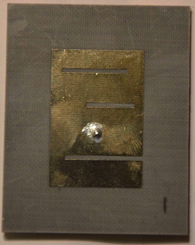
1010                                                                           W. SHAO, X. ZHU, A HYBRID OPTIMIZATION ALGORITHM FOR LOW RCS ANTENNA DESIGN

the parameter sweeping in HFSS before optimization proc-                                                      The photographs of the reference and slot antennas
ess, is higher than that of the Non-elitist GA and elitist GA.                                           are shown in Fig. 5. Fig. 6 depicts the simulated and meas-
                                                                                                         ured return losses of the two antennas. Both their resonant
                                            -20
                                                                                                         frequencies are about 2.17 GHz. The simulated xoz-plane
    Average RCS of incident angles (dBsm)

                                            -22
                                                                                                         and yoz-plane radiation patterns of the antennas at
                                                                       Elitist GA                        2.17 GHz are shown in Fig. 7. The slot antenna has normal
                                            -24                        Non-elitist GA                    radiation performance compared with that of the reference
                                                                       Hybrid GA                         antenna.
                                            -26

                                                                                                                         0
                                            -28

                                            -30                                                                          -5

                                            -32                                                                         -10
                                                  0   2       4        6          8         10

                                                                                                              S11(dB)
                                                           Generation number
                                                                                                                        -15
                    Fig. 4. Convergence for RCS reduction of three GAs.                                                                                      Ref. antenna (simulated)
                                                                                                                        -20                                  Slot antenna (simulated)
     Tab. 3 shows the calculation time of the three GAs.                                                                                                     Ref. antenna (measured)
                                                                                                                                                             Slot antenna (measured)
Because the simulation time in HFSS is much more than
                                                                                                                        -25
the GA operation time in Matlab, only the CPU time of                                                                      1.0         1.5     2.0     2.5          3.0        3.5      4.0
HFSS simulation is given in Tab. 3. All calculations are                                                                                        Frequency (GHz)
performed on an AMD X6 2.8-GHz and 4G RAM ma-
                                                                                                              Fig. 6. S11 of the reference and slot antennas.
chine. Although more CPU time is required for parameter
sweeping in the hybrid GA, more than 20% of individuals                                                                                                0
in a population are not sent to HFSS for radiation simula-                                                                       10           330                   30

tion with the tabu list, which leads to an efficient solution.                                                                    5
                                                                                                                                  0
                                                                                                                                       300                                60
                                                                                                                                  -5
                                                          Elitist GA       Non-elitist GA    Hybrid GA                           -10
  Parameter sweeping                                          ---               ---             4617                             -15
  Radiation simulation                                      27640             28462            21376                             -20 270                                        90
                                                                                                                                 -15
  Scattering simulation                                     16552             17068            11945                             -10
       Total time                                           44192             45530            37938                              -5                  Ref. antenna
                                                                                                                                       240                                120
                                                                                                                                  0                   Slot antenna
                    Tab. 3. Calculation time for three GAs (unit: sec).                                                           5
                                                                                                                                 10           210                   150
                                                                                                                                                      180

                                                                                                                                                (a) xoz-plane

                                                                                                                                                       0
                                                                                                                                  10          330                   30
                                                                                                                                   5
                                                                                                                                   0
                                                                                                                                  -5    300                               60
                                                                                                                                 -10
                                                                                                                                 -15
                                                                                                                                 -20
                                                                                                                                 -25
                                                                                                                                     270                                       90
                                                                                                                                 -25
                                                                                                                                 -20
                                                                                                                                 -15
                                                          (a) Reference antenna                                                  -10
                                                                                                                                  -5    240          Ref. antenna         120
                                                                                                                                   0                 Slot antenna
                                                                                                                                   5
                                                                                                                                  10          210                   150
                                                                                                                                                      180

                                                                                                                                                (b) yoz-plane
                                                                                                              Fig. 7. Simulated radiation patterns of the reference and slot
                                                                                                                      antennas at 2.17 GHz.

                                                                                                              The comparisons of simulated RCS versus frequency
                                                                                                         between the slot and reference antennas for different inci-
                                                                                                         dent angles are shown in Fig. 8. The incident plane wave is
                                                                                                         with the θ polarization. As shown in Fig. 8, the monostatic
                                                                                                         RCS of the optimized slot antenna is reduced in the fre-
                                                            (b) Slot antenna                             quency range of 2-8 GHz compared to that of the reference
                    Fig. 5. Photographs of the antennas with top and back views.                         antenna.
RADIOENGINEERING, VOL. 21, NO. 4, DECEMBER 2012                                                                                                      1011

                    -15

                    -20
                                                                                  Acknowledgements
                    -25
                                                                                       This work was supported in part by the NCET Foun-
                    -30
                                                                                  dation (11-0065), the Natural Science Foundation of China
       RCS (dBsm)

                    -35
                                                                                  (60901023) and the Fundamental Research Funds for the
                    -40                                                           Central Universities (ZYGX2010J043).
                    -45

                    -50                     Ref. antenna
                                            Slot antenna
                    -55
                             2       3        4       5       6           7   8   References
                                             Frequency (GHz)

                                 (a) Incident angle (  60o ,  0o )              [1] GONZALEZ, C. G., LOPEZ, Y. A., CASAS, A. D., ANDRES, F.
                                                                                        L.-H. Characterization of antenna interaction with scatterers by
                       -15                                                              means of equivalent currents. Progress in Electromagnetics
                                                                                        Research, 2011, vol. 116, p. 185 - 202.
                       -20
                                                                                    [2] XU, H.-Y., ZHANG, H., Lu, K., ZENG, X.-F. A holly-leaf-shaped
                       -25                                                              monopole antenna with low RCS for UWB application. Progress
                                                                                        in Electromagnetics Research, 2011, vol. 117, p. 35 - 50.
          RCS (dBsm)

                       -30
                                                                                    [3] POZAR, D. M. Radiation and scattering from a microstrip patch
                       -35
                                                                                        on a uniaxial substrate. IEEE Transactions on Antennas and
                                                                                        Propagation, 1987, vol. 35, no. 6, p. 613 - 621.
                       -40                                Ref. antenna
                                                          Slot antenna
                                                                                    [4] VOLAKIS, J. L., ALEXANIAN, A., LIN, J. M. Broadband RCS
                       -45
                                                                                        reduction of rectangular patch by using distributed loading.
                             2       3        4       5       6          7    8         Electronic Letters, 1992, vol. 28, no.25, p. 2322 - 2325.
                                              Frequency (GHz)
                                                                                    [5] ABERLE, J. T., CHU M., BIRTCHER, C. R. Scattering and
                                 (b) Incident angle (  60o ,  45o )                 radiation properties of varactor-tuned microstrip antennas. 1992
                                                                                        PIEEE AP-S International Symposium, 1992, p. 2229 - 2232.
                       -10
                                                                                    [6] JACKSON, D. R. The RCS of a rectangular microstrip patch in
                                                                                        a substrate-superstrate geometry. IEEE Transactions on Antennas
                       -20                                                              and Propagation, 1990, vol. 38, no. 1, p. 2 - 8.

                       -30                                                          [7] POZAR, D. M. RCS reduction for a microstrip antenna using a
       RCS (dBsm)

                                                                                        normally biased ferrite substrate. IEEE Microwave and Guided
                                                                                        Wave Letters, 1992, vol. 2, no. 5, p. 196 - 198.
                       -40
                                                                                    [8] ZHAO, S.-C., WANG, B.-Z., HE, Q.-Q. Broadband radar cross
                       -50                                   Ref. antenna               section reduction of a rectangular patch antenna. Progress in
                                                             Slot antenna
                                                                                        Electromagnetics Research, 2008, vol. 79, p. 263 - 275.
                       -60
                             2        3       4       5        6          7   8
                                                                                    [9] LI, Y., LIU, Y., GONG, S. Microstrip antenna using ground-cut
                                             Frequency (GHz)                            slots for low RCS with size miniaturization techniques. Progress
                                                                                        in Electromagnetics Research Letters, 2008, vol. 1, p. 211 - 220.
                                 (c) Incident angle (  60o ,  90o )
                                                                                   [10] KUMAR, R., MALATHI, P. Design of CPW-fed ultra wideband
     Fig. 8. Simulated RCS of the reference and optimized slot                          fractal antenna and backscattering reduction. Journal of
             antennas.                                                                  Microwaves, Optoelectronics and Electromagnetic Applications,
                                                                                        2010, vol. 9, no. 1, p. 10-19.
                                                                                   [11] REN, L.-S., JIAO, Y.-C., ZHAO, J.-J., LI, F. RCS reduction for
                                                                                        a FSS-backed reflectarray using a ring element. Progress in
4. Conclusions                                                                          Electromagnetics Research Letters, 2011, vol. 26, p. 115 - 123.
      This article proposes a simple and efficient approach                        [12] WANG, W., GONG, S., WANG, X., GUAN, Y., JIANG, W.
that combines the GA/TSA optimizer with HFSS to design                                  Differential evolution algorithm and method of moments for the
low RCS patch antennas. About one fifth of the individuals                              design of low-RCS antenna. IEEE Antennas and Wireless
                                                                                        Propagation Letters, 2010, vol. 9, p. 295-298.
in a population are not sent to HFSS for simulation through
the use of tabu list. And this largely reduces the consuming                       [13] ZHU, X., SHAO, W., LI, J.-L., DONG, Y. Design and optimiza-
                                                                                        tion of low RCS patch antennas based on a genetic algorithm. Pro-
time. In addition, the proportionate selection together with                            gress in Electromagnetics Research. 2012, vol. 122, p. 327-339.
the elitist model for the selection strategy and the two-point
crossover accelerate the convergence of the GA. The data                           [14] HAGEMAN, J. A., WEHRENS, R., VAN SPRANG, H. A., BUY-
                                                                                        DENS, L. M. C. Hybrid genetic algorithm-tabu search approach
exchange between the optimization module and simulation                                 for optimising multilayer optical coatings. Analytica Chimica Acta,
module is realized automatically by the VBScript language.                              2003, vol. 490, no. 1–2, p. 211-222.
The results show that the optimized slot antenna achieves
                                                                                   [15] MAK, K. L., SUN, D. A new hybrid genetic algorithm and tabu
the obvious RCS reduction in a broad frequency range                                    search method for yard cranes scheduling with inter-crane interfer-
from 2 to 8 GHz at different incident angles, while it main-                            ence. In Proceedings of the World Congress on Engineering. Lon-
tains good radiation performances.                                                      don (UK), 2009, p. 526-531.
1012                                   W. SHAO, X. ZHU, A HYBRID OPTIMIZATION ALGORITHM FOR LOW RCS ANTENNA DESIGN

 [16] RAHMAT-SAMII, Y., MICHIELSSEN, E. Electromagnetic            respectively. He joined the UESTC and is now an associate
      Optimization by Genetic Algorithms. New York: John Wiley &
                                                                   professor. He has been a visiting scholar in the Electro-
      Sons, 1999.
                                                                   magnetic Communication Laboratory, Pennsylvania State
                                                                   University in 2010. His research interests include the com-
                                                                   putational electromagnetics and antenna technique.

                 About Authors ...                                 Xinyue ZHU was born in Henan, China in 1985. He re-
                                                                   ceived the B. E. degree in Henan Polytechnic University,
Wei SHAO was born in Chengdu, China in 1975. He re-                Jiaozuo, China, in 2009. From 2009 to now, he is pursuing
ceived the M. Sc. and Ph. D. degrees in Radio Physics              the M. Sc. degree in the Institute of Applied Physics at
from the University of Electronic Science and Technology           UESTC, Chengdu, China. His current research interests
of China (UESTC), Chengdu, China, in 2004 and 2006,                include the antenna design and optimization method.
You can also read