FLEXURAL BEHAVIOR OF CONFINED MASONRY WALLS USING INTERLOCKING CONCRETE BLOCKS SUBJECTED TO OUT-OF- PLANE LOADS
←
→
Page content transcription
If your browser does not render page correctly, please read the page content below
International Journal of GEOMATE, May., 2021, Vol.20, Issue 81, pp.179-184
 ISSN: 2186-2982 (P), 2186-2990 (O), Japan, DOI: https://doi.org/10.21660/2021.81.j2054
 Geotechnique, Construction Materials and Environment

FLEXURAL BEHAVIOR OF CONFINED MASONRY WALLS USING
INTERLOCKING CONCRETE BLOCKS SUBJECTED TO OUT-OF-
                   PLANE LOADS

                                           *Mochamad Teguh1 and Novi Rahmayanti1
                    1
                        Department of Civil Engineering, Islamic University of Indonesia, Indonesia

      *Corresponding Author, Received: 11 Dec. 2020, Revised: 03 Feb. 2021, Accepted: 13 Feb. 2021

ABSTRACT: This paper aims to determine the out-of-plane strength of confined masonry walls with different
hooks' heights of concrete blocks. For this purpose, an experimental test of three full-scale confined masonry
walls using interlocking concrete blocks was conducted. The wall specimen was installed horizontally and
supported by four wall sides using the supporting steel frame, and the load was applied at the wall center
perpendicular to the plane. The parametric studies on the material properties, hook performance on the wall,
flexural behavior, and typical wall damage were conducted. Based on the experimental results, it was observed
that the walls that were confined by reinforced concrete tie-beams and tie-columns provided sufficient
contribution to the walls' strength. Likewise, a wall with interlocking concrete block material plastered on both
sides produced adequate flexibility to withstand the out-of-plane loads. The ultimate applied load is reached,
resulting in the maximum vertical deflection, which correlates the displacement ductility. A comprehensive
discussion of the observed flexural behavior of confined walls, including failure of the wall panel and local
failure of concrete confining elements, is explored intensively in this paper.

Keywords: Out-of-plane load, Interlocking concrete block, Confined masonry wall, Wall strength

1. INTRODUCTION                                                              structures are significant [4]. However, recent
                                                                             seismic events indicate that the masonry structure
    Reinforced Concrete (R.C.) frames infilled with                          may need repair after an earthquake due to cracks.
masonry of non-structural masonry are composite                              Construction defects subjected to earthquake loads
systems in buildings and widely used in a standard                           are a significant cause of masonry cracking. These
building system [1]. Their behavior under                                    non-structural components often suffer severe
earthquake loads is challenging to predict, such that                        damage during an earthquake because of their
most national codes ignore the contribution of infill                        fragile nature on in-plane and out-of-plane, which
to the structural response [2]. Post-1990, concrete                          can also be a significant threat to human life [5].
blocks used as a masonry wall infill began to be                                 Learning from earthquake disasters in the past
used for new construction in earthquake-prone                                few years, walls as non-structural elements suffered
areas in Indonesia and other countries worldwide.                            severe damage after the earthquake. So far,
    A confined masonry wall applied to earthquake-                           designers have neglected the contribution of
resistant buildings is a widely used solution in                             strength to masonry walls in buildings because the
developing countries and has the potential for                               wall-forming material's brittle nature results in low
worldwide application since its economic and                                 strength. Some of the significant reasons to conduct
constructive advantages are relatively promising. It                         this research are related to the damage pattern, hook
is observed that an earthquake force acts in all                             system, and the loading mechanism on the masonry
directions and starts at the supporting soil, and                            walls to withstand earthquake loads in the in-plane
transmits to the building. The horizontal and                                and out-of-plane directions. On another note, most
vertical earthquake forces travel in different load                          interlocking blocks available in the industry differ
paths, either in-plane or out-of-plane direction. The                        in geometry, material composition, and dimensional
forces may result in tension, shear compression,                             characteristics producing different strengths. This
bending, or torsion forces occurring not only to the                         study investigates the walls' flexural behavior with
building structures but also to non-structural                               interlocking concrete block material plastered on
elements such as masonry walls. Most buildings                               both sides subjected to withstand the out-of-plane
experience horizontal distortion when subjected to                           loads.
earthquake motion producing catastrophic damage
[3, 4].                                                                      2. EXPERIMENTAL PROGRAM
    The experience of earthquake events in several
regions in Indonesia shows that masonry's strength                           2.1 Material Characterization
contribution and implications infill the R.C. frame

                                                                      179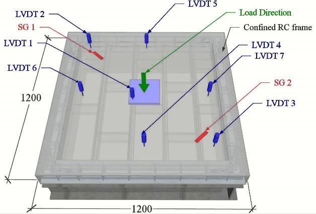
International Journal of GEOMATE, May., 2021, Vol.20, Issue 81, pp.188-193

    Four interlocking concrete block models were                  Four-cylinder samples were taken from each
developed in the upcoming research with various                model by drilling to investigate the concrete block's
height hooks, as shown in Fig. 1. Each model has               compressive strength. Each sample had a diameter
three different height hooks, i.e., 15, 20, and 25 mm,         of 50 mm and a height of 100 mm. The test results
where the unit is a standard concrete block with a             of material properties for the interlocking concrete
dimension of 400×220×100 mm. The concrete                      block and mortar are listed in Table 1. The mortar
block type-A was used in the confined masonry                  used for adhesive and plastering of all wall surfaces
walls proposed in this research.                               was the same material composition of concrete
                                                               block with a water-cement ratio of 0.5 as shown in
                                                               Table 1. The primary reinforcing steels with a
                                                               diameter of 10 mm and the stirrup with a 6 mm
                                                               diameter were used for the reinforced concrete tie-
                                                               beam and tie-column. A concrete cylinder of 150
                                                               mm diameter and 300 mm in height was used to test
                                                               the compressive strength of concrete. Table 2
Fig. 1 Four models of interlocking concrete block              presents the test results.

Table 1 Compressive strength and modulus of elasticity of the material

  No.    Material                      Unit      Material           Average          Average         Average
                                       type    composition          density        compressive      modulus of
                                               (P.C.: sand)         (kg/m3)          strength        elasticity
                                                                                      (MPa)           (MPa)
    1    Concrete Brick (Core           A          1:4              1971.94            6.39           805.41
         drill, 50 mm diameter
                                        B          1:4              2033.06            7.13           844.86
         and 100 mm high)
                                        C          1:4              1992.82            6.34            820.52
                                        D          1:4              2025.35            5.73            826.74
    2    Mortar                                    1:4              2088.83           13.66              -
         (Cube 50x50x50 mm3)

Table 2 Observed material for the confined R.C. frame

   No.           Material               Average              Average              Average            Average
                                        density            compressive             tensile          modulus of
                                        (kg/m3)          strength (MPa)       strength (MPa)     elasticity (MPa)

    1    Concrete                       2342.97                39.20                 -                 29985
    2    Reinforcing steel, Ø6             -                     -                  313               193335
    3    Reinforcing steel, Ø10            -                     -                  361               218961

2.2 Confined Masonry Wall (CMW) Specimens
                                                                   After the concrete blocks' installation is
    Three 1200 x 1200 mm confined masonry wall                 complete, restraint is carried out by attaching the
specimens were prepared to be tested                           R.C. tie-beam-tie and tie-column. Each wall
experimentally with an out-of-plane load applied. In           specimen is plastered with a 10 mm thickness of the
this research, concrete block type-A with variations           mortar on all sides of the surface to increase the
hook height of 15, 20, and 25 mm was selected as               walls' strength to withstand a bending load. The
the wall forming material restrained by the R.C. tie-          CMW sample was installed horizontally and
beam and tie-column, forming a rigid portal. The               supported by four wall edges using the supporting
three specimens are named A15, A20, and A25.                   steel frame. The load was applied at the mid-center
Each sample was made of interlocking concrete                  of the wall perpendicular to the plane, as shown in
block layers, which were neatly arranged, and the              Fig.1.
gaps or spacing between the hooks were filled with
fine mortar to form a massive wall.

                                                         180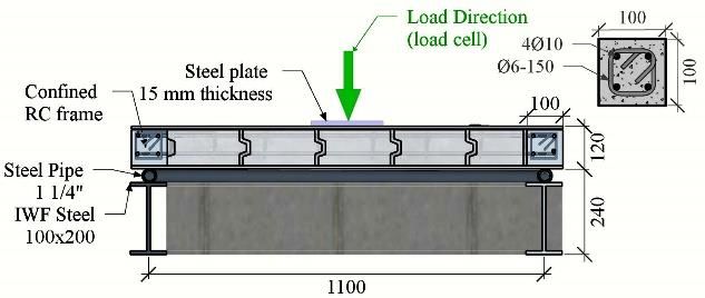
International Journal of GEOMATE, May., 2021, Vol.20, Issue 81, pp.188-193
Fig. 3 presents each sample with seven LVDT
instrumentations and two strain gauges installed.
Four LVDTs are fitted in the mid-length of the tie-
beam and column-tie elements; two LVDTs are
mounted at two wall corners. One LVDT is nestled
right at the load center point, and two strain gauges
are installed in the direction in line and
perpendicular to the diagonal line of the wall. The
out-of-plane load is incrementally applied at the
center point of the wall.
3. RESULTS AND DISCUSSION
(a) View of wall types: A-15, A-20, and A-25
The lesson learned from the critical note of the
post-large earthquake inspection results is that most
of the more extensive damage to the infill wall did
not occur at the top of the infilled frame. A more
considerable out-of-plane seismic action is
expected in these circumstances, but at the lower or
intermediate level, where higher in-plane drift
demand likely occurs [8-10]. This condition proves
that the masonry panel decreases the stability
(b) Section I-I outside its plane when subjected to in-plane action.
The simultaneous effect of seismic action within the
Fig. 2 Typical confined masonry walls in-plane and out-of-plane produces a decrease in the
in-plane deformation capacity due to out-of-plane
2.3 Out-of-plane Test Setups action and vice versa. The following sections
discuss the confined masonry wall's flexural
Further research on the out-of-plane seismic behavior, where the out-of-plane load is applied at
response of masonry infill walls is adopted to the wall's mid-center.
increase knowledge of the behavior and develop
effective strengthening strategies to prevent its 3.1 Behavior of Interlocking Concrete Block
collapse. However, such experimental tests are
challenging to conduct this research due to test As discussed above, a faster construction
equipment's inherent complexities, loading system has led to the change in masonry
approaches, and loading protocols [6-8]. construction's conventional approach to the
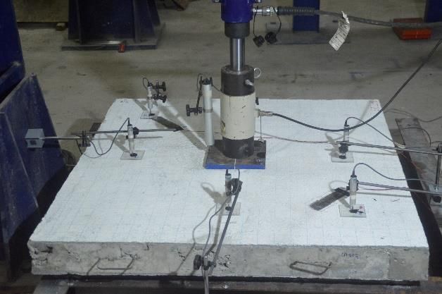
This study proposes a simple out-of-plane interlocking construction technique [11] as
experimental setup as depicted in Fig. 3. The wall proposed in this research. Lessons learned from the
specimen is positioned on a specially designed IWF most interlocking blocks available nowadays differ
100x200 steel frame to support the wall's four sides. in geometry, material composition, dimensional
On top of the steel portal, a 1.25-inch diameter steel characteristics, and compressive strength, including
pipe is installed around the perimeter to become the proposed concrete blocks. In general,
joint support. This specimen's clear span was interlocking concrete blocks can be laid without
measured from beam-tie and column-tie axles, as mortar layers and require less labor. Referring to
clearly shown in Fig. 1b. Ahmad et al. [12] and Maheri et al. [13],
interlocking masonry units used in this research
differ from traditional blocks that can be assembled
with geometrical features built into blocks without
the need for a mortar layer. This research, however,
combined mortar and hook systems in constructing
masonry walls using interlocking concrete blocks.
Furthermore, portland cement and fine sand with a
1: 4 mixture composition were used for mortar and
plaster. Mortal was used to attaching in between the
hooks.
Several factors that affect the main parameters
in masonry walls using interlocking concrete blocks
have been considered in preparing for the
specimens, for instance, the difficulty in ensuring a
Fig. 3 Experimental setup
181International Journal of GEOMATE, May., 2021, Vol.20, Issue 81, pp.188-193
strong adhesion between the mortar and the brick- selected masonry typologies like clay bricks and
hooks, no air voids in the joints between the concrete blocks were extended in this research.
concrete block hooks, the uniform mortar strength, Limited tests have been conducted for investigating
workability, and material quality. Fig. 4 shows how the out-of-plane response and even less in the
the concrete block interacts with each other to resist mutual in-plane/out-of-plane interaction on the
the out-of-plane load, demonstrating that the graphs interlocking concrete blocks.
of load and displacement responses measured from The out-of-plane or bending behavior of the
two different LVDT instrumentation points (4 and CMW is considerably more complex than the in-
5) have unsmoothly performed reached the plane behavior of walls. The walls can be subjected
maximum displacement at 19.12 mm. Furthermore, to bending in two directions. Consequently, it
a similar trend of the load-displacement becomes a statically, indeterminate structure. The
relationships measured from two other LVDT analysis of these walls is too complicated due to the
instruments at the wall corners serves lesser tensile strength in horizontal flexure is likely
displacement responses because the measuring several times greater than strength in vertical
point is farthest from the load center. The flexure. This difference may occur because the
displacements of the maximum loads recorded from vertical flexure commonly depends on the bed
the LVDT at points 2 and 3 vary from 3.89 to 8.86 joints' unit mortar interface's tensile bond strength,
mm, respectively. as proven in this research.
At the early stage of loading up to In contrast, the horizontal flexure depends on
approximately 50% of the maximum load, the the bed joints' friction resistance and the tensile
specimen provided adequate strength to resist the bond strength at the vertical joint interface [6].
out-of-plane load, where the vertical displacements Advanced finite element analysis by considering
were relatively small. It has been observed that the the interlocking system's complexity on the CMW
load increases until it reaches the ultimate load, in resisting the in-plane, out-of-plane, and diagonal-
displacement increases until it reaches the utmost shear loads will be carried out after the entire
condition. The load-displacement response trend research is completed. A technical paper on this
for the three hook height types measured from subject will be published elsewhere in an
different LVDTs shows similarities in the wall's international journal soon.
bending performance. In this research, an experimental setup was
developed using a different approach for applying
40
LVDT 4, A15 the out-of-plane loading, as shown in Fig. 3. This
35 LVDT 4, A20 paper provides an overview of the test setup adopted
30 LVDT 4, A25 in the literature by other authors and discusses their
25 LVDT 5, A15
implications in the CMW response. This research's
Load (kN)
LVDT 5, A20
20 LVDT 5, A25 point of interest lies in how the walls' optimal
15 performance to withstand the load perpendicular to
10 the plane as the bending structural behavior in
5 general. Fig. 5 illustrates the flexural behavior of the
0
CMW using the interlocking concrete block type-A
0 5 10 15 20 25 as a masonry infill. The LVDT recorded the load-
Displacement (mm) displacement response mounted at the wall center
during the incremental out-of-plane load applied
Fig. 4 Measured displacement at the LVDT-4 and until the ultimate stage reached.
LVDT-5
40
3.2 Out-of-plane Behavior of CMW 35 A15
30 A20
Building structures located in high seismicity A25
Load (kN)
25
zones are often subjected to lateral loads from 20
seismic actions, meaning that structural systems are 15
essentially designed to resist these loading types [5, 10
8]. In masonry buildings, the walls are the main 5
structural elements that carry on these actions: in-
0
plane and out-of-plane loads. In line with these 0 10 20 30 40 50 60 70 80
actions' cyclic random nature, any building wall is Displacement (mm)
most likely subjected to in-plane and out-of-plane
loads [9]. Fig. 5 Load-displacement responses
Previous experimental investigations [8, 9, 13]
focusing mainly on the in-plane seismic response on Three different types of CMW using the
interlocking concrete blocks A-15, A-20, and A-25
182International Journal of GEOMATE, May., 2021, Vol.20, Issue 81, pp.188-193
models were experimentally conducted to additional strength occurred. When the load
investigate their flexural behavior in supporting the gradually increased, the crack propagates along the
out-of-plane loads. As depicted in Fig. 5, the load- bed joint, and the damage mechanism immediately
displacement relationships have similar trends in formes with only a little residual strength due to the
their strength in withstanding the out-of-plane self-weight. In line with previous research [10-12],
loads. The results of specimen type A-15, A-20, and the horizontal flexural strength's general case is
A-25 show that the ultimate loads of the three more significant than its vertical strength, a crack
specimens have achieved the maximum loads of propagates along the bed joint under constant load,
34.4, 31.6, and 28.38 kN, respectively. The vertical and a stable state is reached. As load is further
deflections at the mid-point of the wall reached increased to achieve the ultimate loads, diagonal
48.47, 53.72, and 71.57 mm, correlated to the cracks immediately propagate to form a mechanism
displacement ductilities of 5.22, 5.61, and 5.83, leading to the wall failure, as depicted in Fig. 6.
respectively. It can be concluded that specimen type In this research, two strain gauges shown in Fig.
A-15 is a more compact wall element than other 7 were installed at the corners of the walls following
specimens, i.e., type-20 and type-25, and relates to the diagonal line. The strain gauges SG-1 and SG-2
their height hokes. Furthermore, the unsmooth were mounted in parallel and perpendicular
graphs were performed due to the interlocking directions to the diagonal line. The installation of
interaction between concrete block hooks and this strain gauge was intended to measure the strain
mortar paste during the out-of-plane load applied that occurred in the plaster during the
gradually. Besides, specimens with shorter hooks experimentation.
can withstand more loads but produce less vertical
40
deflection, and vice versa (Fig.6). SG 1, A15
35 SG 1, A20
3.3 Wall Failures Propagation 30 SG 1, A25
SG 2, A15
Load (kN)
25
SG 2, A20
As discussed earlier, the flexural wall behavior 20 SG 2, A25
depends mainly on the masonry confined panel's 15
boundary conditions. In the case of unreinforced 10
masonry walls supported on four sides, the vertical 5
bending moment at mid-height of the confined wall
0
induces tensile stresses in the direction of out-of- -6000 -4000 -2000 0 2000 4000 6000
plane bed joints. Since these stresses are higher than Microstrain
the tensile strength, a horizontal crack starts
propagating around the load point (Fig. 6).
Fig. 7 Strain gauge instrumentations
In general, the plaster has reached over the
maximum strain of 0.003 based on both strain gauge
measurements; however, not all specimens achieve
similar conditions. It should be noted that the strain
gauge installed parallel can measure more strain
than installed perpendicular to the diagonal line for
measuring the actual flexural stresses due to the out-
of-plane loads. The crack propagation in this
experimental test meets the yield line theory where
the diagonal crack starts propagating in line with the
increasing the applied load.
4. CONCLUSION
In conclusion, the interlocking concrete block
development presented in this study has confirmed
Fig. 6 Cracks propagation surrounding the point of that this system is potentially utilized in future
load applied masonry structures. Accordingly, the concept of the
interlocking system is suitable for replacing the
Fig. 6 illustrates the wall failure propagation, conventional method. It can be concluded that the
showing that the cracked wall's behavior depends shape of the interlocking concrete block varies with
on the masonry's orthogonal flexural strength. simplicity, which produces easy and fast production
Furthermore, the vertical flexure strength is the and assembly in the CMW systems. Moreover, all
same as the horizontal flexure strength; and no the interlocking concrete blocks' mechanism is
183International Journal of GEOMATE, May., 2021, Vol.20, Issue 81, pp.188-193
sufficient to interlock the assembled concrete [6] Najafgholipour M. A., Maheri M. R, and
blocks in different directions. Based on the Lourenço P. B., Capacity Interaction in Brick
researches of the flexural behavior of interlocking Masonry under Simultaneous In-plane and
concrete blocks in resisting the out-of-plane load, it Out-of-plane Loads, Construction and
can be summarized that the interlocking concrete Building Materials, Vol. 38, 2013, pp. 619-
blocks have met the minimum specifications and 626.
requirements as per SNI 03-0349-2989 Standards [7] Al-Fakih A., Mohammed B. S., Nuruddin F.,
(Indonesian National Standard). It also verified that and Nikbakh D., Development of Interlocking
interlocking concrete blocks could be used either as Masonry Bricks and Its' Structural Behaviour:
a load-bearing wall or a non-load bearing system. A Review Paper IOP conference series: Earth
and Environmental science, volume 140, the
5. ACKNOWLEDGEMENTS 4th ICONCEES, 4–5 December 2017,
Langkawi, Malaysia.
The authors would like to express their gratitude [8] Griffith M.C., Vaculik J., Lam N. T. K,
to the Directorate General of Higher Education of Wilson J., and Lumantarna E., Cyclic testing
Indonesia for granting their financial support to this of unreinforced masonry walls in two-way
research and the Department of Civil Engineering bending, Earthquake Engng Struct. Dyn. Vol.
at the Islamic University of Indonesia for allowing 36, 2007, pp. 801–821.
for the use of all of the research instruments that [9] Tanjung J., Maidiawati, and Alfajri A., Effect
were utilized. A special thank goes to Mr. Zakki of Brick Masonry Infills to Seismic Capacity
Rizal for his assistance during the experimental of Indonesia Multi-Story R.C. Building,
tests and capturing the data. Note: research contract International Journal of GEOMATE, Vol 16,
no: 227/SP2H/AMD/LT/DRPM/2020. Issue 57, 2019, pp 42-48.
[10] Furtadho A., Rodrigues H., Arede A., and
6. REFERENCES Varum H., Experimental evaluation out-of-
plane capacity of masonry infill walls,
[1] Haach V. G., Vasconcelos G., Lourenço P. B., Engineering Structures, Vol. 111, 2016, pp.
Experimental Analysis of Reinforced 48-63.
Concrete Block Masonry Walls Subjected to [11] Singhal V. and Rai D. C., In-plane and out-of-
In-Plane Cyclic Loading, Journal of Structural plane behavior of confined masonry walls for
Engineering, April, 2010, pp. 1-39. various toothing and openings details and
[2] Haki S., Morandi P., Magenes G., and prediction of their strength and stiffness,
Sullivan T. J., Damage Control for Clay Earthquake Engng Struct. Dyn., 2016, pp. 1-
Masonry Infills in the Design of R.C. Frame 19.
Structures, Journal of Earthquake [12] Ahmad S., Hussain S., Awais M., Asif M.,
Engineering, 16(S1):1–35, 2012, pp. 1-35. Muzamil H., Ahmad R., and Ahmad S., To
[3] Cardone D. and Perrone G., Developing Study The Behavior of Interlocking of
fragility curves and loss functions for masonry Masonry Units/Blocks, IOSR Journal of
infill walls, Earthquakes, and Structures, Vol. Engineering, Vol. 04, Issue 03, March 2014,
9, No. 1, 2015, pp. 101-123. pp. 39-47.
[4] Teguh M., Experimental Evaluation of [13] Maheri R. M., Najafgholipour M. A., and
Masonry Infill Walls of R.C. Frame Buildings Rajabi A.R., The Influence of Mortar Head
subjected to Cyclic Loads, Procedia Joints on the In-plane and Out-of-plane
Engineering, Science Direct, Vol. 171, 2017, Seismic Strength of Brick Masonry Walls,
pp. 191-200. Conf. Proceeding of the 14th WCEE, October
[5] Maheri R. M., Najafgholipour M. A., In-plane 12-17, 2008, Beijing, China, pp. 1-9.
shear and out-of-plane bending capacity
interaction in brick masonry walls, Conf.
Copyright © Int. J. of GEOMATE. All rights reserved,
Proceeding of the 15th WCEE, September
including the making of copies unless permission is
2012, Lisboa, pp. 1-10. obtained from the copyright proprietors.
184You can also read