Control of an induction melting plant on a virtual machine
←
→
Page content transcription
If your browser does not render page correctly, please read the page content below
Induction Technology REPORTS
Control of an induction melting
plant on a virtual machine
by Erwin Dötsch, Jean-Pierre Hacquin, Dietmar Mitschulat
The Kempten iron foundry Adam Hönig AG has introduced a data management system on its way to Industry 4.0, with
which the manufacturing processes of the diverse production program are made transparent via app and smartphone.
In this context, high demands are made on the control of the two induction furnace tandem systems, which are fully met
by the ABP melt processor Prodapt-Enterprise in combination with virtual systems and an in-house server. The consistent
acquisition and evaluation of the process data brings savings in the use of energy and materials.
T
he Kempten iron foundry Adam Hönig AG (KE, Fig. 1) is while the 3 t furnaces are only supplied with the cold start
a family-owned company that has been in existence program from 4:00 o’clock, also at 1,000 °C melt tempera-
for more than 60 years. As a job shop foundry with ture by 6:00 o’clock and are ready for full power.
mold construction and design consultancy, it manufactures
cast iron parts primarily for mechanical engineering. Castings
in gray and nodular cast iron are cast in a hand-molding
shop and in an automated machine shop with part weights
of a few kilograms up to 8.5 t in one-off production as well
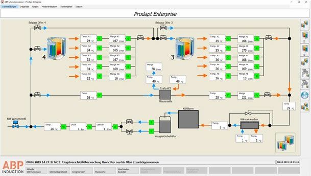
as in small and medium production runs (Fig. 2). The
variety of products is in the range of 6,000 to 7,000 diffe
rent models. Fig. 3 shows some examples of average
casting weight. 170 employees produce about 1,000 t
of good castings per month. KE is certified according to
DIN EN ISO 9001: 2019 and maintains a high quality and
environmental standard.
The variety and quantity diversity of the liquid iron Fig. 1: Iron Foundry Adam Hönig AG in Kempten, Allgäu (Germany)
requirement requires a flexible melting plant. This require-
ment is met by two ABP induction furnace tandem sys-
tems. Tandem 1 consists of two 3 t crucible furnaces, type
ITMK 6000, which are powered by an 1,800 kW / 250 Hz
inverter. Two 6 t crucible furnaces, type FS 60 (Fig. 4), form
the second tandem powered by a 3,500 kW / 250 Hz invert-
er. Both furnaces are equipped with the TwinPower system,
so that their power can be distributed electronically to the
two associated furnaces in any ratio [1].
The melting plant is operated in a single-shift process.
In each case after the last tapping the melt is charged for
the start of the first batch of the next production layer
in the hot crucible. The furnaces then cool to near room
temperature and then re-melt at 6:00 in the morning. For
this purpose, the 6 t furnaces are automatically ramped up Fig. 2: Pouring of an 8,5 t-machine-base
from 3:00 o’clock with the cold start program to 1,000 °C,
1-2020 heat processing 51
Lizensiert für: Ulrike Szymura
© Vulkan-Verlag GmbH - 08/2020
REPORTS Induction Technology
Fig. 3: Beams of EN-GJS-400-15, each 484 kg
KE DEVELOPMENTS ON THE WAY optimising it so that energy and material use can be saved
TO INDUSTRIE 4.0 [2]. For this purpose, the process data from the gating and
With the support of Kempten University of Applied Sciences the mold production to the unpacking of the cast blanks
and funding from the German Environmental Foundation are recorded and evaluated. The digital monitoring is carried
(DBU), KE has introduced a data management system with out by app on smartphones, where barcodes are used
the aim of making the production process transparent and on the pans and boxes, which the employee scans and
transmits to a database (Fig. 5). That way it is possible to
track which box was filled with which melt at which time.
This, for example, gives you the opportunity to process
important components faster without increasing your
production capacity. Another advantage is the potential
increase in energy and resource efficiency by optimising
the ratio of foundry sand to melt and accurately melting
only the amount of metal that is actually needed for the
particular casting.
The specific energy consumption of the melting fur-
naces averaging 611 kWh/t of melt is an indication of the
benefits of data management. This value should be seen
in the context of the single-shift operation and the pro-
duction program: Firstly, in the daily cold start, the heat of
Fig. 4: 6 t / 3,500 kW – Induction-furnace-tandem, type ABP FS 60 storage of the refractory lining must be applied each time
and, secondly, the provision of melt amounts above the
capacity of a single furnace inevitably results in high hol
ding times. Under these conditions, the energy expenditure
of just over 600 kWh/t is a favourable value, which can be
attributed to transparent production logistics.
In this context, the control of the melting plant is of central
importance. The demanding conditions for the implementa-
tion of the described data management system on the part
of the smelting operation were created by the installation of
the ABP control system Prodapt-Enterprise in conjunction
with an in-house server based on virtual systems.
CONTROL USING VIRTUAL SYSTEMS
The PC systems used in foundries are often only partially
Fig. 5: Scanning of a flask barcode utilised to capacity. As a result, resources remain unused
which leads to higher operating costs. One way out of this
unsatisfactory situation is the use of virtual systems at KE. It
52 heat processing 1-2020
Lizensiert für: Ulrike Szymura
© Vulkan-Verlag GmbH - 08/2020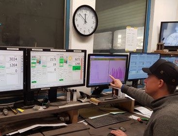
Induction Technology                      REPORTS

         Fig. 6: Hardware concept for the melting operation

uses special software to simulate hardware functions and            according to the program prescribed by the work prepara-
create virtual machines. This allows multiple computers             tion and transferred to the automatic charging crane. This
with different operating systems to run on one server.              then loads the calculated amounts of materials into the
In addition to better utilisation of the server, this leads to      charging trolley, from where they are charged according
higher availability of the applications as the susceptibility       to the requirements into the crucible and melted. At the
to hardware failures decreases. The hardware concept for            same time, the additives also specified by the charging
the KE melting operation is shown in Fig. 6.                        system computer are charged by hand from the furnace
    On the central server, the virtual machines are installed       platform into the crucible. The sample drawn at the end
with the control systems for the different parts of the melting     of the melting process is analysed in the spectrometer
operation. The data exchange between the applications               and the result in the charge calculator compared with
on the virtual machines and the components in the field is          the target analysis. This is followed by the information for
based on TCP / IP based protocols. If field components are          the correction materials to be provided on the furnace
not network-capable, they are expanded by corresponding
devices and via a software known as connectors are inte-
grated into the data exchange.
    This makes it possible to record a large part of all process-
relevant data of the individual subsystems and to store
them for cross-departmental analysis in a process database
so that the manufacturing process becomes comprehen-
sible for each casting. The monitoring of this production
data opens up the possibility of early detection of errors
and the initiation of corresponding countermeasures.
    Modern systems monitor themselves and inform the
operator when the unit leaves the normal operating range.
In this context, the system performs extended monitoring
of the cooling systems for the furnace and converter circuit
as well as the cooling station. These data can be exchanged
between the operator and the furnace system manufac-
turer and form a first step in the direction of a rule-based
plant monitoring.
    To control the melting process, the subsequently
described melt processor Prodapt-Enterprise is used. With                 Fig. 7: Monitoring of the melting operation in the control room
the charging system the batch composition is determined

1-2020   heat processing                                                                                                                     53
                                                           Lizensiert für: Ulrike Szymura
                                                         © Vulkan-Verlag GmbH - 08/2020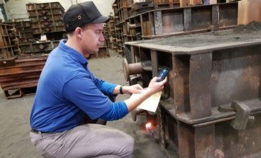
REPORTS Induction Technology
MELT PROCESSOR PRODAPT-ENTER-
PRISE
The ABP Prodapt-Enterprise processor provides a complete
melting process control solution. It supports the operator
in guiding the furnace in sintering, melting and cold start
modes. The process screens on the monitor inform the
operator quickly and comprehensively about the situation
of the melting process, pending faults and the measured
parameter values (Fig. 7). In addition to economical
operation, high availability and operational reliability of
the melting system is achieved.
The process screens are designed so that the user can
access the trend of the measured values in addition to the
current data with a mouse click. In addition, in the fault
message system the individual messages can be assigned
Fig. 8: Overview screen of the 6 t-tandem instructions in the form of pictures and texts.
As an example, Fig. 8 shows the overview screen of
the 6 t tandem with the furnaces 3 and 4. During the
normal melting process, this image is displayed on the
monitor above the control panel and provides the opera-
platform. The additional additives specified by the charge tor with clear information about the current events in the
computer are taken into account, prepared on the foundry furnaces. The large numbers indicate from top to bottom:
floor, and added to the ladle during tapping. crucible contents in kg, melt temperature in °C, power in
In addition to the spectrometer, a thermal analysis for kW. The horizontal green bar (under the furnace image)
the control of the melt quality is randomly applied. There, is a measure of the lining wear, which will be discussed
the C and Si contents are determined and a so-called in more detail later. Below this are the batch and material
K factor as a measure of the nucleation state of the melt. numbers along with an index number for the operator. The
1
Fig.9: Supervision screen of the furnace cooling system
54 heat processing 1-2020
Lizensiert für: Ulrike Szymura
© Vulkan-Verlag GmbH - 08/2020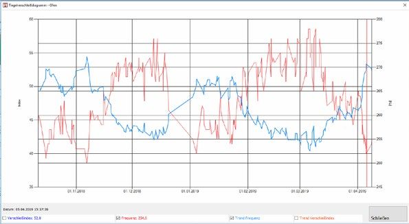
Induction Technology REPORTS
Fig. 10: Graph of the crucible wear figures over several campaigns. Blue: Frequency; Red: Wear factor
vertical orange bar indicates the amount of furnace power. violations, warnings are generated and forwarded to the
The required traceability of the melting process is maintenance department.
taken into account by the Prodapt-Enterprise by linking The fast and targeted reaction in case of failure is an
the order number and the melt number to insure corre- essential factor for the availability of the melting plant. For
lation. In addition, the work carried out on the furnace is this purpose, there is a plain text message when a fault
logged. In addition to the general data of the melt, this occurs in the header of the process pictures. According to
logging stores the course of treatment with one-minute their classification, the displayed message is highlighted. This
resolution. The course of treatment includes the heating information is supplemented by the detail screen “Shut-
process as well as the process events such as scale taring, downs”. This detail image lists the malfunctions that cause
temperature measurement and tapping. For each event, the entire system or the relevant furnace to be switched off.
the time, duration, furnace contents and temperature of The operator receives the fault information per SMS addi-
the melt are recorded. In addition, the characteristics of the tionally which is helpful during down times, for example
selected material and the measured analyses are archived in case of cold start during the night.
in the process database.
In addition to process control, the visualisation of the MONITORING THE CRUCIBLE WEAR
Prodapt-Enterprise captures the current status of the The crucible monitoring has a special significance for the
cooling system, hydraulics and energy supply. Limits that trouble-free operation of the melting plant. In addition
are exceeded or disturbances are represented by colour to the regular visual inspection after tapping while the
changes in the measuring fields and symbol fields. The crucible wall has a dark red surface, monitoring is done by:
furnace cooling system supervision screen shown in Fig. 9 ■ Checking the resistance between the melt and coil
is representative of these screens. (ground fault indication)
The collected data is shown in a schematic rep- ■ Measurement and evaluation of active power and
resentation of the system. The measurement fields show frequency using the Prodapt-Enterprise.
not only the values but also limit violations by colour
change, and by clicking the trend of the value over the The ground fault indication system is described in detail
last 8 h can be viewed. The symbols are animated, and elsewhere [3]; Here, the second method, namely the use
the status is indicated by colour changes. The system of the Prodapt data will be discussed in more detail. Their
also records the water temperatures and volumes of significance in terms of crucible wear is due to the change
the individual furnace cooling circuits. In case of trend in inductance of the coil as its distance from the melt
1-2020 heat processing 55
Lizensiert für: Ulrike Szymura
© Vulkan-Verlag GmbH - 08/2020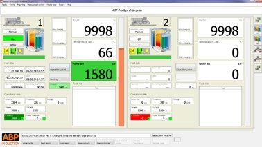
REPORTS       Induction Technology

               changes. Accordingly, active power and frequency increase         quality or algorithms will be developed on the basis of the
               with decreasing wall thickness. In melting operation, once        available data, which will further improve the coordination
               per batch with a full furnace and defined temperature,            between the melting and casting shops. Furthermore, the
               always at the same measuring conditions, the frequency            improvement of quality in the process chain is conceivable.
               and an index number for wear are determined. The latter           With the aid of process data acquisition and evaluation of
               is calculated from the specified power and the ratio of the       tolerances, errors can be derived from deviations. For this
               resulting voltage to the rated voltage.                           purpose, automatically generated algorithms can be used
                   The values determined for the frequency and the wear          which are specially designed for the foundry process.
               index number are plotted over time and displayed in a
               process graph over the course during a lining campaign.           LITERATURE
               Fig. 10 shows an example of the graph of the measured             [1] Dötsch, E .: Inductive melting and holding. 3rd edition. Essen:
               values over several campaigns. At the end of a crucible               Vulkan Verlag, 2019
               campaign, the graphs are compared and correlated with
               the current condition of the worn crucible. In this way, it is    [2] https: // www. hs-kempten.de/home/news-details/article/
               possible to deduce from the course of the next campaign               3975indus.html
               the expected crucible life and the time of re-lining.
                   A simplified and clear depiction of the wear process is       [3] Dötsch, E., Forsthövel, Ch.; Rische, M.: Coil and crucible moni-
               shown in the overview process images (Fig. 8). There the              toring during the melting operation of induction crucible fur-
               measured values of frequency and power are converted                  naces. ewi – elektrowärme international (2013) No. 1, pp. 54-58
               to the length of a bar. At the beginning of a lining cam-
               paign, the horizontal green bar has the full length; it then
               decreases with progressively thinner crucible wall until
               complete disappearance when reaching the predeter-                                   AUTHORS
               mined minimum wall thickness.
                   The term INTEGRAL is a characteristic statement for                              Dr.-Ing. Erwin Dötsch
               the evaluation of this signal. It follows from the physical                          ABP Induction Systems GmbH
               contexts that the described determination of the measured                            Dortmund, Germany
               values characterising the wall thickness always relates to                           +49 (0)231 / 997-2451
               the entire crucible in the area of the active coil. A local                          erwin.doetsch@abpinduction.com
               refractory wear in the form of an annular wear or a so-called
               elephant’s foot is averaged over the entire crucible and
               accordingly not identified in its extent. As mentioned at                            Jean-Pierre Hacquin
               the beginning of this section, therefore, the Prodapt signals                        Kemptener Eisengießerei Adam Hönig AG
               must always be interpreted in the context of expert visual                           Kempten (Allgäu), Germany
               inspection. In this way, INTEGRAL offers reliable and clear                          +49 (0)831 / 58110-34
               help with crucible evaluation.                                                       EDV@ke-ag.de

               OUTLOOK
               The benefits of end-to-end data management, beyond                                   Dietmar Mitschulat
               the goals already achieved, can be further expanded on as                            ABP Induction Systems GmbH
               plant builders and operators work together. For example, it                          Dortmund, Germany
               is conceivable that the results of the thermal analysis will be                      +49 (0)231 / 997-2526
               more closely integrated into the improvement of the melt                             dietmar.mitschulat@abpinduction.com

                +++ www.heat-processing.com +++ www.heat-processing.com +++

56                                                                                                                           heat processing   1-2020
                                                        Lizensiert für: Ulrike Szymura
                                                      © Vulkan-Verlag GmbH - 08/2020
You can also read