Computationally efficient real-time digital predistortion architectures for envelope tracking power amplifiers
←
→
Page content transcription
If your browser does not render page correctly, please read the page content below
International Journal of Microwave and Wireless Technologies, 2013, 5(2), 187–193.   # Cambridge University Press and the European Microwave Association, 2013
doi:10.1017/S1759078713000135

research paper

Computationally efficient real-time digital
predistortion architectures for envelope
tracking power amplifiers
     pere l. gilabert and gabriel montoro

       This paper presents and discusses two possible real-time digital predistortion (DPD) architectures suitable for envelope track-
       ing (ET) power amplifiers (PAs) oriented at a final computationally efficient implementation in a field programmable gate
       array (FPGA) device. In ET systems, by using a shaping function is possible to modulate the supply voltage according to differ-
       ent criteria. One possibility is to use slower versions of the original RF signal’s envelope in order to relax the slew-rate (SR) and
       bandwidth (BW) requirements of the envelope amplifier (EA) or drain modulator. The nonlinear distortion that arises when
       performing ET with a supply voltage signal that follows both the original and the slow envelope will be presented, as well as the
       DPD function capable of compensating for these unwanted effects. Finally, two different approaches for efficiently implement-
       ing the DPD functions, a polynomial-based and a look-up table-based, will be discussed.

Keywords: Power amplifiers and linearizers, Modeling, Simulation and characterizations of devices and circuits

Received 1 October 2012; Revised 18 January 2013; first published online 5 March 2013

I.   INTRODUCTION                                                                     considering current wideband signals with high PAPR.
                                                                                      There are already some companies, such as Nujira (www.
Alternatives to the classical Cartesian transmitter that uses                         nujira.com), MaXentric (www.maxentric.com) or Quantance
linear power amplifiers (PAs) with constant supply are being                           (www.quantance.com) that are offering ET solutions with
investigated to overcome the poor power efficiency with                                average efficiencies above 60% for WCDMA and LTE signals.
high peak-to-average power ratio (PAPR) signals. The                                      One of the main challenges of the EA consists of supplying
Doherty architecture, for example, has been adopted for base                          the power required by the transistor at the same speed of the
stations, where several manufacturers (e.g. Freescale, NXP),                          signal’s envelope. In dual-band applications, for example, this
are offering PAs with an average efficiency up to 50% and                              becomes even more challenging since the combined envelope
even more [1]. However, other promising structures such as                            can present BWs more than 5 × the carrier separation.
the envelope elimination and restoration (EE&R) [2, 3], the                           Therefore, in order to relax the EA requirements, some sol-
envelope tracking (ET), or polar transmitters with delta-sigma                        utions have been proposed to reduce the BW and slew-rate
modulation [4] are still being considered as candidates to                            (SR) of the original signal’s envelope [5–8]. Unfortunately,
overcome the Doherty PA efficiency. From the implemen-                                 the use of a slower version of the envelope to supply the PA
tation point of view, ET is a very attractive technique                               drain not only degrades the overall efficiency but also results
because it can be applied in conventional transmitters based                          in nonlinear distortion amplification. Despite the efficiency
on linear RF amplification topologies by simply substituting                           and linearity degradation, the solution of supplying the PA
the classical static supply for a dynamic one.                                        with a slower envelope can still be of interest in applications
    One of the main constraints in the maximum efficiency                              where it is necessary to trade-off the BW and efficiency due
that can be achieved by ET transmitters regards the envelope                          to the EA limitations. To compensate the nonlinear distortion
modulator of the envelope amplifier (EA), since the overall                            that arises when using the SR’s limited version of the original
efficiency of an ET architecture is the product between both                           envelope, it will be necessary to use a slow envelope-
the PA and the EA power efficiency. The envelope bandwidth                             dependent digital predistorter (SED-DPD) [5, 9, 10].
(BW) is several times (theoretically is infinite) the BW of the                            Therefore, this paper is organized as follows. The BW
baseband complex modulated signal, which is critical when                             versus efficiency trade-off in EAs will be discussed in
                                                                                      Section II. The design of the DPD that is required to compen-
                                                                                      sate for the nonlinear distortion that arises when supplying
Department of Signal Theory and Communications, Universitat Politècnica de           with a slower version of the signal’s envelope, will be pre-
Catalunya-BarcelonaTech, c/ Esteve Terradas 7, 08860 Castelldefels, Barcelona,        sented in Section III. Some field programmable gate array
Spain
Corresponding author:
                                                                                      (FPGA)-oriented implementation architectures for real-time
Pere L. Gilabert                                                                      DPD will be discussed in Section IV. Finally, in Section V con-
Email: plgilabert@tsc.upc.edu                                                         clusions will be given.

                                                                                                                                                                 187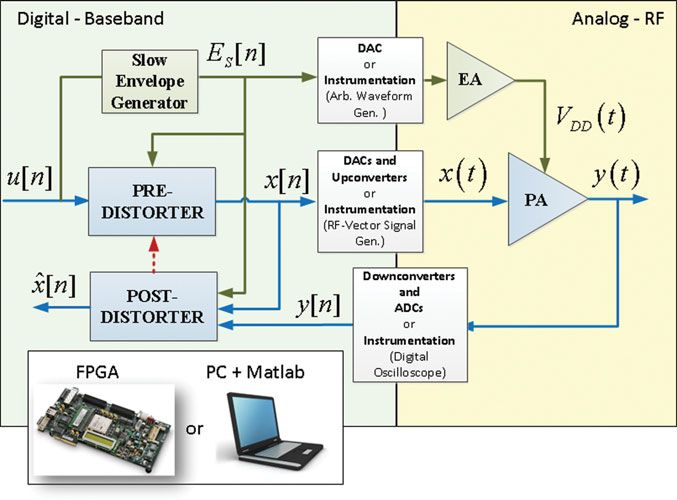
188     pere l. gilabert and gabriel montoro

      II. DYNAMIC SUPPLY OF THE PA                                                  envelope iteratively, which may represent an issue in real
      WITH SLOW VERSIONS OF THE                                                     time applications. On the other hand, the method proposed
      SIGNAL’S ENVELOPE                                                             in [8] consists of a real-time algorithm where the resulting
                                                                                    signal is limited in SR but not in BW, making challenging
      In an ET system (see Fig. 1), the supply voltage is dynamically               its amplification if only a switched mode EA is considered
      adjusted to track the RF envelope at high instantaneous                       or requiring a wide band if only a linear EA is considered.
      power. The supply voltage can be shaped according to differ-                  Therefore, in [14], the SR reduction algorithm proposed in
      ent criteria. By means of a so called shaping function it is pos-             [8] was modified in order to also restrict the BW of the result-
      sible to accommodate the shape of the supply voltage (that                    ing slow envelope. Moreover, due to its simplicity this algor-
      somehow must follow the instantaneous RF envelope) to                         ithm is suitable to be implemented in a digital signal
      achieve the following objectives: optimum efficiency, isogain                  processor. Fig. 2 shows the original RF signal’s envelope, an
      [11–13] or SR and BW reduced shaping [14].                                    SR reduced version of the original envelope (SR reduced
         Focusing on this later objective, two different approaches                 envelope – SRRE) and a BW reduced version of the original
      based on SR and BW reduction of the RF signal’s envelope                      envelope (BW reduced envelope – BWRE) in both time and
      showed that these strategies are suitable to adapt the envelope               frequency domains, respectively. The parameter N (defined
      characteristics to the EA requirements or limitations at                      in [8]) is related to the maximum allowed increment in the
      the expenses of having efficiency degradation. On the one                      signal’s slope. For example, N ¼ 100 corresponds to an SR
      hand, the method proposed in [5, 6] limits the BW of the                      reduction of 96% and BW reduction of 64% with respect to

      Fig. 1. General block diagram of an ET PA with DPD.

      Fig. 2. Waveforms and spectra of the envelope and its SR and BW limited versions [14].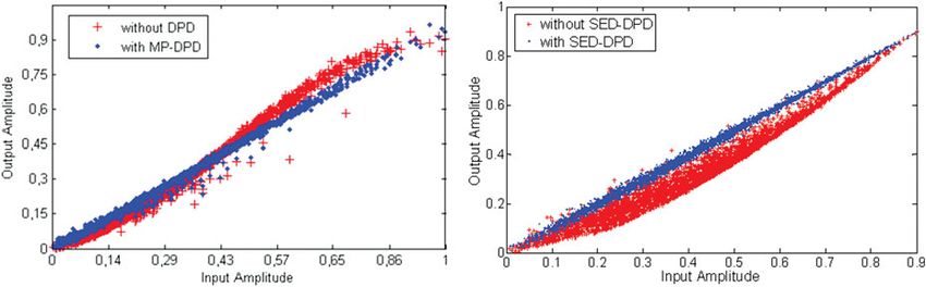
digital predistortion architectures for envelope tracking power amplifiers 189
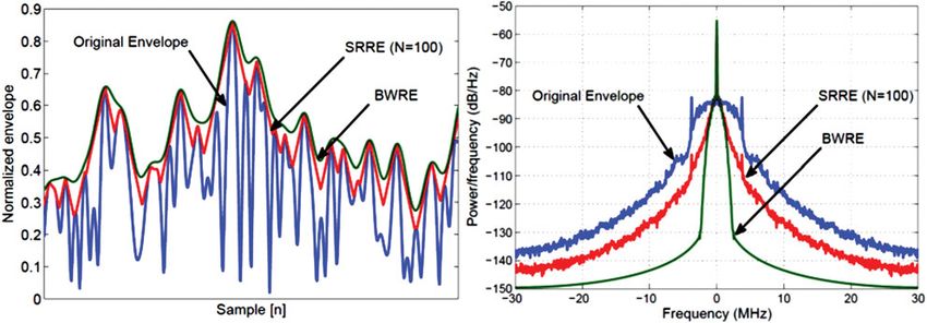
Fig. 3. AM–AM characteristics of the PA when considering only three margins of Es (left) and taking into account all possible values of Es (right).
the original signal’s envelope. The results shown in Fig. 2 were where nonlinear functions fi(.) can be described by poly-
extracted from the implementation of this algorithm on a nomials of order P
FPGA Virtex-4 whose clock speed was set to 60 MHz.
As reported in [15], the efficiency decays more or less lin-
early with the BW reduction, while it presents a logarithmic
P
fi (|u[n − ti ]|) = gpi |u[n − ti ]|p = g0i + g1i |u[n − ti ]|
behavior with the SR reduction. As a consequence, when con-
p=0
sidering applications with high BW signals (e.g. dual-band
transmissions) it is possible to find a trade-off solution to + · · · + gPi |u[n − ti ]|P . (2)
meet both SR and BW requirements of the EA while still
keeping a reasonably good drain efficiency figure.
Unfortunately, using the SR and BW limited envelope (or As previously explained, when considering the slow envelope
simply slow envelope – Es) to supply the power transistor’s to supply the PA, the nonlinear distortion that appears cannot
drain generates a particular nonlinear distortion. Fig. 3 be compensated by simply using dynamic behavioral models
shows the AM–AM characteristics considering different such as the MP [10]. Therefore, in [9] a dynamic SED behav-
margins of Es values. As observed in Fig. 3, the ET PA ioral model is proposed to compensate for this type of non-
shows a nonlinear variant gain because the slow envelopes linear distortion. The input–output relationship of the
used to supply the PA and the RF input signal are not univo- SED-DPD is defined as
cally related. Therefore, for a given input it is possible to have
a range of different outputs because it depends on the specific
value of the dynamic power supply. Therefore, the ET PA pre-
M
Q
N
P q
x[n] = gpiqj Es [n − tj ] u[n − ti ]|u[n − ti ]|p ,
sents a SED nonlinear behavior. j=0 q=0 i=0 p=0
(3)
III. DESIGN OF A REAL-TIME DPD
FOR ET where Es[n] is the SR-limited version of the original envelope,
u[n] is the input signal, tj and ti (with t0 ¼ 0) are the most
The type of low-pass equivalent black-box behavioral model significant tap delays of the slow envelope and input signal,
required to characterize the nonlinear distortion that arises respectively, contributing to the characterization of memory
when applying ET is dependent on the strategy (or shaping effects.
function) followed to supply the PA. Therefore, on the one Figure 4 shows linearized and unlinearized AM–AM
hand, if the PA drain voltage follows the same shape (despite characteristics of an ET PA when supplying the PA with the
being bounded at low-voltage levels) than the RF signal’s original envelope (MP DPD used) and with a slower version
envelope, typical behavioral models such as the memory poly- of the original envelope (SED-DPD used). The linearity per-
nomial (MP) [7] can be used for DPD purposes. On the other formance in terms of out-of-band distortion compensation
hand, if the slow envelope is used to supply the PA, then the of the SED-DPD can be observed in Fig. 5. These particular
DPD has to include the information of the slow envelope in results were measured on a test-bed based on instrumentation,
order to be capable of compensating for this type of nonlinear schematically depicted in Fig. 1 and described in [10]. The
distortion. Device under test (DUT) is a Cree Inc. Evaluation Board
For the case of using the original envelope, we can consider CGH40006P-TB (GaN transistor) at 2 GHz operating at a
the implementation of a DPD based on the simple MP model. mean output power of 28 dBm. For the sake of simplicity, a
Following the notation in Fig. 1, the input–output relationship linear IC LT1210 was considered as the envelope driver. The
of the MP DPD is defined as PAPR of the signals at baseband range from around 8 up to
11 dB, depending on the type of signal used (single-carrier
N M-QAM or OFDM). In the case of the SED-DPD, we used
x[n] = u[n − ti ]fi (|u[n − ti ]|), (1) the following configuration: P ¼ 9, Q ¼ 2, M ¼ 3 and N ¼ 1
i=0 (alternatively, N ¼ 0).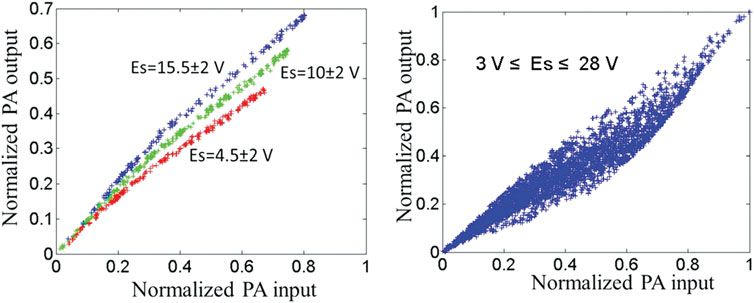
190     pere l. gilabert and gabriel montoro

      Fig. 4. Linearized and unlinearized AM-AM characteristics of an ET PA considering: (a) the original envelope (left), (b) a slow envelope (right).

      Fig. 5. Unlinearized and linearized (dynamic SED-DPD) output power spectra of a single-carrier 16-QAM (left) and OFDM 16-QAM (right) signals, respectively.

      Fig. 6. Block diagram of the MP DPD (left) and the SED-DPD (right).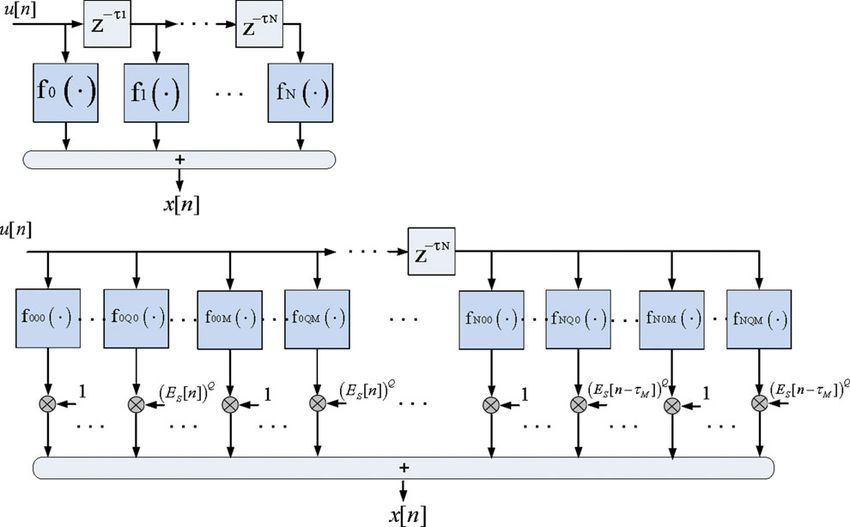
digital predistortion architectures for envelope tracking power amplifiers                                 191

IV. FPGA IMPLEMENTATION                                                         additions), resulting in P(P+7)/2 arithmetic operations for a
ARCHITECTURES                                                                   polynomial of degree P. While using the formulation in (4),
                                                                                computation starts with the innermost parentheses using the
The FPGA implementation of an MP DPD will follow the                            coefficients of the highest degree monomials and works
structure presented in Fig. 6. Each branch represents one                       outward, each time multiplying the previous result by
nonlinear function expressed by means of a polynomial devel-                    |u[n − ti ]| and adding the coefficient of the monomial of
opment. To allow an accurate and efficient FPGA implemen-                        the next lower degree. Now it takes 4P arithmetic operations
tation of the MP DPD it is important to minimize the number                     for a polynomial degree of P, which for high polynomial
of arithmetic operations (counting both additions and multi-                    orders, Horner’s algorithm results much more computationally
plications) and minimize the accumulative error inside the                      efficient. Figure 7 shows the structure of the nonlinear branches
FPGA. Both issues can be addressed using the Horner’s rule                      of the MP DPD in Fig. 6. Alternatively, instead of using poly-
and this way limiting the number of consecutive complex                         nomials to describe nonlinear functions fi(.) it would have
multiplications to a maximum of two. Moreover, as presented                     been possible to use basic predistortion cells (BPCs) [17]. A
in [16], in order to avoid a large variation in magnitude of the                BPC is composed of a RAM block acting as a look-up table
polynomial coefficients (which requires a large number of bits                   (LUT), an address calculator and complex multipliers.
to preserve the precision of the computation) it is possible to                    In order to implement the dynamic SED-DPD in an FPGA
take the ratios of adjacent coefficients. As a consequence, with                 device, the polynomial model in (3) is expressed as a combi-
a reformulation of (2) according to Horner’s rule, nonlinear                    nation of several BPCs [9]:
functions fi(.) can be described as

                              g1i
fi (|u[n − ti ]|) = g0i 1 +       |u[n − ti ]| 1 + · · ·
                                                                                                       P
                              g0i                                                      x[n] = u[n] ×           gp000 × |u[n]|p + · · · + (Es [n])Q
                                                                                                   p=0
       g(P−1)i                     g
     +         |u[n − ti ]| 1 + Pi |u[n − ti ]|          ···            (4)                                      G000 (·)
       g(P−2)i                   g(P−1)i                                                                          LUT


                                                                                                           P
                                                                                             × u[n] ×            gp0Q0 × |u[n]|p + · · · + u[n]
Therefore, taking into account the polynomial expression in                                                p=0
(2), where gpi [ C, it takes p + 1 real multiplications for
each monomial gpi u[n − ti ] p and 2P additions (P complex                                                        G0Q0
                                                                                                                     LUT
                                                                                                                         (·)

Fig. 7. Structure of one of the branches of the MP DPD (see Fig. 6) using Horner’s rule.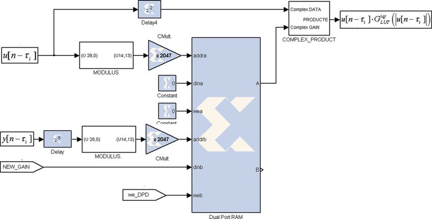
192     pere l. gilabert and gabriel montoro


                     P                                                                  Figure 6 shows the general block diagram of the SED-DPD
                 ×         gp00M × |u[n]|p + · · · + (Es [n − tM ])Q                 architecture, where nonlinear functions fiqj (.) can be
                     p=0                                                             expressed as a combination of BPCs. The number of BPCs

                                 G00M
                                  LUT
                                      (·)                                            forming this SED-DPD is # BPCs ¼ (Q + 1)(N + 1)(M + 1).
                                                                                     This structure requires less arithmetic operations than using

                                      P
                     × u[n] ×                 gp0QM × |u[n]|p + · · ·                polynomials; however, it consumes more memory resources.
                                      p=0                                               Figure 8 shows the basic structure of a BPC where a dual-
                                                                                    port RAM, with two independent sets of ports for simul-
                                                    G0QM (·)
                                                     LUT                             taneous reading and writing, is used to allow the complex

                                                P                                    LUT gains to be updated continuously without interrupting
                     + u[n − tN ] ×                    gpN00 × |u[n − tN ]|p         the normal data transmission. Therefore, because of this
                                                 p=0                                 LUT-based architecture, it is possible to perform continuous

                                                               GN00
                                                                LUT
                                                                    (·)              adaptation of the DPD function by means of the least-mean
                                                                                     squares (LMS) algorithm [17].
                     + · · · + (Es [n])Q × u[n − tN ]]
                                                                               (5)

                         P
                     ×           gpNQ0 × |u[n − tN ]| + · · ·   p

                           p=0                                                       V.   CONCLUSION

                                            GNQ0
                                             LUT
                                                 (·)
                                                                                     In this paper, we have presented and discussed two computa-

                                                P
                                                                                     tionally efficient design strategies for implementing real-time
                     + u[n − tN ] ×                    gpN0M × |u[n − tN ]|p
                                                 p=0
                                                                                     DPD in a FPGA device when considering ET PAs. As dis-
                                                                                    cussed along the paper, when considering slow versions of
                                                               GN0M
                                                                LUT
                                                                    (·)              the original envelope to perform ET, the nonlinear distortion
                     + · · · + (Es [n − tM ])Q × u[n − tN ]                          that appears has to be compensated using DPD architectures
                                                                                     that depend not only on the input data and its memory, but

                         P
                                                                                     also on the drain voltage signal (slow envelope) and its
                     ×           gpNQM × |u[n − tN ]|p +,
                           p=0
                                                                                     memory. Two efficient architectures to allow real-time
                                                                                    FPGA implementation of the DPD function have been pre-
                                            GNQM
                                             LUT
                                                 (·)                                 sented. One solution is based on polynomials and the other
      which yields to the following expression of the SED-DPD:                       one is based on LUTs. The trade-off between those two con-
                                                                                     figurations is the number of arithmetic operations versus the

               M
                 Q
                   N                          q             iqj
                                                                                     memory resources requirements. In any case, the linearization
      x[n] =                       Es [n − tj ] u[n − ti ] × GLUT (|u[n − ti ]|)     performance of both architectures has been validated in
               j=0 q=0 i=0                                                           several papers [9, 16]. Finally, another key issue toward the
                                                                               (6)   computationally efficient FPGA implementation is the
                                                                                     design of identification/adaptation process. One possibility is
      with Giqj
            LUT being complex LUT gains.                                             the use of LMS-based solutions as in [17], where the

      Fig. 8. Basic architecture of a BPC forming the SED-DPD (see Fig. 6).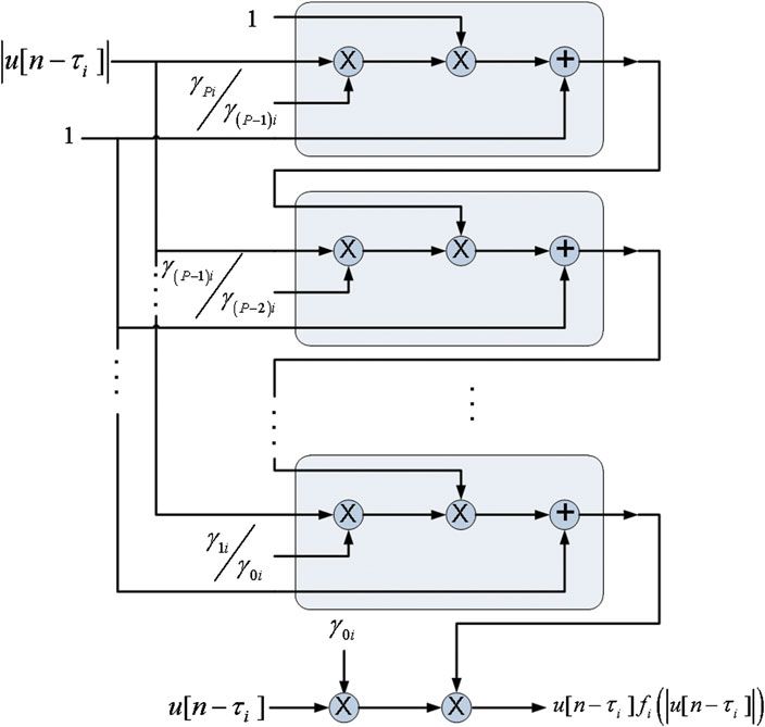
digital predistortion architectures for envelope tracking power amplifiers                                           193

coefficients (or complex LUT gains) are being continuously                       [11] Wimpenny, G.: Envelope Tracking PA Characterisation. White
updated. Alternatively, if more complex least-squares-type                           Paper. Open ET Alliance (http://www.open-et.org). November 2011.
algorithms are considered, the coefficient update procedure                      [12] Hanington, G.; Chen, P.-F.; Asbeck, P.M.; Larson, L.E.: High-
can be relocated to embedded software running on a micro-                            efficiency power amplifier using dynamic power-supply voltage
blaze soft processor core as in [18].                                                for CDMA applications. IEEE Trans. Microw. Theory Tech., 47
                                                                                     (1999), 1471–1476.
                                                                                [13] Hoversten, J.; Schafer, S.; Roberg, M.; Norris, M.; Maksimovic, D.;
                                                                                     Popovic, Z.: Codesign of PA, supply, and signal processing for
ACKNOWLEDGEMENT                                                                      linear supply-modulated RF transmitters. IEEE Trans. Microw.
                                                                                     Theory Tech., 60 (2012), 2010–2020.
This work was supported by the Spanish Government
(MINECO) under project TEC2011-29126-C03-02.                                    [14] Vizarreta, P.; Montoro, G.; Gilabert, P.A.: Hybrid envelope amplifier
                                                                                     for envelope tracking power amplifier transmitters, in European
                                                                                     Microwave Conf. (EuMC’12), Amsterdam, Holland, November
                                                                                     2012, 1–4.
REFERENCES                                                                      [15] Gilabert, P.L.; Montoro, G.; Vizarreta, P.: Slew-rate and efficiency
                                                                                     trade-off in slow envelope tracking power amplifiers, in German
 [1] Kim, B.; Kim, I.; Moon, J.: Advance Doherty architecture. IEEE                  Microwave Conf. (GeMiC’12), Ilmenau, Germany, March 2012, 1–4.
     Microw. Mag., 11 (2010), 72–86.
                                                                                [16] Mrabet, N.; Mohammad, I.; Mkadem, F.; Rebai, C.; Boumaiza, S.:
 [2] Raab, F.; Sigmon, B.; Myers, R.; Jackson, R.: L-band transmitter using          Optimized hardware for polynomial digital predistortion system
     Kahn EER technique. IEEE Trans. Microw. Theory Tech., 46 (1998),                implementation, in IEEE Topical Conf. on Power Amplifiers for
     2220–2225.                                                                      Wireless and Radio Applications (PAWR), Santa Clara, USA,
                                                                                     January 2012, 81–84.
 [3] Wang, F. et al.: An improved power-added efficiency 19 dBm hybrid
     envelope elimination and restoration power amplifier for 802.11 g           [17] Gilabert, P.L.; Montoro, G.; Bertran, E.: FPGA implementation of a
     WLAN applications. IEEE Trans. Microw. Theory Tech., 54 (2006),                 real-time NARMA-based digital adaptive predistorter. IEEE Trans.
     4086–4099.                                                                      Circuits Syst. II, 57 (2011), 402–406.
 [4] Taromaru, M.; Ando, N.; Kodera, T.; Yano, K.: An EER transmitter           [18] Julius, S.; Dinh, A.: Evaluation of a digital predistortion on FPGA for
     architecture with burst-width envelope modulation based on triangle             power amplifier linearization, in IEEE Canadian Conf. on Electrical
     wave comparison PWM, in Proc. IEEE Int. Symp. Personal, Indoor                  and Computer Eng. (CCECE), Montreal, Canada, May 2011, 660–664.
     and Mobile Radio Communications (PIMRC’07), Athens, Greece,
     September 2007, 1–5.                                                                             Pere L. Gilabert received the degree in
 [5] Jeong, J.; Kimball, D.F.; Kwak, M.; Hsia, C.; Draxler, P.; Asbeck, P.M.:
                                                                                                      Telecommunication Engineering from
     Wideband envelope tracking power amplifiers with reduced                                          UPC in 2002, and he developed his
     bandwidth power supply waveform and adaptive digital predistor-                                  Master Thesis at the University of
     tion techniques. IEEE Trans. Microw. Theory Tech., 57 (2009),                                    Rome “La Sapienza” with an exchange
     3307–3314.                                                                                       grant. He joined the department of
 [6] Mustafa, A.K.; Bassoo, V.; Faulkner, M.: Reducing drive signal band-
                                                                                                      TSC in 2003 and received his Ph.D.,
     widths of EER microwave power amplifiers, in IEEE MTT Int.                                        awarded with the Extraordinary Doctor-
     Microwave Symp. (IMS 2009), Boston, USA.                                                         al Prize, from the UPC in 2008. He is an
                                                                                associate professor at UPC where his research activity is in
 [7] Kim, J.; Konstantinou, K.: Digital predistortion of wideband signals
                                                                                the field of linearization techniques and highly efficient
     based on power amplifier model with memory. Electron. Lett., 37
     (23) (2001), 1417–1418.                                                    transmitter architectures.
 [8] Montoro, G.; Gilabert, P.L.; Bertran, E.; Berenguer, J.: A method for
     real-time generation of slew-rate limited envelopes in envelope
     tracking transmitters, in IEEE Int. Microwave Series on RF                                        Gabriel Montoro received the M.S.
     Front-ends for Software Defined and Cognitive Radio Solutions,                                     degree in Telecommunication Engineer-
     Aveiro, Portugal, February 2010, 1–4.                                                             ing in 1990 and his Ph.D. degree in 1996,
 [9] Gilabert, P.L.; Montoro, G.: Look-up table implementation of a slow                               both from UPC. He joined the depart-
     envelope dependent digital predistorter for envelope tracking power                               ment of TSC in 1991, where he is cur-
     amplifiers. IEEE Microw. Wirel. Compon. Lett., 22 (2) (2012),                                      rently an associate professor. His first
     97–99.                                                                                            research works were done on the area
[10] Montoro, G.; Gilabert, P.L.; Berenguer, J.; Bertran, E.: Digital predis-                          of adaptive control, and now his main
     tortion of envelope tracking amplifiers driven by slew-rate limited                                research interest is in the use of signal
     envelopes, in IEEE Int. Microwave Symp. (IMS’2011), Baltimore,             processing strategies for efficiency improvement in communi-
     USA, June 2011.                                                            cations systems.
You can also read