An optimization research on groove textures of a journal bearing using particle swarm optimization algorithm
←
→
Page content transcription
If your browser does not render page correctly, please read the page content below
Mechanics & Industry 22, 1 (2021)
© X. Zhang et al., Hosted by EDP Sciences 2021                                                                             Mechanics
https://doi.org/10.1051/meca/2020099                                                                                      &Industry
                                                                                                                          Available online at:
                                                                                                                       www.mechanics-industry.org

 REGULAR ARTICLE

An optimization research on groove textures of a journal bearing
using particle swarm optimization algorithm
Xiangyuan Zhang, Chongpei Liu*, and Bin Zhao
College of Power and Energy Engineering, Harbin Engineering University, Harbin, PR China

            Received: 14 September 2020 / Accepted: 18 December 2020

            Abstract. This study aims to optimize the distributions of groove textures in a journal bearing to reduce its
            friction coefficient. Firstly, A lubrication model of a groove textured journal bearing is established, and the finite
            difference and overrelaxation iterative methods are used to numerically solve the model. Then, the friction
            coefficient is adopted as the fitness function and the groove lengths are optimized by particle swarm optimization
            (PSO) algorithm to evolve the optimal distributions. Furthermore, the effects of eccentricity ratios and rotary
            speeds on optimal distributions of groove textures are also discussed. The numerical results show the optimal
            distributions of groove textures are like trapeziums under different eccentricity ratios and rotary speeds, and the
            trapeziums become slenderer with increasing of eccentricity ratios. It is also found that the reductions of friction
            coefficients by optimal groove textures are more significant under lower eccentricity ratios. Briefly, this study
            may provide guidance on surface texture design to improve the tribological performance of journal bearings.
            Keywords: Journal bearing / groove textures / friction coefficient / PSO algorithm

1 Introduction                                                              Manser et al. [12] showed the bearing performance can be
                                                                            positively affected by partial textures, and the optimal
As a feasible way to conserve oil and debris on contact                     locations are depending on the working conditions and
surfaces, surface textures have been researched over past                   geometry parameters. Yu et al. [13] and Lin et al. [14]
decades and widely used in many applications [1], such as                   showed the load carrying capacity can be increased when
vibration cutting tools [2], mechanical seals [3], gas face                 textures are in rising part of pressure field, and vice versa.
seals [4], slipper bearing [5], thrust bearing [6], piston rings            However, some studies have led to conflicting conclusions.
[7], and medical devices [8,9]. These researches showed the                 Tala-Ighil et al. [15,16] indicated the extra hydrodynamic
applying of surface textures can reduce wear and increase                   lift in bearing can be generated when textures are in
load carrying capacity, which is helpful to prolong service                 declining part of pressure field. Shinde and Pawar [17]
lives of mechanical components, save energy and protect                     showed among three partial grooving distributions
environment.                                                                (90°–180°, 90°–270°, 90°–360°), the first distribution can
     The journal bearing with surface textures also aroused                 maximize pressure increase and the last distribution can
general concerns of researchers, and the presetting of                      minimize friction loss. Their study indicated the optimal
texture distributions is commonly used in their studies. In                 grooving distribution may depend on the optimization
order to maximize load carrying capacity and minimize                       goal.
friction torque, Shinde and Pawar [10] adopted Taguchi                          The above literatures have made important contribu-
and grey relational analysis methods to design groove                       tions on texture researches, but the texture distributions
textures with considering groove location, width, gap,                      are preset in their researches, which probably miss the
height, and numbers. Their optimal solution can increase                    global optimal design. To resolve this issue, some
load carrying capacity by 51.01% and reduce friction                        optimization algorithms are adopted by researchers, such
torque by 9.84%. Kango et al. [11] compared the bearing                     as GA (genetic algorithm) [18–20] and neural network [21].
performance between grooves and spherical textures under                    To design an optimal bushing profile for a journal bearing,
given eccentricity ratios. Their results showed when                        Pang et al. [18] conducted a multi-objectives optimization
compared with spherical textures, grooves can show                          (minimum friction power loss and minimum leakage
maximum reductions in bearing performance parameters.                       flowrate) by NSGA-II (modified non-dominant sort in
                                                                            genetic algorithm). Their results showed the optimal
                                                                            profile can be obtained at the profile of order n = 2, where n
* e-mail: ssdpz041@outlook.com                                              is the order of Fourier series and can be determined by the

This is an Open Access article distributed under the terms of the Creative Commons Attribution License (https://creativecommons.org/licenses/by/4.0),
             which permits unrestricted use, distribution, and reproduction in any medium, provided the original work is properly cited.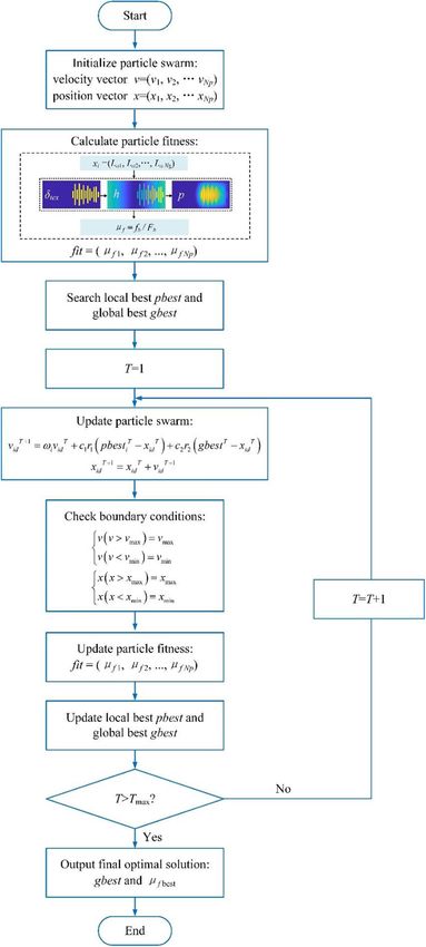
2                                      X. Zhang et al.: Mechanics & Industry 22, 1 (2021)

gradual method for increasing Fourier series orders. To
obtain minimum friction coefficients of a journal bearing
and bearing slider, Zhang et al. [19,20] adopted GA to
optimize the coverage area of circular dimples. In their
researches, bearing surface is divided into certain numbers
of grids and the dimple in each grid center existing or not is
marked with 1 or 0, respectively. Then GA is used to evolve
the solution process and the final optimal coverage area is
like a semi-elliptical shape. Sinanoglu et al. [21] experi-
mentally and theoretically researched the influences of
shaft surface textures on film pressure and consequently on
                                                                               Fig. 1. A textured journal bearing.
load by proposed neural network. The shaft surfaces
included two types: trapezoidal and saw surfaces. Their
results showed the shaft with trapezoidal surface has larger
load carrying capacity than the shaft with saw surface.           3 Lubrication model
    The above literatures have showed the genetic algo-
rithm and neural network can be successfully employed in          3.1 Film thickness
surface texture design for journal bearings, while the PSO
algorithm may provide a more convenient way for this              As illustrated in Figure 1, film thickness h can be obtained
issue. Particle swarm optimization (PSO), presented by            by equation (2)
Eberhart and Kennedy [22,23] in 1995, is an optimization
method motivated by behaviors of bird flocking/roosting.                          h ¼ c½1 þ e cos ðu  ’Þ þ dtex          ð2Þ
In view of this algorithm, the individual members establish
a social network and can benefit from previous experiences         where c is the radial clearance, e the eccentricity ratio
and discoveries of the other members. PSO algorithm is            (e = e/c, e eccentricity), ’ the attitude angle, dtex the
easier to implement because the swarm are updated only by         clearance added by groove textures.
updating the particle velocity and position vectors, which
shows this approach has great potentials for use in the           3.2 Reynolds equation
designs for air foil bearing [24], rolling element bearing [25]
and magnetorheological (MR) bearing [26].                         The Reynolds equation under steady operating conditions
    Although PSO has been used in some previous                   is shown below [19]
researches, few scholars adopted this algorithm to optimize                    3
surface textures for a journal bearing. The novelty of this                 ∂   h ∂p       ∂ h3 ∂p        U ∂h
                                                                                    ⋅   þ          ⋅    ¼             ð3Þ
study is to optimize the distributions of groove textures in a             ∂x 12m ∂x      ∂y 12m ∂y        2 ∂x
journal bearing to reduce its friction coefficient by PSO
algorithm. The effects of eccentricity ratios and rotary          where U is the relative velocity, m the oil viscosity, p the
speeds on optimal distributions of groove textures are also       film pressure. For the journal bearing, U = Rv, R is the
discussed. Overall, the optimization idea in this study may       journal radius, v its angular velocity. The employed
be helpful for journal bearings to improve their tribological     Reynolds equation can be obtained by replacing the
performance.                                                      variable x with Ru in equation (3), as expressed in
                                                                  equation (4)
2 Description of a journal bearing with
groove textures                                                             1 ∂ h3 ∂p          ∂ h3 ∂p           ∂h
                                                                                      ⋅    þ         ⋅     ¼ 6v            ð4Þ
                                                                           R2 ∂u m ∂u         ∂y m ∂y            ∂u
Generally, textures located in convergent area is more
favorable for improving tribological performance [19]. In
this study, the convergent area is covered with groove
textures, as illustrated in Figure 1. A detailed description of   3.3 Load carrying capacity
groove textures is illustrated in Figure 2. The detailed          Integrate film pressure p over whole the computation
parameters of a journal bearing and groove textures are           domain, then load carrying capacity Fb is obtained, as
given in Tables 1 and 2. Note the oil is assumed as               expressed in equations (5) and (6)
isoviscous incompressible fluid.
    As Table 2 shows, us, ue, Lc, Lg and dg are fixed, while La                 8         Z B Z 2p
                                                                               >
                                                                               >
                                                                               >
                                                                               < F x ¼ þ 0 0 pR sin ududy
is variable from 0 to 34 mm. Note the groove length 0 mm                       >
means there is no groove and groove length 34 mm means
                                                                                         Z B Z 2p                    ð5Þ
the longest groove is slightly shorter than bearing width.                     >
                                                                               >
                                                                               >F ¼
                                                                               >                  pR cos ududy
The groove numbers Ng is
                     "                       #                                 : z
                                                                                            0        0
                       Rðue  us Þ  ðp=180Þ
              Ng ¼                           þ1          ð1Þ
                               Lc þ Lg                                                          qffiffiffiffiffiffiffiffiffiffiffiffiffiffiffiffiffiffiffiffiffi
    According to the above geometric parameters, Ng = 13.                              Fb ¼      F x2 þ F z2              ð6Þ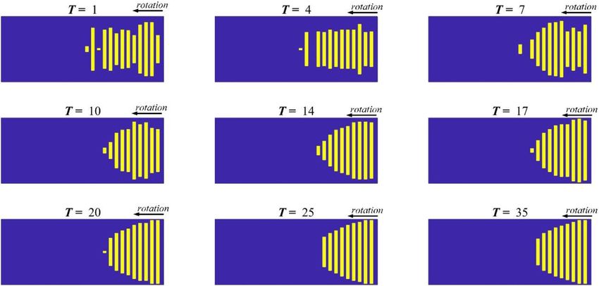
X. Zhang et al.: Mechanics & Industry 22, 1 (2021)                                  3

                                              Fig. 2. Groove textures in bearing inner surface.

Table 1. Detailed parameters of a journal bearing.

Parameters                                           Values                    Parameters                               Values
Oil viscosity m (Pa · s)                             0.088                     Radial clearance c (mm)                  0.057
Bearing diameter D (mm)                              35                        Oil hole diameter dh (mm)                5
Bearing width B (mm)                                 35                        Rotary speed N (rpm)                     2000

Table 2. Geometric parameters of groove textures.

Parameters                                    Interpretations                                                           Values
us                                            Start position of the first groove (°)                                     10
ue                                            Start position of the last groove (°)                                     180
La                                            Groove length in axial direction (mm)                                     0–34
Lc                                            Groove width in circumferential direction (mm)                            2
Lg                                            Groove gap in circumferential direction (mm)                              2
dg                                            Groove depth (mm)                                                         10

3.4 Friction coefficient                                                   Then the friction coefficient mf can be calculated by
                                                                       equation (8)
The friction fb arising from the shearing effect of oil can be                               mf ¼ f b =F b                  ð8Þ
calculated by equation (7)

                   Z       Z                                         3.5 Numerical validation
                               2p
                       B
                                     mU    h ∂p
            fb ¼                        þ         Rdudy          ð7Þ   In numerical solution, the bearing inner surface is
                   0       0          h   2R ∂u                        divided into rectangular grids, and nodes numbers in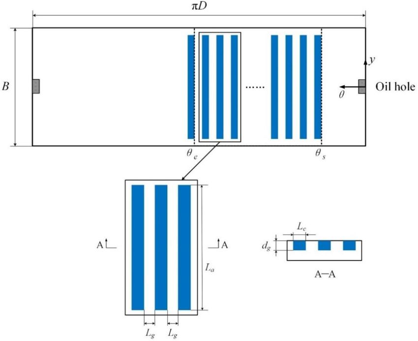
4                                          X. Zhang et al.: Mechanics & Industry 22, 1 (2021)

Table 3. Comparisons of Sommerfeld numbers with Pinkus and Sternlicht [27].

                            This study                       Pinkus and Sternlicht [27]                      Relative deviation (%)
                                                             (B/D = 1)
e   =   0.1                 1.334                            1.350                                           1.185
e   =   0.2                 0.635                            0.632                                           0.475
e   =   0.3                 0.391                            0.382                                           2.356
e   =   0.4                 0.262                            0.261                                           0.383
e   =   0.5                 0.179                            0.179                                           0

circumferential and axial directions are nu and ny,                    where i is the particle number, i = 1, 2, 3, …, 30; d the Ng
respectively. The equation (4) is discretized by finite                 dimensions, d = 1, 2, 3, …, Ng; vi the inertia weight.
difference method, and the pressure is solved by over-                 According to Shi and Eberhart [28], PSO has the best
relaxation iterative method. The rupture area of oil film is            chance to find global optimum if vi satisfies 0.9  vi  1.2,
determined by Reynolds boundary conditions, and the                    here vi = 0.9; c1 and c2 the learning factors, c1 = c2 = 2 [28];
pressure in oil hole and both ends of bearing are zero. The            r1 and r2 the random numbers between 0 and 1 [28]; pbestiT
pressure convergence criteria ep is 105, and the solution             the local best; gbestT the global best; T the index of
process will be terminated if |DPi|/|Pi | vmax Þ ¼ vmax
analysis. The Sommerfeld number S are calculated based                                                                            ð11Þ
on the researched journal bearing, and the results are                                        vðv < vmin Þ ¼ vmin
compared with Pinkus and Sternlicht [27], as illustrated in
Table 3. It can be seen the Sommerfeld numbers calculated                                 (
                                                                                              xðx > xmax Þ ¼ xmax
by this study agree well with literature’s results, which                                                                         ð12Þ
shows good accuracy of this model.                                                            xðx < xmin Þ ¼ xmin

4 Particle swarm optimization algorithm                                where vmax = 4, vmin = 4. The velocity range [4, 4] is
                                                                       determined through a multitude of trials, which can help
General researches consider the grooves have an equal                  the particles avoid flying past good solution areas or
length for convenience. In the authors’ opinion, grooves               trapping into local optimal solution [29]. xmax and xmin are
with unequal lengths may bring more benefits. In this                   the maximum and minimum of groove lengths, xmax = 34 mm,
study, groove lengths are optimized by PSO algorithm.                  and xmin = 0 mm.
Figure 3 shows the computational process of PSO, which                     (4-b) Update the particle fitness according to new swarm.
includes following steps:                                                  (4-c) Update the local best pbest and global best gbest.
     (1) Initialize a particle swarm with 30 particles to be               (4-d) Exit the loop if T is greater than Tmax = 100;
randomly generated. The swarm size Np = 30 is selected                 Otherwise, return to (4-a) and repeat (4-a)–(4-d).
from 20, 30, 50 and 70, which can balance the contradiction                (5) Output the final optimal solution: gbest and mf best.
between computing time and population diversity. The
dimension of each particle is Ng, and the particle elements
are random groove lengths.                                             5 Results and discussions
     (2) Calculate the particle fitness according to initial
swarm. The friction coefficient mf is adopted as the fitness             The mesh refinement is firstly performed based on smooth
function.                                                              bearing. The friction coefficients mf under e = 0.2, 0.4, ’ = 0
     (3) Search the local best pbest and global best gbest.            of different mesh schemes nuny are shown in Figure 4,
     (4) Perform the iterative calculation. This step is the           which shows mf tends to stabilize gradually with denser
key of PSO algorithm, which can be subdivided into                     grids. Considering the accuracy and solving speed,
following substeps:                                                    551  177 mesh is adopted. In this scheme, the single grid
     (4-a) Update the particle velocity vector vid and                 is approximately to a square with 0.2 mm side length.
position vector xid
                                                                   5.1 Optimal distributions of groove textures under
vid T þ1 ¼ vi vid T þ c1 r1 pbesti T xid T þ c2 r2 gbestT  xid T     fixed eccentricity ratio
                                                                ð9Þ
                                                                       Based on Section 4, the changes of mfbest under e = 0.1, ’ = 0
                                                                       is illustrated in Figure 5. With increasing of generations
                     xid T þ1 ¼ xid T þ vid T þ1               ð10Þ    from 1 to 30, the mfbest shows a decreasing trend, which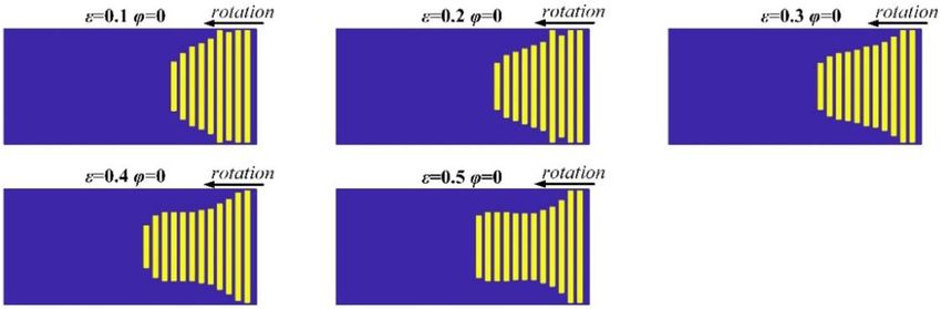
X. Zhang et al.: Mechanics & Industry 22, 1 (2021) 5
distribution with random groove lengths, and then
gradually evolves to the final optimal distribution, whose
shape is like a trapezium.
To further explain the optimal distribution of groove
textures, the distribution of groove textures with an equal
length 34 mm is given as reference, and the groove number
in reference is same with it in the optimal one, as illustrated
in Figure 7.
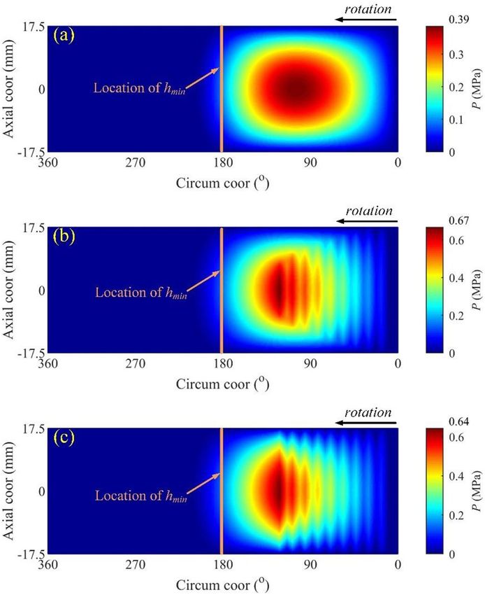
Figure 8 shows the pressure distributions of smooth,
optimal textured and reference textured bearings under
e = 0.1, ’ = 0, and Figure 9 illustrates the comparisons of
load carrying capacity, friction, and friction coefficients
between three bearings. It can be seen the optimal and
reference textured bearings generate greater film pressures
than smooth bearing due to local hydrodynamic pressures
generated by grooves, which yield larger load carrying
capacities. Moreover, the optimal textured bearing also
generates greater pressure and larger load carrying
capacity than referenced textured bearing. It can be
explained that for the reference textured bearing, grooves
with an equal length can destroy the pressure generations
at upper and lower boundaries, that is, grooves located at
upper and lower boundaries can suppress the pressure
generation here. In contrast, gradually shortened grooves
in optimal textured bearing reduce this pressure suppres-
sion, which yield greater pressure and load carrying
capacity. Meanwhile, the frictions among three bearings
are almost same. Hence, based on equation (8), the optimal
textured bearing has a minimum friction coefficient, then
followed by the reference textured and smooth bearings,
respectively.
5.2 Effects of eccentricity ratios on optimal
distributions of groove textures
In Section 5.1, the eccentricity ratio e is 0.1. In this section,
the effects of eccentricity ratios (e = 0.1–0.5) on optimal
distributions of groove textures are discussed and shown in
Figure 10. It can be seen this optimal distribution is still
like a trapezium with increasing of e, but it becomes
slenderer. The reduction of friction coefficient between
smooth and optimal textured bearings dmf is defined in
equation (13)
mf smooth mf optimal
dmf ¼ 100% ð13Þ
mf smooth
The friction coefficients mf and reductions dmf are also
given. As illustrated in Figure 11, with increasing of e, dmf
gradually decreases from approximately 30% to 8%, which
Fig. 3. Computational process of PSO algorithm. indicates the reductions of friction coefficients by optimal
groove textures are more significant under lower eccentric-
ity ratios.
indicates the swarm is in continuing evolution. When the 5.3 Effects of rotary speeds on optimal distributions
generation is beyond 30, mf best maintains a constant value of groove textures
0.0607, which indicates the swarm has been in a stable
state. The progressive changes of distributions under In Sections 5.1 and 5.2, the rotary speed is 2000 rpm. In
e = 0.1, ’ = 0 are shown in Figure 6. It starts from a this section, the effects of rotary speeds on optimal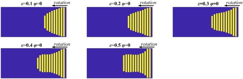
6                     X. Zhang et al.: Mechanics & Industry 22, 1 (2021)

    Fig. 4. Friction coefficients mf of different mesh schemes under (a) e = 0.2, (b) e = 0.4.

             Fig. 5. The mf   best   varying with the generations under e = 0.1, ’ = 0.

            Fig. 6. The progressive changes of distributions under e = 0.1, ’ = 0.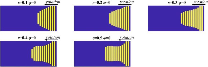
X. Zhang et al.: Mechanics & Industry 22, 1 (2021)                                            7

                                Fig. 7. The optimal and reference distributions of groove textures.

Fig. 8. Pressure distributions under e = 0.1, ’ = 0 of (a) smooth bearing, (b) optimal textured bearing, (c) reference textured bearing.

Fig. 9. Comparisons of (a) load carrying capacity, (b) friction, (c) friction coefficient, between smooth, optimal textured, and
reference textured bearings under e = 0.1, ’ = 0.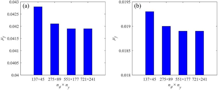
8                                     X. Zhang et al.: Mechanics & Industry 22, 1 (2021)

                         Fig. 10. The optimal groove textures under e = 0.1–0.5, ’ = 0, N = 2000 rpm.

                                 Fig. 11. mf and dmf under e = 0.1–0.5, ’ = 0, N = 2000 rpm.

                         Fig. 12. The optimal groove textures under e = 0.1–0.5, ’ = 0, N = 1000 rpm.

distributions of groove textures and dmf are discussed. The     6 Conclusions
speeds 500, 1000, 1500, 2500 and 3000 rpm are considered.
As the results of these cases are similar, only the 1000 and    This study focuses on optimizing the distributions of
3000 rpm cases are given, as illustrated in Figures 12–15. It   groove textures in a journal bearing to reduce its friction
can be seen the results in Figures 12–15 are similar with       coefficient using PSO algorithm. Some conclusions are
these in Figures 10 and 11, which indicates the optimal         summarized below:
distributions of groove textures and trends of dmf are          – For the researched journal bearing, the optimal
consistent under different rotary speeds.                         distribution of groove textures is like a trapezium.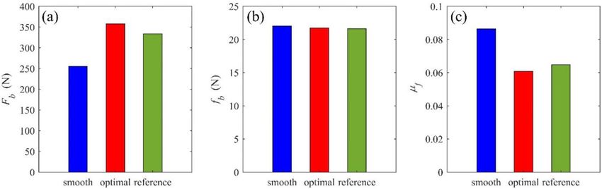
X. Zhang et al.: Mechanics & Industry 22, 1 (2021)                               9

                              Fig. 13. mf and dmf under e = 0.1–0.5, ’ = 0, N = 1000 rpm.

                      Fig. 14. The optimal groove textures under e = 0.1–0.5, ’ = 0, N = 3000 rpm.

                              Fig. 15. mf and dmf under e = 0.1–0.5, ’ = 0, N = 3000 rpm.

This distribution can reduce the pressure suppression        – With increasing of eccentricity ratios (e = 0.1–0.5),
caused by grooves located at upper and lower boundaries,       the optimal distributions of groove textures
which yield greater film pressure and load carrying             become slenderer, and the reductions of friction
capacity. This is the main reason to reduce the friction       coefficients by optimal groove textures are more
coefficient.                                                    significant under lower eccentricity ratios.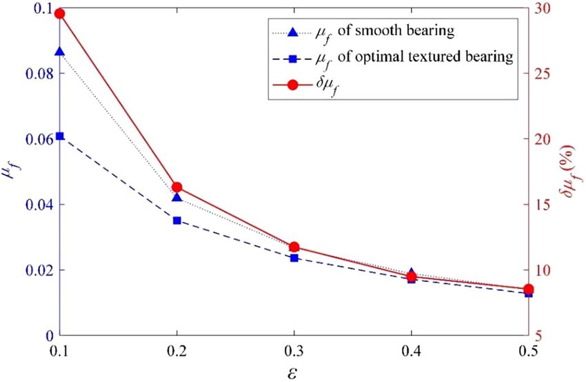
10                                     X. Zhang et al.: Mechanics & Industry 22, 1 (2021)

– The optimal distributions and reductions of friction          This study is supported by National Natural Science Foundation
  coefficients are similar under different rotary speeds,        of China (Grant No. 51809057).
  which indicate the conclusions of this optimization have
  certain universality.
    In future work, the authors will research the optimal       References
groove textures for the journal bearing by choosing other
optimization variables (such as groove depth and width) or       [1] D. Gropper, L. Wang, T.J. Harvey, Hydrodynamic lubrica-
other optimization goal (such as temperature rise), and the          tion of textured surfaces: a review of modeling techniques
corresponding experiments will be performed to verify these          and key findings, Tribology International 94, 509–529 (2016)
                                                                 [2] X.H. Shen, Y.L. Shi, J.H. Zhang, Q.J. Zhang, G.C. Tao,
studies.
                                                                     L.J. Bai, Effect of process parameters on micro-textured
                                                                     surface generation in feed direction vibration assisted
                                                                     milling, International Journal of Mechanical Sciences 167,
Nomenclature                                                         105267 (2020)
                                                                 [3] K. Kanda, S. Tazawa, T. Urano, S. Kobayashi, K. Adachi,
D            Bearing diameter                                        The possibility of both low friction and low leakage by
B            Bearing width                                           surface texture of mechanical seals in blood, Tribology
dh           Oil hole diameter                                       Letters 68, 1–11 (2020)
N            Rotary speed                                        [4] S. Ding, S. Bai, Thermoelastohydrodynamic behaviour of
us           Start position of textured region                       inclined-ellipse dimpled gas face seals, Science China
ue           End position of textured region                         Technological Sciences 60, 529–537 (2016)
La           Groove length in axial direction                    [5] S. Ye, H. Tang, Y. Ren, J. Xiang, Study on the load-carrying
Lc           Groove width in circumferential direction               capacity of surface textured slipper bearing of axial piston
Lg           Groove gap in circumferential direction                 pump, Applied Mathematical Modelling 77, 554–584 (2020)
dg           Groove depth                                        [6] D.G. Fouflias, A.G. Charitopoulos, C.I. Papadopoulos,
Ng           Groove numbers                                          L. Kaiktsis, Thermohydrodynamic analysis and tribological
dtex         Variation clearance caused by groove textures           optimization of a curved pocket thrust bearing, Tribology
                                                                     International 110, 291–306 (2017)
h            Film thickness
                                                                 [7] C. Shen, M.M. Khonsari, Tribological and Sealing Perfor-
c            Radial clearance
                                                                     mance of Laser Pocketed Piston Rings in a Diesel Engine,
e            Eccentricity ratio                                      Tribology Letters 64, 1–9 (2016)
’            Attitude angle                                      [8] D. Nečas, H. Usami, T. Niimi, Y. Sawae, I. Krupka, M. Hartl,
R            Journal radius                                          Running-in friction of hip joint replacements can be
m            Oil viscosity                                           significantly reduced: the effect of surface-textured acetabu-
p            Film pressure                                           lar cup, Friction 8, 1137–1152 (2020)
v            Angular velocity of journal                         [9] H. Kasem, H. Shriki, L. Ganon, M. Mizrahi, K. Abd-Rbo,
Fb           Load carrying capacity                                  A.J. Domb, Rubber plunger surface texturing for friction
fb           Friction                                                reduction in medical syringes, Friction 7, 351–358 (2018)
mf           Friction coefficient                                [10] A.B. Shinde, P.M. Pawar, Multi-objective optimization of
vs           Overrelaxation factor                                   surface textured journal bearing by Taguchi based Grey
ep           Allowable precision for the solution of pressure        relational analysis, Tribology International 114, 349–357
Np           Particle swarm size                                     (2017)
vid          Particle velocity vector                           [11] S. Kango, R.K. Sharma, R.K. Pandey, Comparative analysis
xid          Particle position vector                                of textured and grooved hydrodynamic journal bearing,
vi           Inertia weight                                          Proceedings of the Institution of Mechanical Engineers,
c 1, c 2     Learning factors                                        Part J: Journal of Engineering Tribology 228, 82–95 (2013)
r1 , r2      Random numbers between 0 and 1                     [12] B. Manser, I. Belaidi, A. Hamrani, S. Khelladi, F. Bakir,
pbest        The local best                                          Performance of hydrodynamic journal bearing under the
gbest        The global best                                         combined influence of textured surface and journal misalign-
                                                                     ment: a numerical survey, Comptes Rendus Mécanique 347,
vmin         Minimum velocity
                                                                     141–165 (2019)
vmax         Maximum values
                                                                [13] R. Yu, W. Chen, P. Li, The analysis of elastohydrodynamic
xmin         Minimum groove length                                   lubrication in the textured journal bearing, Proceedings of
xmax         Maximum groove length                                   the Institution of Mechanical Engineers, Part J: Journal of
T            The index of generations                                Engineering Tribology 230, 1197–1208 (2016)
Tmax         Maximum index of generations                       [14] Q. Lin, Q. Bao, K. Li, M.M. Khonsari, H. Zhao, An
mf best      The minimum mf in particle swarm during each            investigation into the transient behavior of journal bearing
             generation                                              with surface texture based on fluid-structure interaction
mf smooth    Friction coefficient of smooth bearing                   approach, Tribology International 118, 246–255 (2018)
mf optimal   Friction coefficient of optimal textured bearing    [15] N. Tala-Ighil, M. Fillon, P. Maspeyrot, Effect of textured
dmf          The reduction of friction coefficients between           area on the performances of a hydrodynamic journal bearing,
             smooth and optimal textured bearings                    Tribology International 44, 211–219 (2011)
X. Zhang et al.: Mechanics & Industry 22, 1 (2021) 11
[16] N. Tala-Ighil, M. Fillon, A numerical investigation of both [22] J. Kennedy, R. Eberhart, Particle swarm optimization,
thermal and texturing surface effects on the journal bearings Proceedings of IEEE International Conference on Neural
static characteristics, Tribology International 90, 228–239 Networks 4, 1942–1948 (1995)
(2015) [23] R. Eberhart, J. Kennedy, A New Optimizer Using Particle
[17] A.B. Shinde, P.M. Pawar, Effect of partial grooving on the Swarm Theory, Proceedings of the Sixth International
performance of hydrodynamic journal bearing, Industrial Symposium on Micro Machine and Human Science (1995)
Lubrication and Tribology 69, 574–584 (2017) [24] N. Wang, H.-C. Huang, C.-R. Hsu, Parallel optimum design
[18] X. Pang, J. Chen, S.H. Hussain, Numeric and experimental of foil bearing using particle swarm optimization method,
study of generalized geometrical design of a hydrodynamic Tribology Transactions 56, 453–460 (2013)
journal bearing based on the general film thickness equation, [25] S. Panda, S.N. Panda, P. Nanda, D. Mishra, Comparative
Journal of Mechanical Science and Technology 26, study on optimum design of rolling element bearing,
3149–3158 (2012) Tribology International 92, 595–604 (2015)
[19] H. Zhang, M. Hafezi, G. Dong, Y. Liu, A design of coverage [26] R. Li, P.F. Du, S.M. Zhou, T.X. Zheng, Parameter
area for textured surface of sliding journal bearing based on optimization experiment of magnetorheological bearing,
genetic algorithm, Journal of Tribology 140, 061702 Applied Mechanics and Materials 457–458, 597–601 (2013)
(2018) [27] O. Pinkus, B. Sternlicht, Theory of hydrodynamic lubrica-
[20] H. Zhang, Y. Liu, M. Hua, D.-y. Zhang, L.-g. Qin, G.-n. Dong, tion, McGraw-Hill, New York (1961)
An optimization research on the coverage of micro-textures [28] Y. Shi, R. Eberhart, A Modified Particle Swarm Optimizer,
arranged on bearing sliders, Tribology International 128, 1998 IEEE International Conference on Evolutionary
231–239 (2018) Computation Proceedings, IEEE World Congress on
[21] C. Sinanoğlu, F. Nair, M.B. Karamış, Effects of shaft surface Computational Intelligence (1998)
texture on journal bearing pressure distribution, Journal of [29] Y. Shi, Particle Swarm Optimization, IEEE Connections
Materials Processing Technology 168, 344–353 (2005) 8–13 (2004)
Cite this article as: X. Zhang, C. Liu, B. Zhao, An optimization research on groove textures of a journal bearing using particle
swarm optimization algorithm, Mechanics & Industry 22, 1 (2021)You can also read