Understanding and tuning the Injection Pump of Land Rover Tdi Engines
←
→
Page content transcription
If your browser does not render page correctly, please read the page content below
Land Rover Tdi Injection Pump Tuning
Understanding and tuning the Injection Pump of
Land Rover Tdi Engines
The Disclaimer:
This article is presented for the interest of readers from information gathered from various sources
including Bosch technical literature and the internet. The author makes no claims to be an expert on
diesel engine tuning, nor for the accuracy of this information. The author cannot accept any
responsibility for the consequences of actions taken by others using any or all of this information.
Make sure you fully understand the information and accept the consequences before making any use
of it.
There's no such thing as a free lunch - if you modify your engine to give better performance it will be
working harder and components may wear out sooner than otherwise. If you get things wrong it may
well ‘wear out’ a lot sooner…
The Basics
The Land Rover 200Tdi & 300Tdi engines of the late ‘80s to late ‘90s utilise the Robert
Bosch VE-type diesel injection pump. Like all diesel engines, the purpose of the injection
pump is to deliver a precisely-metered charge of diesel fuel to each cylinder injector, in the
firing order of the engine. The Bosch VE injection pump uses a single pump plunger to
produce these high-pressure fuel charges. The pump mechanism includes a distributor
section to direct each successive charge to the appropriate cylinder injector, in the required
order.
The actual fuel charge delivered to the injectors is proportional to the pump stroke. The
effective stroke is continuously adjusted according to the throttle position and the engine
speed (rpm). This function is performed by the mechanical fly-weight governor mechanism
within the pump. In a naturally-aspirated diesel (or assuming the boost pressure remains
constant in a turbo-charged engine), the governor will adjust the pump stroke to try to
maintain a particular engine rpm at any given throttle setting. That is, unlike a carburetted
petrol engine where the throttle directly alters the quantity of air/fuel mixture drawn into the
cylinders, in a diesel the throttle merely adjusts the 'rpm setpoint' of the engine.
At a fixed throttle position, as the load changes (e.g. the road rises or falls slightly) the fly-
weight governor will increase or decrease the fuel charge to attempt to keep the engine rpm
constant, within limits of course. A bit like a very basic 'cruise control'. In practice, the
engine rpm and hence the vehicle speed will vary quite a bit as the load changes, despite the
best efforts of the governor. [If you want to get technical, this is because a fly-weight governor is a
‘proportional action’ type of controller and will settle at a different ‘steady state’ point for each different
load on the engine.]
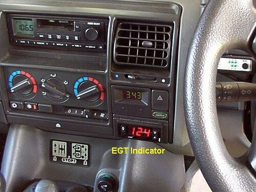
Boost Compensation
Now, the description above stated "assuming the
boost pressure remains constant in a turbo-
charged engine..." Of course, it rarely remains
constant for very long. For this reason, the
Bosch VE injection pump used on 200Tdi and
non-EDC1 300Tdi LR engines has a boost
compensator (also called a manifold-pressure
compensator or 'aneroid') to enable it to further
control fuel delivery in proportion to the boost
1
Electronic Diesel Control, fitted to some late model
300Tdi engines
Figure 1
Tdi VE Adjust Rev.2.doc Page 1 of 8 Copyright © Ian Petersen 2003-2004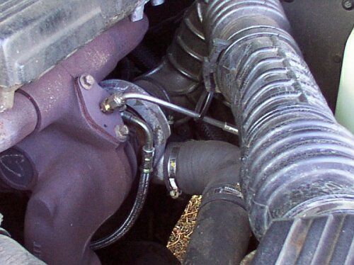
Land Rover Tdi Injection Pump Tuning

pressure at the turbo-charger air outlet. This is necessary as the mass of air in the cylinders
varies greatly as the boost pressure increases from zero to full boost. At low boost
pressures, the cylinder air mass is much smaller and is not sufficient to fully combust the
maximum fuel charge. Therefore, the boost compensator’s job is to reduce the maximum
fuel charge when the boost pressure is less than maximum. A tube from the turbo air outlet
to the diaphragm chamber on the top of the boost compensator transmits the pressure
signal.
In order to consistently achieve low smoke emissions on every vehicle leaving the assembly
line, it seems the 'standard' settings of the boost compensator are very conservative. That
is, they severely restrict the fuel delivery at less than full boost in order to ensure low smoke
emissions. This seems to result in the legendary off-idle sluggishness of the Tdi engines.
By carefully adjusting and optimising the boost compensator settings for a particular engine,
significant improvements can be had in off-boost and low to mid-range rpm performance,
without excessive smoke emissions. [By the way, if you are making black smoke you are just
wasting fuel, not making more power. The object is to have the engine just on the brink of making
smoke when under full throttle, at any combination of rpm and boost pressure.]
                                               Boost compensation works by automatically
                                               adjusting the position of a pump Stroke
                                               Limiting Pin within the pump. This pin lies
                                               horizontally through the pump body and it's end
                                               is visible at the bottom of the boost
                                               compensator well.      When in the rearward
                                               position (away from the front or drive end of the
                                               pump) the pump delivers it's 'high boost' fuel
                                               charges to the injectors, as defined by the
                                               internal design of the pump. When this pin is
                                               pushed forward, the fuel charge, for any given
                                               rpm and throttle setting, is reduced to
                                               compensate for the reduced air charge to the
                     Figure 2                  cylinders when the boost pressure is lower.
The stroke limiting pin is positioned by the up
and down movement of an eccentric Control
Cone attached to a diaphragm which senses
boost pressure. When there is effectively no
boost,    such      as     when       idling,   the
diaphragm/control cone is held in the fully up
position by its spring and sits against the stop
screw in the top cover. In this position, the
limiting pin is bearing against the thickest
(bottom) part of the control cone. Therefore it is
pushed forward to it's most restrictive position.
As boost pressure increases, the pressure
above the diaphragm begins to overcome the
spring force and the control cone is pushed                    Figure 3
downwards. The stroke limiting pin now bears
against a narrower part of the control cone and is allowed to move backward slightly,
allowing increased fuel delivery. Eventually, when maximum boost is achieved, the
diaphragm/control cone no longer moves any further downward, the limiting pin ceases to
move further rearward and fuel delivery is solely determined by the governor, with no
additional restriction from the boost compensator.

Tdi VE Adjust Rev.2.doc                     Page 2 of 8            Copyright © Ian Petersen 2003-2004
Land Rover Tdi Injection Pump Tuning

Boost Compensator Adjustments
There are three adjustments available in the VE pump boost compensator:
1. The rotational position of the eccentric control cone at the bottom of the diaphragm/cone
   assembly, adjusted by rotating the assembly. (See Fig. 3)
2. The diaphragm spring pre-load, adjusted by rotating the 'starwheel' on the lower spring
   seat (See Fig. 2),
3. The diaphragm/cone rest position, adjusted using the Torx stop screw and locknut in the
   diaphragm cover (See Fig. 4).
The following sections shall examine each of these adjustments in detail and explain their
effect on fuel charge delivery, with reference to the appropriate photographs and diagrams.

1. Diaphragm rotational position
    1.1. As shown in Figure 3, the control cone
         is mounted eccentrically on the
         diaphragm shaft. Therefore, as the
         diaphragm/cone assembly is rotated
         through 180 °, the side of the cone
         which bears against the stroke limiting
         pin will change from the ‘most forward’
         to the ‘most rearward’ This is the
         fundamental       adjustment      which
         determines the overall range of stroke
         limit pin movement.
    1.2. As shown in Figure 4, the position of
         the diaphragm/cone assembly is                          Figure 4
         determined by the ‘centre punch’
         reference mark near the edge of the central steel plate of the diaphragm. It is
         essential to note the original position of this reference mark when the
         diaphragm cover is first removed.
    1.3. The eccentric control cone in my 300Tdi is marked “13H”. Presumably there are a
         range of different pins available to characterise the VE pump for different engine
         applications.
    1.4. For the following description, the position of the diaphragm is described in terms of
         degrees of rotation from the ‘maximum’ position. This is defined as that which
         orients the control cone to its ‘most rearward’ position. That is, the position which
         allows the stroke limit pin to travel most rearward. Therefore the ‘maximum’ position
         corresponds to the maximum fuel position. In the case of my assembly this
         coincided with the reference mark being at the ‘twelve o’clock’ position (to the
         top/high/tappet cover side, as shown in Figure 4 above). I do not know if this is
         always the case.
    1.5. Also for this description, the travel of the stroke limit pin is defined as starting from
         the ‘most rearward’ position able to be achieved (maximum fuel position). That is,
         0.0mm of travel is achieved when the diaphragm is positioned so that the control
         cone is ‘most rearward’ and the diaphragm is in the fully depressed position. The pin
         travel may be thought of as ‘millimetres of restriction’, when 0.0mm means zero
         restriction of fuel delivery.
    1.6. The chart, Figure 5, shows the approximate relationships between the diaphragm
         rotational position and it’s effect on stroke limit pin position. [The dimensions listed are
         approximations to the nearest millimetre from measurements taken from my 13H assembly
         and should not be taken as precise nor completely accurate.]

Tdi VE Adjust Rev.2.doc                      Page 3 of 8              Copyright © Ian Petersen 2003-2004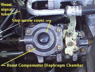
Land Rover Tdi Injection Pump Tuning

    1.7. The diaphragm/control cone assembly has a total vertical travel of about 10.0mm. At
         the bottom of the effective travel, it’s diameter where the stroke limit pin bears is
         about 9.0mm. At the top of effective travel it’s diameter is about 5.0mm. It is
         mounted about 1.0mm off-centre.

                                                                     B osch VE Inje ction Pump - B oost C ompe nsator

                                                        6.0

                                                        5.0
        Stroke Limit Pin Travel

                                                                                                                                       D iaphragm R otatio n
                                  (mm of restriction)

                                                                                                                                       0 D eg (Max. Pos ition)
                                                        4.0
                                                                                                                                       D iaphragm R otatio n
                                                                                                                                       90 D eg
                                                        3.0
                                                                                                                                       D iaphragm R otatio n
                                                        2.0                                                                            180 D e g

                                                        1.0

                                                        0.0
                                                              0.0   1 .0   2.0   3.0   4.0   5.0   6 .0   7.0   8.0   9.0 10.0

                                                                           D iaphragm D e pre ssion (mm)

                                                                                                   Figure 5
Therefore, as shown in Figure 5, the stroke limit pin will move about 4.0mm as the
diaphragm/control cone moves downward over it’s 10.0mm of travel. This 4.0mm of travel
may be varied from the ‘0.0 to 4.0mm’ range to the ‘1.0 to 5.0mm’ range by rotating the
diaphragm up to 180 degrees from the ‘maximum’ position. As the diaphragm/control cone is
symmetrical, it doesn’t matter which way it is rotated from the ‘maximum’ position. Also note
that 180 degrees of rotation (½ turn) represents the full range of adjustment available.

2. Diaphragm Spring Pre-Load
    2.1. Figure 2 shows the ‘starwheel’ which adjusts the spring pre-load. My spring, marked
         “7 712”, appears to be a linear coil spring. Therefore I have assumed a linear
         relationship between boost pressure on the diaphragm and diaphragm/control cone
         depression, shown in Figure 6.
    2.2. To simplify the chart, I have also assumed the maximum boost is exactly 1.0 bar and
         that there is some spring pre-load position which results in exactly 10mm of
         depression at 1.0 bar.
                        Again, the intention is not to present absolutely accurate measurements, rather to
                        indicate the relationship between the adjustments and the behaviour of the boost
                        compensator.
    2.3. The ‘starwheel’ is the lower mount for the spring and has a right-hand thread.
         Turning it clockwise (CW) lowers the spring mount and reduces pre-load. Turning it
         counter-clockwise (CCW) increases pre-load. It is held in the set position by two
         spring-loaded ‘fingers’ which engage the ‘teeth’ on the outer edge at about the 1
         o’clock and 5 o’clock positions. To adjust the ‘starwheel’, the fingers need to be held
         away from the wheel with, say, two small screwdrivers. Again, it is essential to
         note the original position of the ‘starwheel’ before any adjustments are made.
         The ‘starwheel’ should be marked with scribe mark or permanent marker at the 12

Tdi VE Adjust Rev.2.doc                                                                        Page 4 of 8                   Copyright © Ian Petersen 2003-2004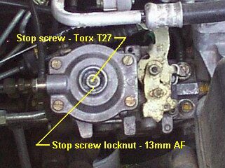
Land Rover Tdi Injection Pump Tuning

               o’clock position so that any adjustments can be referenced to the original position.

                                             B osch V E In jection P um p - B o ost C om pe nsato r

                                    10.0

                                     9.0
        Diaphragm Depression (mm)

                                     8.0                                                           S pring P reload (m m ) 0.0

                                     7.0                                                           S pring P reload (m m ) 0.5
                                     6.0
                                                                                                   S pring P reload (m m ) 1.0
                                     5.0
                                                                                                   S top S c rew
                                     4.0                                                           (m m ) 0.5
                                     3.0                                                           S top S c rew
                                                                                                   (m m ) 1.0
                                     2.0

                                     1.0

                                     0.0
                                       0.0    0.2      0.4     0.6     0.8         1.0   1.2
                                                    B o o st P ressu re (b ar)

                                                                        Figure 6

    2.4. Figure 6 shows the pre-load in millimetres. I have not measured the pitch of the
         ‘starwheel’ thread to relate turns with millimetres of vertical travel of the spring
         mount. Again however, the object is to show the effect of increasing/decreasing pre-
         load on fuel delivery. As shown in Figure 6, increasing pre-load means a higher
         boost pressure will be needed to depress the diaphragm to a certain point and hence
         to allow the stroke limit pin to move rearward to a particular point. Conversely for
         reducing pre-load.

3. Diaphragm rest position
    3.1. Figure 7 shows the stop screw with Torx
         27 head and locknut. The action of the
         stop screw is also shown in Figure 6. It
         sets a minimum diaphragm depression
         regardless of boost pressure (or the
         lack thereof). In conjunction with the
         other adjustments, it sets the fuel
         delivery limit when there is no boost,
         such as when first moving off from rest
         at low rpm.
    3.2. The stop screw is accessed by
         removing the light steel cap pressed
         into the recess on top of the diaphragm                      Figure 7
         cover.     This can be removed by
         carefully prising it out with a rocking motion, using two fine screwdrivers. Figure 1
         shows the original cap replaced with a 22mm chair leg plug, after adjustment. This
         improves waterproofing.
    3.3. Yet again, it is essential to carefully record any movements of the stop screw,
         in terms of turns (or fractions of turns) clockwise (CW) or counter-clockwise
         (CCW), from the original position. This will allow you to return to the original

Tdi VE Adjust Rev.2.doc                                              Page 5 of 8               Copyright © Ian Petersen 2003-2004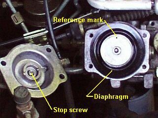
Land Rover Tdi Injection Pump Tuning

         settings at any time if you require. It is possible to file a small notch in the screw.

4. Doing the adjustments
There are two (at least?) ways to approach the ‘tuning’ process. The ‘conventional’
approach is to start with simple stop screw adjustments and work inward towards the more
complex adjustments. I believe a better method is to start from the most fundamental
adjustment, the diaphragm position, and then progressively refine the tuning with the finer
adjustments. However, I will present the tuning process in two stages to encompass the
advantages of both approaches.

Adjustments Stage 1
An immediate and noticeable improvement in off-idle pick-up can be had by adjusting only
the stop screw. If not confident about delving further into the innards of the boost
compensator, this is a good place to start. You will need a T-27 Torx bit and a 13mm socket.
Amongst other sources, Torx bits can be purchased in fairly cheap sets from Dick Smith
Electronics.
After removing the screw cap, just ‘crack’ the locknut loose, taking care to avoid moving the
Torx screw (see Figure 7). If not corroded, the locknut should turn freely without disturbing
the screw. If so, loosen the locknut about one turn. Now, taking careful note of the amount
of movement, turn the Torx screw inwards (CW) 1½ turns. Carefully re-tighten the locknut.
The diaphragm cover is light die-cast alloy – do not over-tighten any nuts/screws.
Now take it for a drive. If your engine was ‘factory standard’ to begin with, this should have a
noticeable effect on off-idle and low boost (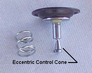
Land Rover Tdi Injection Pump Tuning

the test hill at full throttle and >2500rpm, to establish the level of black smoke (if any) and, if
possible, record the maximum EGT. Also desirable is an observer to monitor smoke levels
while the driver concentrates on driving…
To proceed, then:
Stage 2A: Remove the four slotted pan-head screws securing the diaphragm top cover and
lift off the cover (see Figure 4). Take care not to kink or damage the boost pressure signal
tube. Next, locate and record the position of the diaphragm reference mark in terms of
(approx.) degrees CW or CCW from the 12 o’clock (top) position. For example, my original
position was about 100° CCW (or between 8 and 9 o’clock, if you prefer).
Now, rotate the diaphragm in either direction until it ‘pops’ up and then withdraw the
diaphragm/control cone from the well (see Figure 3). Take care that the spring does not fall
out. You should now be able to see the ‘starwheel’ and perhaps the end of the stroke limit
pin in the bottom of the well (see Figure 2). If the stroke limit pin is not visible, operate the
throttle lever by hand and the pin should be pushed back into the well. Release the throttle
lever and carefully push the stroke limit pin forward with a small screwdriver, to allow the
control cone to be returned later.
Next, examine the assembly and work out where the reference mark is when the control
cone is in the most rearward position (relative to the front/drive end of the pump). In my case
the reference mark is at 12 o’clock when the control cone is rearward. Wherever the mark is
for your diaphragm, record this as your “maximum” position – the position which will give
maximum fuel delivery for any given level of diaphragm depression. And this is as good a
place to start as any.
Return the assembly to the well, ensuring the spring is correctly seated, and rotate to
reference mark to the “maximum” position. Do not make any other adjustments at this time.
Now take a drive up the test hill at full throttle and check the smoke level once full boost is
achieved (say, above 2500 rpm). Do not be too concerned about smoke emissions at no
boost/low boost engine speeds (under 2500 rpm) at this point.
If the black smoke is unacceptable (or EGT rises quickly to the danger zone), readjust the
diaphragm position. As mentioned earlier, if starting from the “maximum” position it doesn’t
matter which way the diaphragm is rotated. 30° increments (1 o’clock, 2 o’clock etc.) should
give noticeable changes. Continue adjustments and test runs until the results are
satisfactory (and don’t forget to record the final setting!).
Stage 2B: Once happy with the full boost performance and smoke emissions, next evaluate
the emissions as boost is increasing (typically between 1500 and 2500 rpm at full throttle in a
manual transmission vehicle). If excessively smoky, an increase in spring pre-load is
indicated. This will delay the depression of the diaphragm (and hence increased fuel
delivery) until the boost builds to a slightly higher level, reducing excessive smoke.
Conversely, if little or no smoke is being generated during full throttle acceleration through
this rpm range, a decrease in spring pre-load will add a little more fuel in this range.
Adjustments of spring pre-load in 90° (¼ turn) increments should give noticeable changes.
Record the final setting once satisfied with the results.
Stage 2C: Finally, adjust the stop screw to give acceptable off-boost performance and
smoke emission (and record it!). This is probably best achieved by repeatedly starting-off
from standstill. To obtain the best ‘launch’ performance, it may be necessary to tolerate
some smoke emission just off idle or if the engine is ever ‘lugged’ along, below 1500 rpm.

Tdi VE Adjust Rev.2.doc                     Page 7 of 8              Copyright © Ian Petersen 2003-2004
Land Rover Tdi Injection Pump Tuning

Adjustments Stage 3
No mention has yet been made of another commonly mentioned adjustment – that of the
maximum fuel delivery screw and locknut on the rear of the pump. This adjustment may
involve physical defeat of an anti-tamper device. Also, small adjustments of this screw (only
¼ turn) can cause dramatic increases in maximum EGT. Adjustments of the maximum
delivery screw should be made with extreme caution and only with an EGT gauge installed.
I have experimented with maximum delivery screw adjustments but, as my vehicle already
produces a slight black smoke haze at full throttle/full boost and will generate maximum
acceptable EGT levels after a relatively short period under full throttle/heavy load conditions,
I feel there is little potential for useful further improvement by increasing the maximum fuel
delivery, with the current amount of air available to the engine. It has been returned to the
original position.
Many other articles on this subject talk about improving the intercooling capacity by either
piping in additional intercoolers and/or upgrading the original intercooler with a higher
capacity core, etc. These measures and/or increasing the maximum boost pressure by
adjusting the wastegate setting are all aimed at increasing the maximum air mass charged
into the cylinders. If you do this then, yes, it now becomes possible to combust more fuel
and adjustment of the max. delivery screw may be justified. However, beware! - there’s only
                                                so much you can get out of 2.5 litres and
                                                expect it to give a long service life…
                                                   If such additional mods are planned my
                                                   recommendation would be to perform the
                                                   boost compensator optimization with the
                                                   ‘standard’       intercooler/boost     pressure
                                                   configuration first, then re-tune after each
                                                   additional change. That is, after fitting an
                                                   upgraded or extra intercooler or increasing
                                                   boost pressure. If the max. fuel delivery screw
                                                   is to be adjusted, I would do this first,
                                                   achieving acceptable smoke/EGT at full
                                                   throttle/heavy load, before re-tuning the boost
          Figure 9 - EGT Digital Indicator
                                                   compensator.

The end bit
The author welcomes any feedback on this article and/or references to reliable sources of
technical information on the Bosch VE pump. Please send any comments/information to
ian@thermoguard.com.au . Digital EGT gauges, with maximum temperature recording, can
be obtained from ThermoGuard Instruments [ www.thermoguard.com.au ].
Hope this information is found useful.
Ian Petersen
ThermoGuard Instruments
Revision Notes:
 Revision      Date         Description
    0          Jan 2003     Original Issue.
    1          May 2003     Some terminology changed to match Robert Bosch Technical Instructions.
    2          Jul 2004     Minor revisions to improve clarity

Tdi VE Adjust Rev.2.doc                       Page 8 of 8             Copyright © Ian Petersen 2003-2004
You can also read