Effect of Magnetic Field Coupled Deep Cryogenic Treatment on Wear Resistance of AISI 4140 Steel
←
→
Page content transcription
If your browser does not render page correctly, please read the page content below

Hindawi
Advances in Materials Science and Engineering
Volume 2020, Article ID 2589283, 8 pages
https://doi.org/10.1155/2020/2589283

Research Article
Effect of Magnetic Field Coupled Deep Cryogenic Treatment on
Wear Resistance of AISI 4140 Steel

          Liang Tang, Xianguo Yan , Yijiang Jiang, Fan Li, and Haidong Zhang
          School of Mechanical Engineering, Taiyuan University of Science and Technology, Taiyuan 030024, China

          Correspondence should be addressed to Xianguo Yan; yan_xg2008@126.com

          Received 5 December 2019; Accepted 18 February 2020; Published 30 March 2020

          Academic Editor: Guru P. Dinda

          Copyright © 2020 Liang Tang et al. This is an open access article distributed under the Creative Commons Attribution License,
          which permits unrestricted use, distribution, and reproduction in any medium, provided the original work is properly cited.

          In this study, a new magnetic field coupled deep cryogenic treatment (MDCT) is developed and its effect on wear resistance of
          AISI 4140 steel is investigated. Compared with wear resistance of untreatment (UT), wear resistance of MDCT increases by 29%.
          Wear resistance is inversely proportional to the friction coefficient. The treatment promotes the phase transformation and
          dislocation movement to generate more martensite in multidirectional distribution and optimized carbide. It enhances material
          property and repairs surface defect. Moreover, the wear mechanism of MDCT is only abrasive wear in the form of microscopic
          cutting, while other process groups are oxidative wear and abrasive wear in the form of microscopic cutting and
          microscopic fracture.

1. Introduction                                                       the property of high-speed steel T1 [8–10]. The process is
                                                                      then gradually extended to other materials. The grinding
Conical pick is a cutting tool that is widely used in mining          wear performance of cryotreated Cr-Mn-Cu alloy iron is
coal. It is composed of cemented carbide tip embedded in              better than that of conventionally destabilized [11]. For AISI
alloy steel body. Due to excellent mechanical property and            4140 steel, the paper obtains optimal level of the cryogenic
low cost, the AISI 4140 steel is often selected as the pick body      treatment process parameters and improves the wear re-
material. However, wear resistance of this material is still          sistance of the material [12].
lower than cemented carbide tip. Under the complicated                    In addition to cryogenic treatment, scholars magnetize
working condition, the pick body is most likely to cause wear         material with ferromagnetism to enhance the material
failure [1]. It leads to the pick tip falloff and directly affects      property [13–16]. There are two ways to apply magnetic field.
efficiency of the coal mining machine (Figure 1). Therefore,            The first way is to test performance after magnetic field
it is especially necessary to improve the wear resistance of          treatment. Ma [17] investigates mechanical property
material. Wear resistance is often related to structure design,       changing mechanism of high-speed steel by pulsed magnetic
material choice, and process treatment. Among them,                   treatment. This proposed method can be effective in im-
process treatment is a convenient and effective measure.               proving the high-speed steel tool life. The other way is to test
     Cryogenic treatment is an efficient method to enhance              performance under magnetic field treatment. Ayhan [18]
the materials property and the service life, which has been           studies fatigue life of AISI 4140 steel under magnetic field
widely recognized by scholars [2–5]. The principle of                 intensities. The fatigue life approximately improved by 20%,
cryogenic treatment is to lower the temperature of the                when magnetic field intensity is increased.
material to the ultralow temperature state. The low tem-                  The above two treatments have common advantages
perature environment strengthens the material to improve              such as green and controllable cost and easy implementa-
performance [6, 7]. Cryogenic treatment has a very early              tion. However, few scholars study the combination of
research history. In the 1930s and 1940s, many researchers            magnetic field and cryogenic treatment and comprehensive
begin to explore the effect of low temperature treatment on            analysis of wear is also lacking. Therefore, based on the
2                                                                                                     Advances in Materials Science and Engineering

                                                                                       Table 1: Ingredient of AISI 4140 steel (%, mass fraction).
                                                                   Element C     Si Mn Cr Mo         P    S    Ni    Fe
                                                                   Content 0.42 0.25 0.59 1.0 0.17 0.014 0.01 0.03 Balance

         Cemented                             Coal bed
         carbide tip

                Alloy steel                                                                   Microscopic                                                        Hardness
                   body                                                                       observation                           Wear scar                     point

       Figure 1: Schematic diagram of the conical pick.                                                       Figure 2: Object of specimen.

failure mode of pick body, this paper applies the magnetic
field coupled cryogenic treatment to study the wear resis-
tance of AISI 4140 steel.                                                                  Austenzing at                                                  Deep cryogenic system
                                                                                         1143 K for 20 mins
                                                                                                                                                                             Specimen
                                                                     Temperature (K)

                                                                                                         Oil
2. Materials and Methods                                                                              quenching

                                                                                                                                                         Tempering at 633K for 2 hours
2.1. Preparation of the Materials. AISI 4140 steel ingredient is
shown in Table 1. It has high strength, good hardness, and                                                            Magnetic field
                                                                                                                                     Tempering at 423K
                                                                                                                                        for 20mins
wear resistance, but no obvious temper brittleness. It has                                                              at 0.32 T

been widely used with high fatigue reliability and good load
                                                                                                                                                                                  Time (hr)
carrying capacity after heat treatment. The test specimen is
shown in Figure 2.                                                                                                Deep cryogenic treatment at
                                                                                                                      113 K for 12 hours

                                                                                             Figure 3: Schematic diagram of process setting.
2.2. Process Formulation. Conventional heat treatment
generally involves quenching and tempering. The researcher         coupled deep cryogenic treatment group (MDCT). The
has found that the sequence of cryogenic treatment is best         specific process program is shown in Table 2.
between quenching and tempering [19]. This paper was to
integrate static magnetic field on the basis of cryogenic
treatment. The process was set to four stages: quenching,          2.3. Hardness and Wear Test. Hardness is the ability of a
magnetic field coupled deep cryogenic treatment, low                material to resist the pressing of hard objects into its surface.
temperature tempering, and medium temperature temper-              The hardness was measured as a HRC-150A Rockwell
ing. Low temperature tempering can effectively resist               hardness tester with a range of 20–70 HRC. Five hardness
coarsening of carbide [20]. The specific process setting is         points were selected near the wear scar (Figure 2).
shown in Figure 3.                                                     After the hardness test above, the same specimen can
    As shown in Figure 3, cryogenic treatment was carried          been used for wear resistance test. The wear equipment was
out in cryogenic treatment system by gasification endo-             the CFT-I material surface wear tester. It also records the
thermic of liquid nitrogen. The best cryogenic tempera-            dynamic friction coefficient in wear. Based on the tested to
ture set as 113 K [21]. It belongs to deep cryogenic               better simulate the actual working conditions, the specimen
treatment (113–77 K). The realization of the magnetic field         selected the rotary friction. The grinding block material was
was based on two NdFeB permanent magnets [22]. The                 selected from Si3N4 ceramic ball of 5 mm in diameter. The
magnetic field should be placed in the center of cryogenic          other parameter setting is shown in Table 3 [21]. Before and
treatment system.                                                  after wear, the average was m1 and m2, respectively. So, the
    After the process setting was determined, it was nec-          wear ratio was (m1-m2)/m1.
essary to design a scientific test program. According to the
process setting, there were four process groups in test:
untreatment group (UT), heat treatment group (HT), deep            2.4. Microscopic Observation. The main instruments used in
cryogenic treatment group (DCT) and magnetic field                  microscopic observation were scanning electron microscope
Advances in Materials Science and Engineering                                                                                                              3

                                                                             Table 2: Process program.
Group                                      Quenching               Deep cryogenic treatment                    Magnetic field treatment           Tempering
UT                                            N                               N                                          N                          N
HT                                            Y                               N                                          N                          Y
DCT                                           Y                               Y                                          N                          Y
MDCT                                          Y                               Y                                          Y                          Y
“Y” means yes and “N” means no.

                                                                        Table 3: Rotary wear test parameter.
Normal load (N)                                              Turning radius (mm)                          Sliding speed (r/min)                 Time (min)
100                                                                   7                                            200                              40

                            0.8                                                          1.2                                                    0.8   70

                            0.7                                                                                                                 0.6
     Friction coefficient

                                                                                         0.9                                                          60

                            0.6                                                                                                                 0.4

                                                                                         0.6                                                          50
                            0.5                                                                                                                 0.2

                            0.4                                                          0.3                                                    0.0   40
                                  0         10       20            30          40                   UT             HT            DCT     MDCT
                                                  Time (min)                                        Wear rate (%)
                                                                                                    Friction coefficient
                                      UT                         DCT
                                                                                                    Hardness (HRC)
                                      HT                         MDCT
                                                       (a)                                                                 (b)

 Figure 4: Mechanical property of process groups: (a) Dynamic friction coefficient; (b) wear rate, friction coefficient, and hardness.

(SEM) and X-ray diffraction (XRD). Microscopic specimens                                        of HT, DCT, and MDCT increases by about 3.2%, 8.8%, and
were taken at the wear scar location (Figure 2). The man-                                      29%, respectively. Furthermore, the wear rate has the same
ufacturer of SEM is VEGA3 SBH from the Czech Republic.                                         reduction tendency as the friction coefficient. Hardness has
The manufacturer of XRD is MiniFlex600 Rigaku from                                             no trend as above. Although the trend is to decrease
Japan.                                                                                         gradually, the maximum reduction rate is only 4.7%. The
                                                                                               values are mainly distributed around 45HRC. So, we can
3. Results and Discussion                                                                      conclude that wear resistance is inversely proportional to
                                                                                               friction coefficient but is irrelevant to hardness. Friction
3.1. Mechanical Property. Friction coefficient is an impor-                                      coefficient reduction may enhance wear resistance. How-
tant parameter in tribology, which can reflect the friction                                     ever, Bowden’s [23] friction theory indicates that the co-
surface condition to a certain extent. As shown in                                             efficient of friction cannot satisfactorily explain the reason
Figure 4(a), friction coefficient of process groups tend to be                                   for enhancement of wear resistance. We need to obtain a
consistent in line spectrum shape. The numerical fluctuation                                    more sufficient reason through microscopic analysis.
range is small. This means that friction and wear stages are
relatively stable. But friction coefficient values of each group
are different. It can also be seen that the average friction                                    3.2. Microstructure. Figure 5 shows the tempered structure
coefficient decreases from UT about 0.63, HT, DCT to                                             of the specimen by SEM observation. It can be judged in the
MDCT about 0.52. The maximum reduction rate is 17%.                                            figure: irregularly shaped grain boundary, white grainy
These indicate that MDCT reduces the degree of friction.                                       carbide, gray-black ferrite, and white strip tempered
    Figure 4(b) shows the wear rate, average friction coef-                                    troostite. Carbide and ferrite are conventional structure
ficient, and hardness of different process groups. It is found                                   under heat treatment. There are three reasons why the white
that wear rate is reduced from UT, HT, DCT to MDCT. It                                         strip is troostite: the temperature of medium temperature
indicates that the wear resistance of each group increases in                                  tempering is 633 K; the carbon content is about 0.42%; and
order. Compared with wear resistance of UT, wear resistance                                    the hardness is about 45HRC [24]. In the quenching stage,
4 Advances in Materials Science and Engineering
Ferrite
Grain
boundary
Tempered troostite
Figure 5: SEM image of tempered structure (10.00 kx).
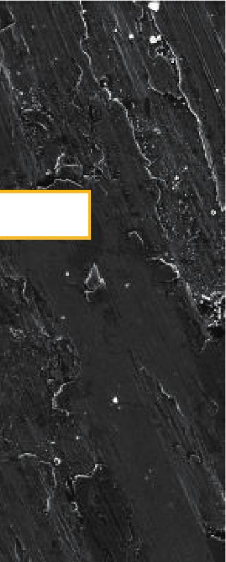
Pit Troostite
Acicular troostite
Ferrite
(a) (b)
Carbide
Strip troostite
Ferrite
(c) (d)
Figure 6: SEM images of process groups (3.00 kx): (a) UT, (b) HT, (c) DCT, (d) MDCT.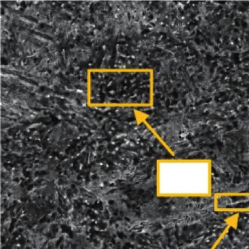
Advances in Materials Science and Engineering                                                                                                                                                                   5

                                                                                                                                                   Cementite-(111)

                               Ferrite-(002)
        Intensity (a.u)

                                                                                                                     Intensity (a.u)
                                               Ferrite-(200)                        Ferrite-(211)                                                             Cementite-(220)            Cementite-(131)

                          60           65             70                           75         80         85                            25       30           35          40         45         50          55
                                                           2θ (°)                                                                                                       2θ (°)

                                 UT                                                MDCT                                                     UT                                   MDCT
                                 HT                                                Ferrite                                                  HT                                   Cementite
                                 DCT                                                                                                        DCT
                                                           (a)                                                                                                          (b)

                                                                                                 Cr7C3-(124)
                                                                 Intensity (a.u)

                                                                                   Cr7C3-(024)
                                                                                                                                       Cr7C3-(221)
                                                                                                                                                     Cr7C3-(024)

                                                                              38         40         42   44                        46         48        50         52
                                                                                                               2θ (°)

                                                                                        UT                                              MDCT
                                                                                        HT                                              Cr7C3
                                                                                        DCT
                                                                                                               (c)

                                               Figure 7: XRD pattern of process groups: (a) ferrite, (b) cementite, and (c) Cr7C3.

austenite is transformed into martensite by continuous                                                                    troostite alternately distributes with thin strip ferrite. The
cooling. During the medium temperature tempering stage,                                                                   quenching promotes the transformation of austenite to
carbon precipitation in martensite begins to aggregate and                                                                martensite, which in turn transforms into troostite in
grow to cementite (Fe3C). The matrix martensite is restored                                                               tempering. The pit is also significantly reduced. They prompt
to ferrite. The two phases are mechanically mixed into                                                                    a slight increase on wear resistance.
tempered troostite. It has high wear resistance, strength, and
hardness [25].
                                                                                                                          3.2.2. Effect of Deep Cryogenic Treatment. Figure 6(c) shows
                                                                                                                          a quantity of thickness strip troostite and ferrite. A small
3.2.1. Effect of Conventional Heat Treatment. In Figure 6(a),                                                              amount of gaps were distributed on the surface of the
the white troostite has sparse and brittle acicular distribution                                                          material. DCT transforms more troostite and carbide. The
with many microgaps. White acicular troostite is the least                                                                reason is that DCT can lower the temperature below Ms
and the distribution is poor. There are many large particle                                                               (start temperature of martensite transformation) to generate
carbide and black honeycomb pit. This characteristic causes                                                               more martensite [26]. The transformed troostite also in-
uneven force in the wear test. The pit is easily broken by the                                                            creased in the later tempering. Carbon accumulates at the
ceramic ball. These lead to the worst performance on wear                                                                 martensite boundary to form cementite (FeC3) or carbide
resistance. Figure 6(b) shows a little distribution of small                                                              (Cr7C3) [27]. The granular carbide is mostly distributed in
granular white carbide and uneven white strip troostite. The                                                              discontinuous areas. The result is that the hardness can be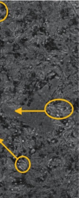
6                                                                             Advances in Materials Science and Engineering

                                                                                Oxidative wear

                              Microscopic fracture

                                         (a)                                          (b)

                                                                          Microscopic cutting

                                         (c)                                          (d)

         Figure 8: SEM images of wear scar on different process surfaces (500x): (a) UT, (b) HT, (c) DCT, and (d) MDCT.

increased. In addition, the matrix martensite is also opti-      also break down carbide [31]. The refined carbide
mized during the precipitation of carbon. Therefore, the         strengthens the matrix martensite. These factors make a
wear resistance of the DCT is greatly enhanced.                  large amount of troostite to fill material surface. Therefore,
                                                                 the group has the highest wear resistance.
                                                                     The content of troostite and carbide can also be obtained
3.2.3. Effect of Magnetic Field Coupled Deep Cryogenic            by XRD analysis. Figures 7(a) and 7(b) show the results of
Treatment. Figure 6(d) reveals best troostite distribution.      ferrite and cementite, respectively. They are the necessary
The strip troostite is thicker and denser in multidirectional    phases of the composition of the troostite. It can be seen that
distribution. This indicates that more optimized troostite is    the peaks of DCT and MDCT are matched, while other
produced than in cryogenic treatment. On the basis of the        processes have large deviations. This shows that a large
deep cryogenic treatment to lower the temperature, the           amount of troostite is produced. In addition, it can be seen
magnetic field treatment changes Gibbs free energy. This will     from Figure 7(c) that MDCT has the highest carbide content.
increase Ms and more easily induce martensite transfor-          According to the above analysis, MCDT is the most ideal
mation [28, 29]. Besides, the magnetostrictive effect activates   distribution of troostite and carbide.
flexible dislocation movement in all directions [30]. Mul-
tidirectional troostite distribution optimizes surface
roughness. So, the treatment eliminates unfavorable gaps         3.3. Wear Mechanism. The analysis of wear mechanism is
and repairs microscopic defect. Dislocation movement can         necessary to wear. SEM can observe the surface wear scar of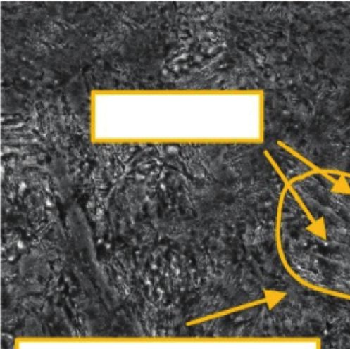
Advances in Materials Science and Engineering                                                                                     7

different groups. Figure 8 shows a clear elongated cutting               multidirectional distribution and optimized carbide.
groove with curvature in four images. In the wear test, the             The result strengthens material property and repairs
rotary friction motion is performed between the ceramic ball            surface defects. Based on the cryogenic treatment,
and the specimen. The higher hardness ceramic ball can                  the best wear resistance is obtained.
cause plastic deformation on the surface of specimen. The           (4) The mechanism of MDCT is abrasive wear in the
huge cutting stress pushes the material to both sides. The              form of microscopic cutting, while other process
surface forms many small width and depth cutting grooves                groups are oxidative wear and abrasive wear in the
with small chips. The wear mechanism is abrasive wear in the            form of microscopic cutting and microscopic
form of microscopic cutting [32].                                       fracture.
    Figures 8(a) and 8(b) have similar wear character-
istics. In addition to cutting groove, the surface of
                                                                Data Availability
specimen presents large delaminated areas and patchy
dark areas. When cut depth reaches a critical depth, a          The data used to support the findings of this study are
large amount of brittle structure is cracked in the wear        available from the corresponding author upon request.
test. The expansion of the crack and its own unfavorable
pit lead to a large delaminated area. The wear mecha-           Conflicts of Interest
nism is abrasive wear in the form of microscopic
fracture [33]. The dark area made oxidation reaction            The authors declare that there are no conflicts of interest
with friction heat. The surface is subjected to oxidative       regarding the publication of this paper.
wear [34]. Therefore, the main wear mechanisms of UT
and HT are oxidative wear and abrasive wear in the              Acknowledgments
form of microscopic cutting and microscopic fracture.
The result is a higher wear rate in both groups. How-           This work was supported by the Natural Science Foundation
ever, the delaminated area and the black area are sig-          of China (NSFC) (Grant no. 51275333).
nificantly reduced in Figure 8(c). The surface has many
evenly spaced cutting grooves with few black areas. The         References
wear mechanism is microscopic cutting but little oxi-
dative wear. The reason is that the surface has tempered         [1] S. Dewangan, S. Chattopadhyaya, and S. Hloch, “Wear as-
troostite with high strength and toughness. In                       sessment of conical pick used in coal cutting operation,” Rock
Figure 8(d), there are only grooves on the surface. As               Mechanics and Rock Engineering, vol. 48, no. 5, pp. 2129–2139,
material property is further enhanced, the cutting stress            2015.
only pushes the material to both sides without greater           [2] M. Araghchi, H. Mansouri, and R. Vafaei, “Influence of
                                                                     cryogenic thermal treatment on mechanical properties of an
damage. Therefore, MDCT is the most satisfactory wear
                                                                     Al-Cu-Mg alloy,” Materials Science and Technology, vol. 34,
resistance performance. In summary, type and degree                  no. 4, pp. 468–472, 2018.
of wear are successively reduced from UT, HT, DCT to             [3] A. Molinari, M. Pellizzari, S. Gialanella, G. Straffelini, and
MDCT.                                                                K. H. Stiasny, “Effect of deep cryogenic treatment on the
                                                                     mechanical properties of tool steels,” Journal of Materials
4. Conclusion                                                        Processing Technology, vol. 118, no. 1–3, pp. 350–355, 2001.
                                                                 [4] N. A. Özbek, A. Çiçek, M. Gülesin, and O. Özbek, “Effect of
In this study, the effect of magnetic field coupled deep               cutting conditions on wear performance of cryogenically
cryogenic treatment on wear resistance of AISI 4140 steel has        treated tungsten carbide inserts in dry turning of stainless
been investigated. From the mechanical performance testing           steel,” Tribology International, vol. 94, no. 1, pp. 223–233,
                                                                     2016.
and microanalysis, the following conclusions have been
                                                                 [5] V. Franco Steier, E. S. Ashiuchi, L. Reißig, and J. A. Araújo,
drawn.                                                               “Effect of a deep cryogenic treatment on wear and micro-
   (1) For AISI 4140 steel, compared with wear resistance            structure of a 6101 aluminum alloy,” Advances in Materials
       of UT, wear resistance of HT, DCT, and MDCT                   Science and Engineering, vol. 2016, Article ID 1582490,
       increased by about 3.2%, 8.8%, and 29%, respec-               12 pages, 2016.
                                                                 [6] S. Li and X. Wu, “Microstructural evolution and corre-
       tively. Besides, wear resistance is inversely propor-
                                                                     sponding property changes after deep cryotreatment of tool
       tional to friction coefficient but irrelevant to                steel,” Materials Science and Technology, vol. 31, no. 15,
       hardness.                                                     pp. 1867–1878, 2015.
   (2) DCT lowers temperature to generate more mar-              [7] M. Koneshlou, K. Meshinchi Asl, and F. Khomamizadeh,
       tensite. The carbon in martensite precipitates as             “Effect of cryogenic treatment on microstructure, mechanical
       cementite or carbide. The matrix martensite is also           and wear behaviors of AISI H13 hot work tool steel,” Cryo-
       optimized during the precipitation of carbon. The             genics, vol. 51, no. 1, pp. 55–61, 2011.
       wear resistance of the DCT is greatly enhanced.           [8] A. P. Gulyaev, “Improved methods of heat treating high speed
                                                                     steels to improve the cutting properties,” Metallurg, vol. 12,
   (3) MDCT can raise Ms to generate more martensite.                pp. 65–77, 1937.
       The magnetostrictive effect activates flexible dislo-       [9] P. Gordon and M. Cohen, “The transformation of retained
       cation movement in all directions. This leads to              austenite in high speed steel at sub-atmospheric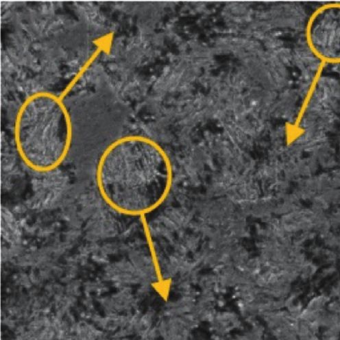
8                                                                                          Advances in Materials Science and Engineering

       temperatures,” Transactions of the American Society of Metals,       [26] D. Das, A. K. Dutta, and K. K. Ray, “Optimization of the
       vol. 30, pp. 569–587, 1942.                                               duration of cryogenic processing to maximize wear resistance
[10]   G. B. Berlien, “Sub-Zero hardening cycles,” Steel, vol. 1, no. 10,        of AISI D2 steel,” Cryogenics, vol. 49, no. 5, pp. 176–184, 2009.
       pp. 86–90, 1944.                                                     [27] S. Li, L. Deng, X. Wu, Y. a. Min, and H. Wang, “Influence of
[11]   M. K. Vidyarthi, A. K. Ghose, and I. Chakrabarty, “Effect of               deep cryogenic treatment on microstructure and evaluation
       deep cryogenic treatment on the microstructure and wear                   by internal friction of a tool steel,” Cryogenics, vol. 50, no. 11-
       performance of Cr-Mn-Cu white cast iron grinding media,”                  12, pp. 754–758, 2010.
       Cryogenics, vol. 58, pp. 85–92, 2013.                                [28] Y. Zhang, N. Gey, C. He, X. Zhao, L. Zuo, and C. Esling, “High
[12]   D. Senthilkumar and I. Rajendran, “Effect of cryogenic                     temperature tempering behaviors in a structural steel under
       treatment on the hardness and tensile behaviour of AISI 4140              high magnetic field,” Acta Materialia, vol. 52, no. 12,
       steel,” International Journal of Microstructure and Materials             pp. 3467–3474, 2004.
       Properties, vol. 26, no. 2, pp. 366-367, 2011.                       [29] S. Ken’ichi and K. Tomoyuki, “Effect of magnetic fields on
[13]   J. J. Soto-Bernal, R. Gonzalez-Mota, I. Rosales-Candelas, and             martensitic transformations in ferrous alloys and steels,” ISIJ
       J. A. Ortiz-Lozano, “Effects of static magnetic fields on the               International, vol. 29, pp. 97–116, 1989.
       physical, mechanical, and microstructural properties of ce-          [30] Q. Shao, J. Kang, Z. Xing et al., “Effect of pulsed magnetic field
       ment pastes,” Advances in Materials Science and Engineering,              treatment on the residual stress of 20Cr2Ni4A steel,” Journal
       vol. 2015, Article ID 934195, 9 pages, 2015.                              of Magnetism and Magnetic Materials, vol. 476, pp. 218–224,
[14]   T. Kakeshita, K. Kuroiwa, and K. Shimizu, “Effect of magneti               2019.
                                                                            [31] L. P. Ma, Z. Q. Liang, X. B. Wang, W. X. Zhao, L. Jiao, and
       fields on athermal and isothermal martensitic transformations
                                                                                 Z. B. Liu, “Influence of pulsed magnetic treatment on mi-
       in Fe-Ni-Mn alloys,” Materials Transactions, Japan Institute of
                                                                                 crostructures and mechanical properties of M42 high speed
       Metals, vol. 34, pp. 415–422, 1993.
                                                                                 steel tool,” Acta Metallurgica Sinica, vol. 51, no. 3, pp. 307–
[15]   Y. Zhang, X. Zhao, N. Bozzolo, C. He, L. Zuo, and C. Esling,
                                                                                 314, 2015, in Chinese.
       “Low Temperature tempering of a medium carbon steel in
                                                                            [32] L. Lin, Q. Mao, Y. Xia et al., “Experimental study of specific
       high magnetic field,” ISIJ International, vol. 45, no. 6,                  matching characteristics of tunnel boring machine cutter ring
       pp. 913–917, 2005.                                                        properties and rock,” Wear, vol. 378-379, pp. 1–10, 2017.
[16]   T. P. Hou, K. M. Wu, and G. He, “Effect of tempering                  [33] X. Zhang, Y. Xia, Y. Zhang et al., “Experimental study on wear
       temperature on carbide precipitation behaviours in high                   behaviors of TBM disc cutter ring under drying, water and
       strength low alloy steel under high magnetic field,” Materials             seawater conditions,” Wear, vol. 392-393, pp. 109–117, 2017.
       Science and Technology, vol. 30, no. 8, pp. 900–905, 2014.           [34] S. Q. Wang, L. Wang, Y. T. Zhao, Y. Sun, and Z. R. Yang,
[17]   L. Ma, W. Zhao, Z. Liang et al., “An investigation on the                 “Mild-to-severe wear transition and transition region of
       mechanical property changing mechanism of high speed steel                oxidative wear in steels,” Wear, vol. 306, pp. 311–320, 2017.
       by pulsed magnetic treatment,” Materials Science and Engi-
       neering: A, vol. 609, pp. 16–25, 2014.
[18]   Ç. Ayhan, Y. A. Fatih, A. Akgün, and K. Mehmet, “Effect of
       magnetic treatment on fatigue life of AISI 4140 steel,” Ma-
       terials & Design, vol. 26, pp. 700–704, 2005.
[19]   J. Li, X. Yan, X. Liang, H. Guo, and D. Y. Li, “Influence of
       different cryogenic treatments on high-temperature wear
       behavior of M2 steel,” Wear, vol. 376-377, pp. 1112–1121,
       2017.
[20]   M. Pellizzari, “Influence of deep cryogenic treatment on the
       properties of conventional and PM high speed steels,” Met-
       allurgia Italiana Impact Factor, vol. 100, no. 8, pp. 17–22,
       2008.
[21]   X. G. Yan and D. Y. Li, “Effects of the sub-zero treatment
       condition on microstructure, mechanical behavior and wear
       resistance of W9Mo3Cr4V high speed steel,” Wear, vol. 302,
       no. 1-2, pp. 854–862, 2013.
[22]   A. S. Kim and F. E. Camp, “High performance NdFeB
       magnets (invited),” Journal of Applied Physics, vol. 79, no. 8,
       p. 5035, 1996.
[23]   F. P. Bowden and D. Tabor, “Friction, lubrication and wear: a
       survey of work during the last decade,” British Journal of
       Applied Physics, vol. 17, no. 12, pp. 1521–1544, 1966.
[24]   M.-x. Wei, S.-q. Wang, L. Wang, X.-h. Wang, and K.-m. Chen,
       “Selection of heat treatment process and wear mechanism of
       high wear resistant cast hot-forging die steel,” Journal of Iron
       and Steel Research International, vol. 19, no. 5, pp. 50–57,
       2012.
[25]   S. Q. Wang, M. X. Wei, and Y. T. Zhao, “Effects of the tribo-
       oxide and matrix on dry sliding wear characteristics and
       mechanisms of a cast steel,” Wear, vol. 269, no. 5-6,
       pp. 424–434, 2010.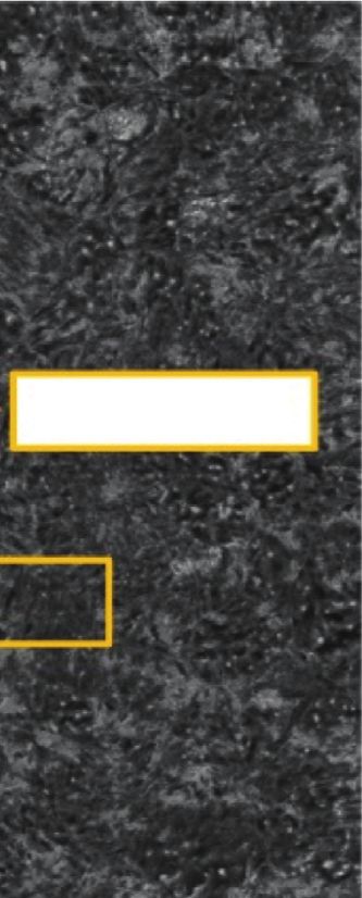
You can also read