STUDY OF MIXING BEHAVIOR OF CSTR USING CFD
←
→
Page content transcription
If your browser does not render page correctly, please read the page content below

Brazilian Journal
            of Chemical                                                                                            ISSN 0104-6632
                                                                                                                   Printed in Brazil
            Engineering                                                                                       www.abeq.org.br/bjche

  Vol. 31, No. 01, pp. 119 - 129, January - March, 2014

             STUDY OF MIXING BEHAVIOR OF CSTR
                        USING CFD
                                   D. Rajavathsavai, A. Khapre* and B. Munshi
                                  Department of Chemical Engineering, National Institute of Technology,
                                        Phone: + 91 7894044869, Rourkela, 769008, Orissa, India.
                                                  E-mail: akhilesh_khapre@yahoo.co.in

                             (Submitted: July 8, 2012 ; Revised: March 13, 2013 ; Accepted: March 20, 2013)

       Abstract - The continuous stirred tank reactor (CSTR) is a widely used equipment in chemical related
       industries. The flow behaviour of fluid inside the reactor may either change from dispersion to ideal or ideal
       to dispersion mixing state. It is studied using the computational fluid dynamics (CFD) simulation software
       ANSYS Fluent. The mixing behaviour is predicted in terms of age distribution function, I ( θ). For the CSTR
       without impeller and baffles, I ( θ) is found by the tracer injection method. It is measured and predicted by the
       impeller swept volume method for the CSTR in the presence of impeller and baffles. The predicted results are
       found to be in good agreement with the literature experimental data. Effect of rpm of the impeller, Reynolds
       number and viscosity of the process fluid on the mixing characteristics has been investigated.
       Keywords: Computational Fluid Dynamics (CFD); CSTR; Age distribution function; Laminar flow.

                     INTRODUCTION                                          The mixing performance of a CSTR can be
                                                                        characterized by residence time distribution (RTD)
    The efficiency of heat and mass transfer largely                    analysis. It provides information on how long the
depends on the extent of mixing. If the reactants are                   various fluid elements have been in the reactor. As
premixed, the reaction can start from the entry of the                  it gives a quantitative measure of the degree of
reactor. On the other hand, under non-premixed                          backmixing within a system, knowledge of the liquid
conditions, reactants must first come in contact and                    RTD is very important for designing a non-ideal
then undergo reaction. Physical phenomena/processes                     reactor (Fogler, 1999). Also, RTD represent a tool in
like diffusion, pumping of fluid in the reactor and                     successful process scale-up of chemical reactors.
mechanical agitation control the mixing (http://en.                     Many researchers have carried out experiments and
wikipidia.org/wiki/Continuous_reactor). Mixing due                      simulations (Arratia et al., 2004; Buflham, 1983;
to diffusion depends on concentration or temperature                    Danckwets, 1953 and 1958; Hocien et al., 2008;
gradients. This is commonly observed in micro reac-                     Levenspiel and Turner, 1970; Levenspiel et al., 1970;
tors. In larger reactors, mixing by diffusion is not                    Martin, 2000; Robinson and Tester, 1986; Trivedi
practically acceptable because of a low rate of                         and Vasudeva, 1974; Turner, 1982; Xiao-chang et al.,
mixing. In most cases, the continuous reactors use                      2009; Yablonskya et al., 2009; Zwietering, 1959) on
mechanical agitation for mixing. Because of agita-                      RTD of CSTR.
tion, efficient mixing can occur irrespective of                           Lipowska (1974) found the RTD of the reactor
production capacity and viscosity of the fluid. The                     without and with baffles and moving stirrer. The
mechanical agitator provides better performance of                      purpose of his work was to find the tank Reynolds
CSTR, giving more conversion of reactant to                             number, which accounts for the inlet energy, suffi-
product.                                                                cient for ideal mixing conditions. He also found the

*To whom correspondence should be addressed
120                                        D. Rajavathsavai, A. Khapre and B. Munshi

minimum number of impeller rotations required to                          The foregoing discussion shows that Lipowska
reach ideal mixing in the moving stirrer case. For                     (1974) predicted experimentally and uniquely the
ideal mixing of the liquid solely by the inlet energy,                 mixing behaviour in terms of swept volume. This
the following relations must be obeyed (Burghardt                      demands a theoretical study so that the swept volume
and Lipowska, 1972):                                                   of impeller can be used as a design parameter to
                                                                       calculate RTD of CSTR with different kinds of
       4V *ρ                                                           impeller. In view of this, extensive results of a CFD
Re =         ≥ 13.5                                        (1)         study of RTD of CSTR are reported in the present
       πDμ
                                                                       communication for a range of swept volume due to
                                                                       variation in speed of the impeller. The work covered
where Re is the tank Reynolds number based on the
                                                                       here also includes a systematic study of the effect of
tank diameter D, and ρ and µ are the liquid density
                                                                       impeller speed, viscosity of tank liquid and tank
and viscosities, respectively; V* is the inlet volumet-
                                                                       Reynolds number on RTD of CSTR. The RTD of
ric flow rate. Eq. (1) was developed for fixed
                                                                       CSTR without impeller is also studied numerically
diameters of the tank and inlet. Therefore, in terms
                                                                       by observing the tracer (potassium chloride, KCl)
of inlet diameter, d, the inlet Reynolds number, Rein
                                                                       concentration with time at the tank exit. The distribu-
can be written as:                                                     tion of KCl in the CSTR is obtained as a function of
                                                                       tank Reynolds number for better understanding the
          Re   4V *ρ                                                   nature of RTD of CSTR. Although the present study
Rein =       =       ≥ 347                                 (2)
         d D π dμ                                                      focuses on mixing in terms of RTD of CSTR,
                                                                       complementary evaluation of the hydrodynamic
   Lipowska (1974) extended the work of Burghardt                      behaviour helps to understand it better.
and Lipowska (1972) to determine the dependency
of Re and Rein on the d/D ratio. The equations are:
                                                                              CSTR GEOMETRY SPECIFICATION
                 1.09
          ⎛d⎞                                                             A flat bottom baffled agitated vessel with a six
Re ≥ 569.1⎜ ⎟                                              (3)
          ⎝D⎠                                                          bladed turbine disk impeller (Rushton turbine) used
                                                                       in the experiments by Lipowska (1974) is shown
                                                                       schematically in Figure 1. The CSTR is fitted with
                   0.09
            ⎛d⎞                                                        four symmetric baffles at a 90o interval against the
Rein ≥ 569.1⎜ ⎟                                            (4)
            ⎝D⎠                                                        tank wall. The dimensions of the tanks are given in
                                                                       Table 1. The working fluid is a water-glycerin solu-
    The above equation shows little effect of d/D                      tion and the properties of the solutions are given in
ratio on Rein . The equations allow us to calculate the                Table 2 and Table 3.
minimum inlet volumetric flow necessary for the
ideal mixing of liquid without stirrer.
    In the case of mixing with a mechanical stirrer,
the number of revolutions needed for ideal mixing
can be evaluated from:

                           0.088
                     ⎛d⎞
N = 2428.2 Re −1.215 ⎜ ⎟                                   (5)
                     ⎝D⎠

and the correlations for impeller Reynolds number,
Rem for ideal mixing is

                                       0.088
      N d m2 ρ                   ⎛d⎞
Rem =          = 269.8 Re −0.215 ⎜ ⎟                       (6)         Figure 1: Schematic diagram of the CSTR: (1) Inlet;
        μ                        ⎝D⎠                                   (2) Reactor Tank; (3) Baffles; (4) Impeller; (5) Outlet.

                                               Brazilian Journal of Chemical Engineering
Study of Mixing Behavior of CSTR Using CFD                                                 121

                                           Table 1: Dimensions of the CSTR.

   Sr. No.                  Parameters                                                            Values
      1                     Tank diameter, D                                                      0.099, 0.172, 0.250 m
      2                     Inlet diameter, d                                                     0.002, 0.0072, 0.0088 m
      3                     No of baffles                                                         4
      4                     Baffles width (bw)                                                    D/12
      5                     Type of stirrer                                                       Turbine disc impeller
      6                     Number of blades in the impeller                                      6
      7                     Ratio of impeller to the tank diameter                                (dm/D)=1/3
      8                     Length of the impeller blade, a                                       (dm/4)
      9                     Height of the impeller blade, b                                       dm/5
      10                    Clearance, C                                                          dm
      11                    Height of liquid, H                                                   D

                     Table 2: Parameters used for the CSTR without stirrer and baffles.

   Sr. No.        D (m)            d (m)              µ (cp)          ρ (kg/m3)            V* (l/hr)        τ (min)         Type of Flow
      1           0.099            0.002                 1               1000               0.621             72.6           Dispersion
      2           0.099            0.002                 1               1000               1.028            44.86           Dispersion
      3           0.099            0.002                 1               1000               1.563            29.33           Dispersion
      4           0.099            0.002                 1               1000               1.922            24.84             Ideal
      5           0.250            0.002               7.75              1141               12.82            57.44           Dispersion
      6           0.250            0.002               7.75              1141               12.30            61.07           Dispersion
      7           0.250            0.002               7.75              1141               17.42            42.27             Ideal

                        Table 3: Parameters used for the CSTR with stirrer and baffles.

   Sr. No.      D (m)          d (m)            µ (cp)         ρ (kg/m3)       V* (l/hr)         τ (min)       N (rpm)      Type of Flow
      1         0.099          0.0072             9.2             1150          2.653             20.46           50         Dispersion
      2         0.099          0.0072             9.2             1150          2.653             20.46           70         Dispersion
      3         0.099          0.0072             9.2             1150          2.524             18.11           80           Ideal
      4         0.099          0.0072             9.2             1150          2.524             18.11           90           Ideal
      5         0.172           0.002             9.8             1183          12.24             19.58           20         Dispersion
      6         0.172           0.002             9.8             1183          12.56             19.04           30         Dispersion
      7         0.172           0.002             9.8             1183          12.56             19.04           35           Ideal
      8         0.250          0.0088            19.7             1179          16.42             44.83           12         Dispersion
      9         0.250          0.0088            19.7             1179          16.50             44.60           20         Dispersion
      10        0.250          0.0088            19.7             1179          16.50             44.60           25           Ideal
      11        0.250          0.0088            19.7             1179          16.50             44.60           40           Ideal

    In ANSYS FLUENT, the default method of                             as the stirrer. The stationary zone includes the rest of
solution of the equations is in a stationary reference                 the control volume comprised of baffles, tank and
frame. However, some problems can be solved                            fluid inside the CSTR. The geometry and mesh are
advantageously in a moving reference frame where                       prepared in the ANSYS workbench and shown in
the whole computational domain moves, called a                         Figure 2 (a) and (b). The complicated CSTR geometry
single reference frame approach. But for more                          is meshed using an unstructured tetrahedral mesh.
complex problems, it is necessary to use Multiple                      There are three ways, namely coarse, medium and
Reference Frame (MRF) with the combination of                          fine mesh, to develop an unstructured mesh. The fine
stationary and moving reference frame. Here, the                       unstructured mesh is used finally to make sure of the
computational domain is divided into moving and                        stability and accuracy of the computed results. The
stationary zones with well defined interfaces be-                      unstructured tetrahedral mesh with 735231, 814782
tween the zones. The quantities such as velocity,                      and 874273 cells, covering the whole volume of the
pressure etc. are exchanged across the interface                       tanks with 0.099 m, 0.172 m and 0.250 m diameter,
between the zones. The transient behaviour of                          respectively, was used in the simulation work. As
moving part systems can be captured by a sliding                       expected, a dense mesh at the inlet, outlet of the tank
mesh approach under the MRF model. The moving                          and nearer to the stirrer surface are observed in
zone includes stirrer and rotates with the same speed                  Figure 2 (b).

                    Brazilian Journal of Chemical Engineering Vol. 31, No. 01, pp. 119 - 129, January - March, 2014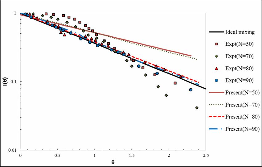
122                                        D. Rajavathsavai, A. Khapre and B. Munshi

                            (a)                                                                    (b)

                          Figure 2: (a) Computational domain; (b) Computational Mesh.

 GOVERNING EQUATIONS AND SOLUTION                                  from the solution of the species transport equation.
            ALGORITHM                                              This equation for a non-reacting mixture can be
                                                                   expressed in the following form:
   The flow prediction procedure is based on the
numerical solution of the three dimensional, time-                  ∂            ∂              ∂ ⎛          ∂ωk ⎞
dependent continuity and momentum equations. The
                                                                    ∂t
                                                                       (ρωk ) +
                                                                                ∂x j
                                                                                       (
                                                                                     ρu j ωk = )    ⎜⎜ ρDeff
                                                                                               ∂x j ⎝
                                                                                                                   ⎟
                                                                                                             ∂x j ⎟⎠
                                                                                                                       (10)
general conservation of mass or continuity can be
written as follows (ANSYS FLUENT 12 Theory guide,
2009):                                                             where ωk is the mass fraction of the k th species and
                                                                   Deff is the effective diffusivity of the species in the
∂ρ         G
   + ∇. ( ρυ ) = 0                                     (7)         mixture.
∂t
                                                                       Lipowska (1974) used a step change of potassium
      G                                                            chloride (KCl) concentration in the feed to find the
where υ is the velocity vector.
                                                                   RTD of CSTR. But he did not specify the value of
  The Navier Stokes equations is given as
                                                                   concentration of KCl in the feed stream. Thus, it
                                                                   becomes difficult to guess it exactly. Fortunately, the
∂ G             GG                       G G
   (ρυ ) + ∇. (ρυυ ) = −∇p + ∇. ( τ ) + ρg + F         (8)         expression for the RTD function, I ( θ ) (internal age
∂t
                                                                   distribution function), for the moving impeller CSTR
                                                                   is given as:
where p is the static pressure and τ is the stress
                  G       G
tensor (Eq. (9)); g and F are the gravitational body                              ⎡ ⎛V*     ⎞ ⎤
                                                                    I ( θ ) = exp ⎢ − ⎜  + 1⎟ θ⎥                       (11)
force and external body forces respectively. The                                      ⎜     ⎟
                                                                                  ⎣⎢ ⎝ Q    ⎠ ⎥⎦
stress tensor τ is given by:
                                                                   where θ = t τ , τ is the holdup time of liquid in the
       (
      ⎡ G     G
                     )
                  2 G ⎤
τ = μ ⎢ ∇υ + ∇υT − ∇.υI ⎥
      ⎣           3     ⎦
                                                       (9)         tank, V * is the inlet volumetric flow rate, Q is the im-
                                                                   peller pumping capacity.
where μ is the molecular viscosity, I is the unit                   Q = 2.3Nd m2 b cm3/sec                             (12)
tensor, and the second term on the right hand side is
the effect of volume dilatation.                                   where N is the rpm of the impeller. According to
    Simulation of mixing was carried out by intro-
                                                                   Eq. (11), mixing is ideal when V * Q → 0 .
ducing a secondary liquid as an inert tracer into the
primary liquid in the vessel. The temporal and spatial                In general, the expression of Q for impeller is
distributions of the tracer concentration were obtained            (Mishra et al., 1998):
                                           Brazilian Journal of Chemical Engineering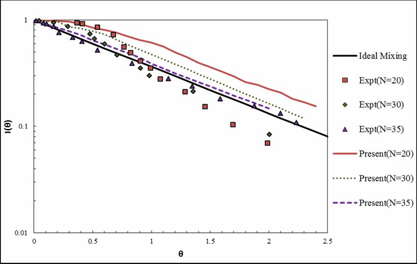
Study of Mixing Behavior of CSTR Using CFD                                   123

           D /2                       z2                                          Seidel iterative method (ANSYS FLUENT 12 Theory
Q = 2π      ∫0 ( rν )
                   z                  ∫
                             dr + πD ν r
                                      z1
                                                   dz                (13)         guide, 2009). The hydrodynamics equations of
                                                                                  CSTR without KCl species are solved first by steady
                        z1                  D /2                                  state solver to achieve an initial hydrodynamic
                                                                                  condition for the transient solver. Under convergence
where D , νr and ν z are respectively impeller di-                                of hydrodynamics equations, KCl is introduced in
ameter, radial velocity, and axial velocity; z1 and z2                            the tank by a step change. The mass fraction
are the boundaries of the impeller-swept volume in                                equations for KCl along with the hydrodynamic
the axial direction.                                                              equations are then solved by the unsteady state
    The time constant or holdup time of the reactor,                              method using the previously calculated steady state
 τ, is defined as                                                                 initial condition. The time increment is taken as 10-3
                                                                                  second, and 30 iterations per time step, which is
     V                                                                            enough to achieve a converged solution at each time
τ=                                                                   (14)         step, are taken in the simulation. All dependent
     V*                                                                           variables are modified by the under relaxation
     The above equation is used to find the liquid                                method, and used in the next iteration until the
volume, V , inside the reactor for a given τ.                                     solutions converged. The values of under-relaxation
                                                                                  factors for pressure, momentum, density, body forces
     The inlet volumetric flow rate is evaluated from
   *
                                                                                  and KCl mass equations are 0.3, 0.7, 1.0, 1.0 and 1.0,
V = Ain uin , where Ain is the inlet normal cross sec-                            respectively. The convergence criteria, i.e., residual
tional area and uin is the net inlet velocity.                                    of all the discretized equations, are satisfactorily
     In CSTR without stirrer and baffles, the definition                          taken as 10-3, and no further change in the results
of Q is not valid. Hence, different KCl concentra-                                was observed with further reduction of the residual
                                                                                  value. An overall mass balance is checked at each
tions in the feed are taken in the simulation for
                                                                                  time step. In the computations, the inlet flow rates
finding I ( θ) using the following expression:
                                                                                  and rotation of the impeller are changed from lower
                                                                                  to higher values until the computed I ( θ) matches
           C0+ − C ( t )
I ( θ) =                                                             (15)         with the ideal mixing line, exp ( −θ ) .
            C0+ − C0−

where the KCl concentration in the inlet changes
                                                                                              RESULTS AND DISCUSSION
from C0− to C0+ , and C ( t ) is the concentration of KCl
in the outlet at any time, t. The molecular diffusivity                           Study on Mixing without Stirrer and Baffles
of KCl in the solution is taken as 1.95 x 10⁻⁹ m2/s
(Harned and Nuttall, 1949).                                                           The contours of tracer concentration throughout
    In the simulation work, laminar flow with the                                 the reservoir along time are very interesting because
MRF model is used. The governing equations for the                                they provide a good perspective on the evaluation of
axial, radial and tangential velocities; and the tracer                           the concentration fronts. The concentration of KCl at
concentration ( c ) are discretized using the finite-                             the outlet of the tank is measured for a range of its
volume method. The convective terms of the govern-                                mass fraction from 10-4 to 10-6 at the inlet.
ing equations are discretized using a first order                                     Potassium chloride (KCl) is injected into the tank
upwind differencing scheme. The transient terms are                               as tracer and its concentration is noted with time at
discretized using a first order implicit scheme. A no-                            the outlet. Using the parameters given in Table 2, the
slip boundary condition is used for all the solid                                 computations are carried out with very low inlet
surfaces. Velocity at the inlet is specified. At the exit                         concentration of KCl with mass fraction in the range
of the CSTR, the gauge pressure is taken as zero.                                 of 10-4 to 10-6. For CSTR without impeller and
The rotation of the impeller is specified. The                                    baffles, contours of mass fraction of KCl at different
operating condition of the system is 293 K and                                    times are shown in Figure 3. The comparison reveals
101325 Pa. Finally, the discretized Navier–Stokes                                 that KCl reaches closer to the outlet with an increase
equations coupled with a pressure correction                                      in Re. This happens due to jet-like movement of KCl
equation are solved, together with the discretized                                with inlet fluid towards the opposite wall, and then
equations for tracer component balance equation,                                  its movement up along the wall surface. Due to the
iteratively using the SIMPLE (Semi-Implicit Method                                increase in inlet energy with Re, the homogeneity of
for Pressure-Linked Equation) algorithm and Gauss-                                the liquid in CSTR increases.

                             Brazilian Journal of Chemical Engineering Vol. 31, No. 01, pp. 119 - 129, January - March, 2014
124                                      D. Rajavathsavai, A. Khapre and B. Munshi

              (i) at θ = 0.4                          (ii) at θ = 1                           (iii) at θ = 2
      Figure 3: (a) The contours of KCl mass fraction for Re = 2.25, D = 0.099 m, d = 0.002 m, µ = 1 cP and
      ρ = 1000 kg/m3 for the CSTR without impeller; (i) θ = 0.4, (ii) θ = 1, (iii) θ = 2

              (i) at θ = 0.4                           (ii) at θ =1                           (iii) at θ = 2
      Figure 3: (b) The contours of KCl mass fraction for Re = 5.57, D = 0.099 m, d = 0.002m, µ = 1 cP and
      ρ = 1000 kg/m3 for the CSTR without impeller; (i) θ = 0.4, (ii) θ = 1, (iii) θ = 2.

    The mixing behaviour is quantitatively predicted
by I ( θ). It is calculated by Eq. (15) using the
simulated exit concentration of KCl at the outlet of
the CSTR. The predicted I ( θ) are compared with
both the experimental data of Lipowska (1974) and
the ideal mixing line. These are depicted in Figure 4
and Figure 5, and also tabulated in Table 2. The
results show an excellent agreement with the
experimental results. The analysis reveals that, with
increasing tank Reynolds number (Re), the hydro-
dynamics of CSTR approaches dispersion flow to the
ideal mixing state. If KCl enters the tank through a
larger diameter inlet, it spreads more in the bulk
liquid inside the tank compared to the lower diameter            Figure 4: Plot of I ( θ) vs. θ for a CSTR without
inlet. Therefore, the system approaches the ideal                stirrer and baffles and with D = 0.099 m, d = 0.002
mixing state at a much lower value of the Reynolds               m, µ = 1 cP and ρ = 1000 kg/m3. The KCl inlet mass
number as the inlet tube diameter increases from                 fraction, for Re = 2.25 and 3.64 is 10-4; for Re = 5.57
0.002 m to 0.0088 m.                                             is 10-5; for Re = 6.85 is 10-6.

                                         Brazilian Journal of Chemical Engineering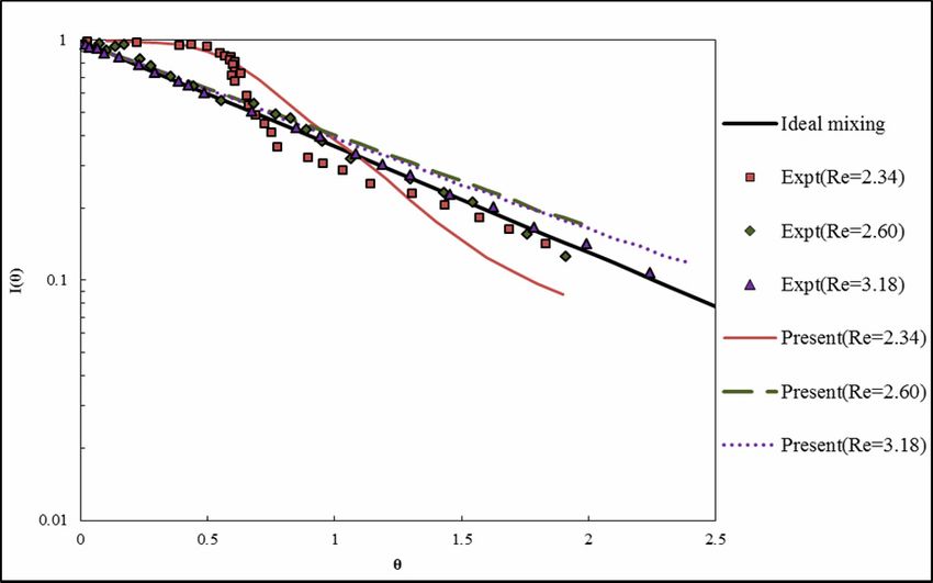
Study of Mixing Behavior of CSTR Using CFD                                          125

                                                                            At the bottom surface of the CSTR, Z is 0. The
                                                                        velocities are normalized by the impeller tip velocity
                                                                        (Vtip = πND ). The rotation of the impeller in the tank
                                                                        forms a typical double loop circulation. An effect of
                                                                        impeller speed on the velocity profiles at different
                                                                        tank diameter is clearly visible. The inlet to the
                                                                        CSTR is positioned closer to the stirrer and, hence,
                                                                        more asymmetry in the flow field is observed closer
                                                                        to the impeller surface. An increase in symmetry in
                                                                        the velocity profile is observed at higher axial
                                                                        position. This happens because of the mechanical
                                                                        energy imparted by the impeller superseding the inlet
Figure 5: Plot of I (θ) vs. θ for a CSTR without                        flow energy. The interaction of inlet fluid energy
stirrer and baffles and with D = 0.250 m, d = 0.0088 m,                 with impeller energy results in more mixing of the
µ = 7.75 cP and ρ = 1000 kg/m3. The KCl inlet mass                      fluid. A maximum velocity is observed nearer the
fraction, for Re = 2.34 and 2.60 is 10-4; for Re = 3.18                 right wall of the tank and just above the impeller.
is 10-6.                                                                This occurs due to the presence of the inlet on the
                                                                        same side and also due to the appearance of stronger
Study on Mixing with Stirrer and Baffles                                recirculation above the impeller. The velocity profile
   For the moving impeller case, the resulting veloc-                   ensures the proportionate variation of local velocities
                                                                        with impeller speeds. Nearer to the top surface, the
ity distributions in the radial direction at different
                                                                        maximum velocity is obtained nearer the rotating
axial positions are shown in Figure 6.
                                                                        shaft surface.
                                                                            A comparison of the Fluent predicted I ( θ) and
                                                                        that measured experimentally by Lipowska (1974)
                                                                        obtained by the tracer injection method is presented
                                                                        graphically in Figures 7, 8 and 9 for different rpm.
                                                                        Eq. (12) shows that the value of Q is constant for a
                                                                        particular impeller with fixed angular motion. Thus,
                                                                        the value of V * / Q is also constant for a particular run.
                                                                        Therefore, the variation of I ( θ) with θ should be
                                                                        linear on a semi-log graph. The linear variation is
                                                                        also observed in the present work. At lower impeller
                                                                        speed, the mismatch between the experimental data
                                                                        and the present values is obvious. But a careful
                           (a)
                                                                        observation shows that the computed values can
                                                                        predict the nature of fluid mixing perfectly, as
                                                                        mentioned in Table 3. According to Eq. (11), I ( θ)
                                                                        becomes ideal mixing internal age distribution func-
                                                                        tion as V * / Q tends to zero. This may be possible by
                                                                        increasing the rpm of the impeller. Therefore, the
                                                                        computed I ( θ) approaches the ideal mixing line with
                                                                        the increase in impeller rotation ( N ) and the graphs
                                                                        depict that, at higher values of N , the CFD results
                                                                        are in excellent agreement with the experimental
                                                                        data. In the figures it is also noticed that, at the initial
                                                                        moment, there is a transient Q up to a certain θ, and
                           (b)
                                                                        hence there is a relatively better agreement of the
Figure 6: Velocity profile with radial position at differ-              computed I ( θ) with the experimental data. The study
ent axial positons for a CSTR with moving impeller                      also shows that the required rpm of the impeller
and baffles, for D = 0.099 m, d = 0.0072 m, µ = 9.2 cP                  decreases to reach the ideal mixing state with an
and ρ = 1145 kg/m3; (a) N = 50 rpm, (b) N = 90 rpm.                     increase in diameter of the vessel.

                     Brazilian Journal of Chemical Engineering Vol. 31, No. 01, pp. 119 - 129, January - March, 2014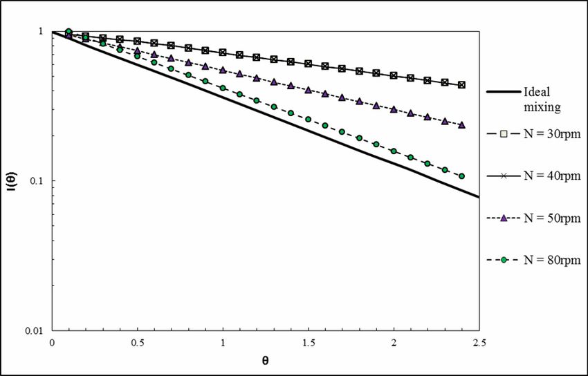
126                                          D. Rajavathsavai, A. Khapre and B. Munshi

      Figure 7: Plot of I ( θ) vs. θ for a CSTR with stirrer          Figure 8: Plot of I ( θ) vs. θ for a CSTR with stirrer
      and baffles and with D = 0.099 m, d = 0.0072 m,                 and baffles and with D = 0.172 m, d = 0.002 m,
      µ = 9.2 cP and ρ = 1145 kg/m3.                                  µ = 9.8 cP and ρ = 1163 kg/m3.

      Figure 9: Plot of I ( θ) vs. θ for a CSTR with stirrer and baffles and with D = 0.250 m, d = 0.0088 m,
      µ = 19.7 cP and ρ = 1179 kg/m3.

Effect of Tank Reynolds Number, Impeller Rotation
and Viscosity of the Liquid on the Mixing

    Simulations have been carried out to examine the
influence of parameters on I ( θ) and also to carry
out a qualitative comparison of the mixing behav-
iour. The effect of Re, N and fluid viscosity on the
mixing behavior of the liquid in a CSTR is studied.
Figure 10 represents the effect of Re on I ( θ) at
constant impeller rotation, N = 50 rpm. At Re 0.98,
dispersion flow occurs, at Re 1.03 the mixing line
goes relatively closer to ideal mixing line, and
further increase in Re to 1.5 and then to 2.03 results
in the mixing line following the ideal mixing line.                   Figure 10: Effect of tank Reynolds number, Re on
The energy of the inlet flow increases with an                        I ( θ) for a CSTR with stirrer and baffles and with
increase in V * , which increases proportionately with                D = 0.099 m, d = 0.0066 m, N = 50 rpm, µ = 9.2 cP.
Re. This inlet energy helps to mix the liquid. There-
                                                                          The effect of impeller rpm on the mixing
fore, I ( θ) approaches the ideal mixing line with an                 efficiency is demonstrated in Figure 11. It can be
increase in Re as observed in Figure 8.                               observed that the nature of the flow changes from
                                              Brazilian Journal of Chemical Engineering
Study of Mixing Behavior of CSTR Using CFD                                         127

dispersion to an ideal mixing state with the increase                     Viscosity of the fluid has a certain effect on the
in N . A distinct dispersion flow happens at N equal                  hydrodynamic and mixing behavior of the liquid.
to 30 and 40 (these two curves are superimposed),                     The effect of viscosity of the liquid on I ( θ) at
and also at 50, whereas at N = 80 the mixing is very                  different impeller speeds is shown in Figure 12. The
near to the ideal mixing condition. This happens                      effect of viscosity on I ( θ) at high N is just the re-
naturally as it is well known that the amount of
                                                                      verse of the effect observed at lower values of N .
mechanical energy imparted to the fluid increases
with an increase in N , and hence more mixing.                        Figure 12 (c) and (d) show that the mixing of the liquid
                                                                      moves towards the ideal mixing state with an in-
                                                                      crease in viscosity at rpm 50 and 70, whereas it
                                                                      moves away from the ideal mixing line for rpm 25
                                                                      and 12 as observed in Figure 12 (a) and (b). For a
                                                                      particular Re, V * increases with viscosity. In addition to
                                                                      this, the impeller does more mechanical work at
                                                                      higher values of N , and it makes the viscous force
                                                                      negligible. Thus, the increase of V * results in more
                                                                      mixing of the liquid in CSTR. The mixing of liquid
                                                                      therefore moves towards the ideal mixing condition
                                                                      at higher impeller rotation. But at lower values of
                                                                       N , the amount of energy transferred by the impeller
                                                                      to the liquid is relatively low, and it becomes insuffi-
Figure 11: Effect of N on I ( θ) for a CSTR with                      cient to overcome the viscous force. Due to domina-
stirrer and baffles and with D = 0.250 m, d = 0.0066                  tion of the viscous force at lower N, the mixing line
m, µ = 9.2 cP, ρ = 1145 kg/m3 and Re = 1.03.                          moves away from the ideal mixing line.

                            (a)                                                                      (b)

                           (c)                                                       (d)
   Figure 12: Effect of viscosity of the liquid on I ( θ) for a CSTR with stirrer and baffles with D = 0.099 m,
   d = 0.0066 m, Re = 1.03: (a) N = 10 rpm; (b) N = 25 rpm; (c) N = 50 rpm and (d) N = 70 rpm.
                   Brazilian Journal of Chemical Engineering Vol. 31, No. 01, pp. 119 - 129, January - March, 2014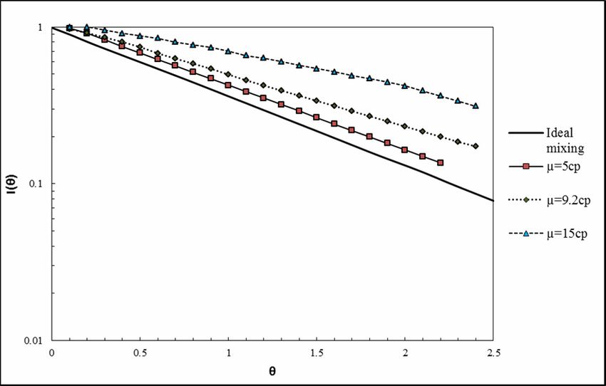
128                                       D. Rajavathsavai, A. Khapre and B. Munshi

                  CONCLUSION                                       ρ           Density                             kg/m3
                                                                   θ           Dimensionless time                     (-)
    CFD simulations have been carried out success-                 σ           Variance of the residence              (-)
fully to predict the mixing behavior of liquid in a                            time distribution
CSTR. The conclusions may be summarized as follows:
    1. The mixing predictions have been found to be
in good agreement with the experimental results                                        REFERENCES
available in the open literature.
    2. The simulation results prove that the swept                ANSYS FLUENT 12.0 Theory Guide, ANSYS Inc.
volume of the impeller can be used to predict I (θ) of               (2009).
the CSTR with impeller and baffles.                               Arratia, P. E., Lacombe, J. P., Shinbrot, T. and Muzzio,
    3. Effects of rpm of the impeller, tank Reynolds                 F. J., Segregated regions in continuous laminar
number (Re) and viscosity of the liquid on I ( θ)                    stirred tank reactors. Chemical Engineering Sci-
have been investigated.                                              ence, 59, 1481-1490 (2004).
    4. The mixing behaviour has been found to move                Buflham, B. A., Internal and external residence-time
from dispersion to ideal mixing as the rpm ( N ) of                  distributions. Chemical Engineering Communica-
the impeller increases. The effect of the viscosity of               tions, 22, 105-107 (1983).
the liquid on the mixing has been found to be rpm                 Burghardt, A. and Lipowska, L., Mixing phenomena
dependent.                                                           in a continuous flow stirred tank reactor. Chemi-
                                                                     cal Engineering Science, 27, 1783-1795 (1972).
                                                                  Continuous Reactor, Wikipedia, the Free Encyclope-
                NOMENCLATURE                                         dia, Wikimedia Foundation Inc. (2004). http://en.
                                                                     wikipidia.org/wiki/Continuous_reactor.
a        Length of the impeller blade                m            Danckwerts, P. V., Continuous flow systems: Distri-
A        Cross sectional area                        m2              bution of residence times. Chemical Engineering
b        Height of the impeller blade                m               Science, 2, 1-13 (1953).
bw       Baffle width                                m            Danckwerts, P. V., The effect of incomplete mixing
C0+      Concentration of a tracer fed           mole/L              on homogeneous reactions. Chemical Engineer-
         into the reactor after a step-                              ing Science, 8, 93-102 (1958).
         wise change                                              Fogler, H. S., Elements of Chemical Reaction Engi-
C0−      Initial concentration of a              mole/L              neering. 3rd Ed., Pearson Education Inc., New
         tracer in the reactor                                       Jersey (1999).
C (t )   Concentration of a tracer at            mole/L           Harned, H. S. and Nuttall, R. L., The differential dif-
         an outlet from the reactor at                               fusion coefficient of potassium chloride in aqueous
         the moment t                                                solutions. Journal of the American Chemical So-
D        Tank diameter                                m              ciety, 71, 1460-1463 (1949).
d        Inlet tube diameter                          m           Hocine, S., Pibouleau, L., Azzaro-Pantel, C. and
dm       Impeller diameter                            m              Domenech, S., Modelling systems defined by
H        Height of liquid tank                        m              RTD curves. Computers & Chemical Engineer-
N        Impeller speed                           RPM                ing, 32, 3112-3120 (2008).
Q        Impeller pumping capacity              m3/min            Levenspiel, O. and Turner, J. C. R., The interpreta-
Re       Tank Reynolds number                        (-)             tion of residence-time experiments. Chemical
Rem      Impeller Reynolds number                    (-)             Engineering Science, 25, 1605-1609 (1970).
Rein     Inlet Reynolds number                       (-)          Levenspiel, O., Lai, B. W. and Chatlynne, C. Y.,
t        Time                                  min/sec               Tracer curves and the residence time distribution.
uin      Inlet velocity                          m/sec               Chemical Engineering Science, 25, 1611-1613
V        Tank volume                                m3               (1970).
                                                  3
V*       Volumetric flow rate               l/hr/m /sec           Lipowska, L., The influence of geometric parameters
Vtip     Impeller tip velocity                   m/sec               on the ideal mixing range of liquid in a continu-
                                                                     ous flow stirred tank reactor. Chemical Engineer-
Greek Symbols                                                        ing Science, 29, 1901-1908 (1974).
                                                                  Martin, A. D., Interpretation of residence time distri-
τ        Time constant                                 (-)           bution data. Chemical Engineering Science, 55,
μ        Viscosity                                     cP            5907-5917 (2000).
                                          Brazilian Journal of Chemical Engineering
Study of Mixing Behavior of CSTR Using CFD 129
Mishra, V. P., Dyster, K. N., Jaworski, Z., Nienow, butions. Chemical Engineering Science, 38, 1-4
A. W. and Mckemmie, J., A study of an up and (1982).
down-pumping wide blade hydrofoil impeller: Xiao-chang, C., Ting-an, Z. and Qiu-yue, Z., Com-
Part I. LAD measurements. Canadian Journal of putational simulation of fluid dynamics in a tubu-
Chemical Engineering, 76, 577-588 (1998). lar stirred reactor. Transactions of Nonferrous
Robinson, B. A. and Tester, J. W., Characterization Metals Society of China, 19, 489-495 (2009).
of flow maldistribution using inlet-outlet tracer Yablonskya, G. S., Constalesb, D. and Marinc, G.
techniques: An application of internal residence B., A new approach to diagnostics of ideal and
time distributions. Chemical Engineering Science, non-ideal flow patterns: I, the concept of reactive-
41, 469-483 (1986). mixing index (REMI) analysis. Chemical Engi-
Trivedi, R. N. and Vasudeva, K., RTD for diffusion neering Science, 64, 4875-4883 (2009).
free laminar flow in helical coils. Chemical Zwietering, T. N., The degree of mixing in continu-
Engineering Science, 29, 2291-2295 (1974). ous flow system. Chemical Engineering Science,
Turner, J. C. R., Perspectives in residence-time distri- 11, 1-15 (1959).
Brazilian Journal of Chemical Engineering Vol. 31, No. 01, pp. 119 - 129, January - March, 2014You can also read