INTERNATIONAL JOURNAL FOR ADVANCE RESEARCH IN ENGINEERING AND TECHNOLOGY
←
→
Page content transcription
If your browser does not render page correctly, please read the page content below
Webpage: www.ijaret.org                                                                 Volume 2, Issue X, Oct 2014
                                                                                             ISSN 2320-6802

             INTERNATIONAL JOURNAL FOR ADVANCE RESEARCH IN
                      ENGINEERING AND TECHNOLOGY
                                                    WINGS TO YOUR THOUGHTS…..

     Development of High Performance and Low Cost
       Automatic Toll Payment System using RFID
          Technology for Malaysia Environment
            A. Salleh1, N. M. Z Hashim2, N. R. Mohamad3, N. A. A. Hadi4, M.Z.A Ab. Aziz5
                          1,2,3,4,5
                                Center for Telecommunication Research and Innovation (CeTRI)
                                       Faculty of Electronic & Computer Engineering
                                  Universiti Teknikal Malaysia Melaka (UTeM), Malaysia
                      1
                        azahari@utem.edu.my, 2nikzarifie@utem.edu.my, 3najmiahradhi@utem.edu.my
                                 4
                                   nikazran@utem.edu.my 5mohamadzoinol@utem.edu.my
Abstract: The proposed Automatic Toll Payment System is designed for efficient and convenient use of the public.
The system is upgraded by using passive Radio Frequency Identification (RFID) technology instead of infrared that
currently used nowadays to improve and make it low cost and have high performance toll payment system. A
Malaysian toll payment system such as Touch n’ Go and SmartTag have the constraints that can lead to traffic
congestion especially during the festival period. The RFID system uses tags that are mounted on the windshield of
vehicles, through which information embedded in the tags are read by long read range RFID reader. The passive
RFID technology is coming up with more advantages for public comfort. It is also less expensive since the passive
RFID doesn’t use internal power supply to operate and it provides high speed detection. As vehicles don’t have to
stop in a queue for making a payment, it assures time saving, fuel conservation, contributing in saving money, and
at the same time reduced pollutions. Visual basic software is needed for implementation of the system for running
the database of the entire system. The interface that has been designed, is used for output power and reading
distance analysis before installation. The frequency analysis is carried out based on reading range from 1 meter to
5 meters for efficient speed detection. Every single frequency between 902.4 MHz to 927.8 MHz has been analyzed
to gain efficiencies of tagging against the times. There are frequency band that cannot detect the transponder and
vice versa. So the frequency configuration is important during installation for public convenience.
Keywords: passive RFID, Toll Payment System, low cost.

    1. INTRODUCTION                                            SmartTag is a device that works with combination of
    Nowadays, our country has developed                        Touch ‘n Go card to allow users to pay tolls to drive
tremendously. The Malaysian Expressway Network                 through convenience. It transmits the information via
can be considered as one of the best expressway                infrared. However, the constraints of infrared are low
network in Southeast Asia. The development of                  speed detection and easy to interfere. The device is
expressway is monitored by government agencies,                also expensive [1]. This project attempts as a new
the Malaysian Highway Authority (MHA) under the                system that has an improvement on performance and
Malaysian Ministry of Works (MOW). Costly and                  low cost using RFID technology. This technology
time consuming comes to be a priority factor for               enables identification from a distance which without
designing the whole automatic toll payment system.             requiring a line of sight, and unlike earlier bar-code
Every year the total number of vehicle production in           technology. RFID tags support a larger set of unique
Malaysia is increasing significantly by depending on           IDs than bar codes, and can incorporate additional
population civilization. The consequence is the                data such as manufacturer, product type, and even
number of expressway user increased dramatically               measure environmental factors such as temperature.
and caused jammed along the routes and congested,              Furthermore, RFID systems can discern many
especially during festive seasons when traffic tends to        different tags located in the same general area
be heavier than normal, at the same time wasting               without human assistance [2]-[4].
time, fuel, money and increased pollutions [1].
                                                               Basically, for this project the system has, replaced by
Currently, Smart Tag and Touch n’ Go being used as             RFID instead of infrared for transmitting the
an automatic toll payment system in Malaysia.                  information as shown in Figure 1. It is compulsory

                                                      Page 1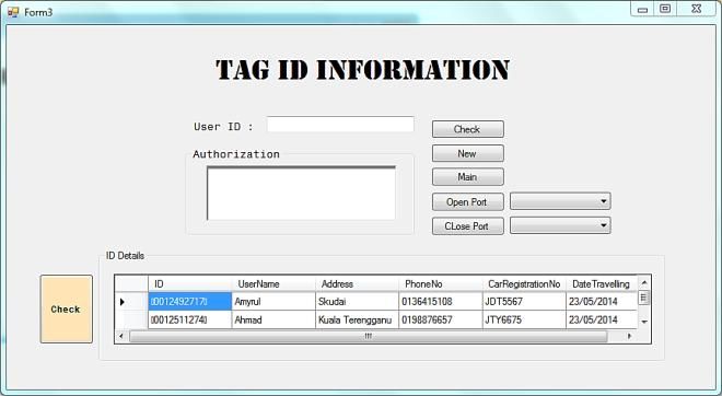
Webpage: www.ijaret.org                                                                    Volume 2, Issue X, Oct 2014
                                                                                                ISSN 2320-6802

             INTERNATIONAL JOURNAL FOR ADVANCE RESEARCH IN
                      ENGINEERING AND TECHNOLOGY
                                                     WINGS TO YOUR THOUGHTS…..
for all the vehicle owners to have a registered RFID             the comparison between proposed system and
tag attached to their vehicle's windshield. The tag              previous work of electronic toll collection (ETC).
owners should submit their detail information to be
saved in database and the specified unique code will               Table 1: Comparison between proposed work and
be embedded in the tag such as ID number,                                       previous work of ETC
username, address, phone number, car registration                 Country       Toll     System    Payment Cost
number and date travelling.                                                   Types        used    Method
RFID reader would be installed at the entrance and                Proposed      Toll     Passive   Postpaid Low
the end point of the expressway. These readers are                 system     booth       RFID         &
connected directly to the Personal Computer (PC)                                          (long     Prepaid
unit via RS232 interface. PC will be used as a                                            range
monitoring system in this project. It works as the core                                 detection)
project for controlling and monitoring the database              Philippines    Toll         -     Postpaid    -
and signal received to process the information signal                         booth
from the registered tag. When the vehicles come to                 Canada     Closed      OCR,     Postpaid High
the entrance booth, RFID reader will transmit the                             Access      Laser
signal to the tag on the user windshield. The tag will                                    Beam
receive the signal and charged enough energy to                    United      Two         Two         -       -
transmit back the information that embedded in the                 States      lanes    Antennas
tag in the form of electromagnetic waves (identifying              Poland     Closed      GSM,     Postpaid High
response). Then, the reader will send the information,                        Access       GPS
data received for the personal computer unit (PC) via             Malaysia      Toll     Infrared   Prepaid High
RS232 wired interface. PC will process the signal by                          booth
separating the ID and saved in the database.
Moreover, when the vehicles reach the end booth, the             Passive RFID tag doesn’t have an internal power
reader again will read the tag and PC system will                source (battery). The reader transmits signals to the
compare the ID to indicate a right vehicle which is              tags and the electrical current is created in the
the same vehicle that passed at the first booth to let it        antenna to outbound the signal back to the reader. It
pass exit gate.                                                  only has shorter distance read range up to 10 meters
                                                                 since there is no battery on the devices and the cost is
                                                                 less expensive compared to active and semi-passive
                                                                 tag [4]. The most important parameter on tag
                                                                 limitation is a chip sensitivity threshold which is the
                                                                 minimum received RF power necessary to turn on the
                                                                 RFID chip. Lower RF power will result the longer
                                                                 RFID detection. However, the detection sensitivity
                                                                 also depends on architecture during the fabrication
                                                                 process. Impedance can be matched at various chip
                                                                 power levels such as at minimum thresholds for
                                                                 maximizing the tag scope [6]. The RFID reader also
                                                                 has the capability to communicate with the tag
                                                                 without a direct line of sight, depending on the radio
                                                                 frequency and the type of tag (active, passive, or semi
                                                                 passive) used. Readers can process multiple items at
                                                                 once, allowing for increased read processing times.
           Figure 1: RFID in Toll System                         They can be mobile, such as handheld devices that
                                                                 scan objects like pallets and cases, or stationary, such
                                                                 as point-of-sale devices used in supermarkets [4].
    2. LITERATURE REVIEW
                                                                 Currently, toll payment system is using infrared (IR)
The electronic toll collection system is currently
                                                                 as a main technology for public usage in Malaysia.
being used throughout the world. The countries that
                                                                 However, infrared has many disadvantages compared
have applied the electronic toll collection system are
Singapore, United States, Philippines, Japan,                    to the RFID technology in term of performance and
                                                                 costing development. Table 2 shows the comparison
Canada., Poland and Malaysia. [5]. Table 1 shows
                                                                 between infrared and RFID features [7]- [8].

                                                        Page 2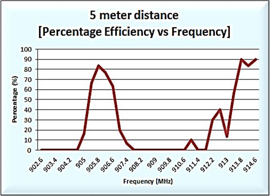
Webpage: www.ijaret.org Volume 2, Issue X, Oct 2014
ISSN 2320-6802
INTERNATIONAL JOURNAL FOR ADVANCE RESEARCH IN
ENGINEERING AND TECHNOLOGY
WINGS TO YOUR THOUGHTS…..
Table 2: Comparison between Infrared and RFID system operation. RFID acts as a sensor part of the
Parameter Infrared RFID system.There are several parameters or specifications
Battery Life More than 1 Varies that have been analyzed to ensure the performance is
year better than current system payment which is infrared
Signal 16 ft. 100 ft. technology. Table 3 shows the specification of the
Range development system design.
Tags Tags work like Tags work like
a television remote keyless Table 3: Specifications of system design.
remote control entry Specifications RFID system
Signal Area Within a room Within an area, Interface RS232 output
and contained not contained by
by walls walls Distance Adjustable
Bounces off Effective distance 5 meter
objects and
walls Output power Maximum 30 dBm
Sensors More sensors Less sensors Times/ Tagging 30
required required
Application Equipment Tracking for Frequency 902.4 MHz – 927.8
deployment periodic MHz
Tracking for maintenance
periodic General locating Figure 4 shows that the organization chart of the
maintenance project. The whole system consists of hardware and
Automated software which is the hardware is classified with
billing three different parts, input devices, output devices
and main controller. RFID act as an input device of
General
the system where PC is being put as main controller
locating
and open/close gate act as output devices. Software
development is divided by two types of software’s,
Microsoft Visual Basic Express and Microsoft
3. DESIGN METHODOLOGY Access. Both software has own functions to operate
Based on Figure 3, the transactions are made if the ID the entire system.
code is passed on authentication part. Means that, the
tags are not on barring status. At the exit point, the
system will calculate the kilometers driven and make
a payment transaction due to the account store in
database. If the tag was barred, the vehicles will be
allowed to pass the toll gate, but the warning notice
will be sent to the respective home address for further
action.
Figure 4: Organization Chart of the project
Figure 3: Data flow of proposed system Automatic Toll Payment System needs a few
software development to operate the entire system,
Hardware and software is needed in order to operate especially framework for database and compiler for
the whole system. This part will explain about structure, plan and control. This project used CCS C
components and software’s that being used on this Compiler and Microsoft Visual Basic Express
project.The electronics circuit design consists of a Software for both applications. Each windows form
desktop (PC), RFID circuit, and power supply. that has been created has their own command to
Desktop acts as a main part which control the whole execute the function of every button and other tools
Page 3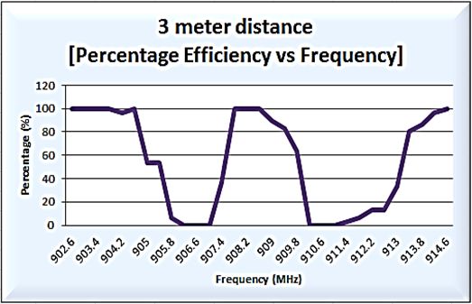
Webpage: www.ijaret.org Volume 2, Issue X, Oct 2014
ISSN 2320-6802
INTERNATIONAL JOURNAL FOR ADVANCE RESEARCH IN
ENGINEERING AND TECHNOLOGY
WINGS TO YOUR THOUGHTS…..
that has been used in that form. Database and be on for security purpose. The database system has
interface of the software created is two different checking function for reference purpose. If an
things. A database is a file created by using Microsoft administrator needs to check on an individual detail,
access to develop the account of each expressway they only enter the ID number of that client and click
user. Each line or row is represented the account per the second check button on Figure 6, the system will
person and every single row has details of the user, only show the details of the ID owner.
such as ID number, name, address, phone number,
car registration number and date travelling. Apart
from that, the database combines together with a GUI
that has been created by using visual basic express
2010 which is used to develop the overall interface of
the software system. The communication between
database and GUI is made up by source connection
with visual basic software. They have to be bound
together for interaction purpose and supporting by
command in every single function.
Microsoft Access is one of the tools that can create
and act as database applications. The collected data
can be stored automatically in a SQL database. It is Figure 5: Registration form
more secure and scalable for project purpose. The
interface created using visual basic 2010 can be
combined with Microsoft access as a database of the
project with some command on coding space. Each
particular window of an interface that has been
created must be test the connection between database
and interface. So every row and columns on the
database can be synchronized with interface windows
created.
4. RESULT AND ANALYSIS
The overall results of the proposed system including
software and hardware part. Figure 6: ID matching form
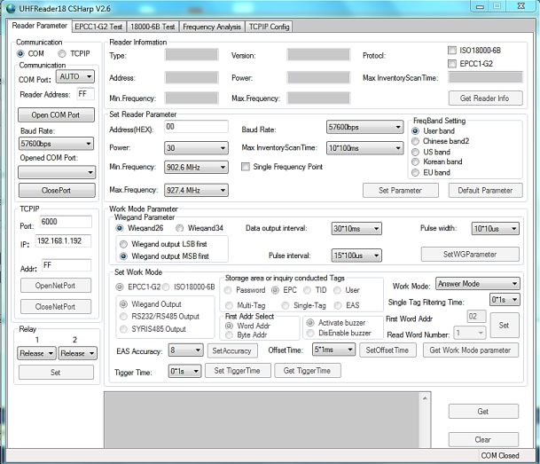
Figure 7 shows the reader configuration form during
4.1 Software
the installation process. There are so many parameter
Software parts are covered from authentication form,
needs to be adjusted such as frequency, received
registration form, checking form, database and
output power, times, baud rate and tagging type. The
configuration parameter form. Figure 5 shows the
distance of the reading signal depends on the output
registration form that saves all the details of
power of the reader to broadcast a signal through
expressway user in order to make transaction
transponder for data collection purpose. There is no
payment and ID matching during system operation.
line of sight (LoS) for this reader. Some protocol has
The details will be saved on database for
been used for frequency band setting which is ISO
administration and system references. This form will
18000-6B and EPCC1-G2. At the work mode
appear after admin of the system entering the
parameter, RS232 output was chosen for
password and username. For checking form, when we
communication between the database and reader.
click on the access button on Figure 5, another form
All information of expressway user has been stored
will be appearing. This is where the system searching
in system database which is one account for each row
for user ID that has been saved in database for
of the table as what is shown in Figure 8. The
matching purposes. When a reader scanning the
information contains of ID number, username,
transponder on the windshield of the car at the exit
address, phone number, car registration number and
point, the data ID will be compared for transaction
date traveling. Admin can easily check the details of
purpose. If the ID matched one of the codes, the gate
each user based on ID checking number.
will open, but if the ID unmatched to any data on the
database, the gate will keep close and the alarm will
Page 4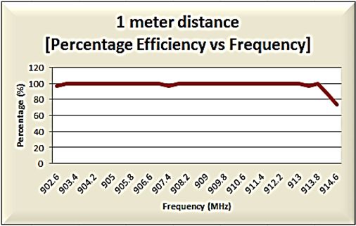
Webpage: www.ijaret.org                                                                 Volume 2, Issue X, Oct 2014
                                                                                             ISSN 2320-6802

             INTERNATIONAL JOURNAL FOR ADVANCE RESEARCH IN
                      ENGINEERING AND TECHNOLOGY
                                                    WINGS TO YOUR THOUGHTS…..
                                                               different distance between reader and the
                                                               transponder. It is not compulsory for every frequency
                                                               in band range can be 100% efficient. So, we need to
                                                               identify which frequency detection has a higher speed
                                                               detection per second. This is useful for multi tag
                                                               operation. The distance of detection is based on
                                                               output power apply from RFID reader to reach the
                                                               signal broadcast by transponder. The maximum
                                                               effective distance is 5 meters long and the maximum
                                                               output power for this reader is 30 dB. Means that, 1
                                                               meter of detection is equal to 6 dBm of output power.
                                                               The analysis can be seen as shown in Figure 9.

           Figure 7: Reader configuration

                                                                          Figure 9: Distance vs output power

                                                               Frequency analysis has been done with some
          Figure 8: Database information                       parameter is taken in consideration such as baud rate,
                                                               max inventory scan time, efficiency percentage and
4.2 Hardware                                                   times per 30 tagging. Some distance has been chosen
The operation of the system has begun when the                 for sample of analysis and the frequency range used
RFID reader detects the signal transmitted by the              is 902.6 MHz – 915.8 MHz. It takes 30 times of
passive RFID tag in the form of electromagnetic                tagging for every 0.4 MHz frequency. The number of
wave to transfer data and at the same time the                 tagging must be 30/30 per 0.4 MHz for 100%
information that's embedded in the tag will be                 efficiency. At this range, the frequency is considered
transferred to database via PC itself. The component           high speed detection. Therefore, increase the
hardware of the system. Each tag has different ID              performance of the system. The analysis is shown in
number and can read, write the information by using            Figure 10, Figure 11 and Figure 12. Figure 10 shows
configuration reader software. The type of tag card            that the percentage of efficiency and the frequency
that are used in this project doesn’t need a battery to        involved. If we look at frequency 907.4 and 913.8,
broadcast a signal. It constantly transmits the signal         the efficiency is less than 100%. Mean that, at that
based on the pattern on the tag design. So, for sure           point, the frequency is less efficient in 1 meter of
this kind of product is an environmentally friendly            reading distance. Figure 11 shows that same
unit and can maintain sustainable development.                 parameter study of the reader performance, which is
Moreover, the cost of manufacturing is less                    percentage efficiency and frequency. Lower
expensive rather than active tags.                             percentage seems to be at range 905 MHz – 908.2
There are several parameters that we take in                   MHz and 910 MHz – 913 MHz, which is error
consideration, to analyze the performance of this              detection occur at that point of view. The effect is
system. The most important parameter for automatic             less than 100 %. So those frequency ranges is not
toll payment system is the distance of transponder             practical for implementation as the detection 3 meters
detection. The measurement of distance depends on              is less effective. Figure 12 shows that the same graph,
receiving output power of the reader, which is for this        but different reading range, which is 5 meters and the
reader it can adjust up to 30 dB for maximum                   output power is 30 dBm to support reader capability
efficiency 5 meter detection. The frequency analysis           to read this range of transponder. Every meter
also needs to be done for detection checking with              consumes 6 dBm. From the graph we can see that the
                                                               frequency range 902.6 MHz – 905 MHz and 908.2

                                                      Page 5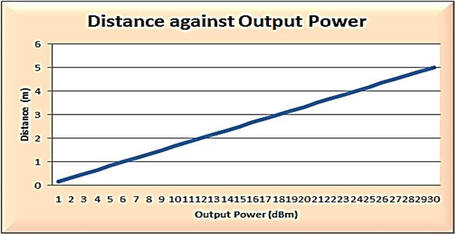
Webpage: www.ijaret.org                                                                    Volume 2, Issue X, Oct 2014
                                                                                                ISSN 2320-6802

             INTERNATIONAL JOURNAL FOR ADVANCE RESEARCH IN
                      ENGINEERING AND TECHNOLOGY
                                                     WINGS TO YOUR THOUGHTS…..
MHz – 910.6 MHz has no efficiency at all. Mean that              performance and user service costing, infrared has
the tag has not been detected in that particular                 low speed detection for reading capability and the
frequency range. 5 meter reading range for passive               range of reading is lower than RFID detection.
tag is quite long. So that at certain frequencies in this        SmartTag user has to ensure that the SmartTag
range is there is effectively detected.                          device is positioned properly and have adequate
                                                                 balance of their journey. The user must slow down
                                                                 the vehicles when nearing to the Smart Tag lane and
                                                                 they can’t follow too close to car in-front of them. In
                                                                 case if the SmartTag is not detected, they have to
                                                                 touch the card (Touch ‘n Go) to the available card
                                                                 reader at that particular lane.
                                                                 In terms of costing, SmartTag required high
                                                                 manufacturing cost and high expense for the user as
                                                                 they have to purchase the SmartTag devices that cost
                                                                 about RM 80.00 per device. This is not included
                                                                 Touch n’ Go card that have to top up the amount as it
                                                                 act as a debit card and used together with the Smart
                                                                 Tag device to transmit the signal. Active tag more
                                                                 expensive than passive tag because the passive tag
 Figure 10: Frequency analysis for 1 meter distance              does not require a battery to transmit the signal to the
                                                                 reader. The passive tag constantly broadcast signal in
                                                                 the form of electromagnetic wave. So that the reader
                                                                 can read the data transmitted by the tag for access
                                                                 purposes.
                                                                 The passive RFID tag doesn’t need a battery to
                                                                 supply power to transmit or broadcast the signal to
                                                                 the reader. It transmits signals in the form of
                                                                 electromagnetic wave constantly. So that the
                                                                 environment can be sustained since batteries are not
                                                                 included in this system. When battery drain and
                                                                 unchangeable, it cannot be disposed completely. If
                                                                 toll payment system used battery on every single tag,
                                                                 it can cause pollution to our environment. However,
                                                                 the automatic toll payment system uses passive tag
                                                                 and it is environmentally friendly and the
 Figure 11: Frequency analysis for 1 meter distance              commercialized process can be made easily because
                                                                 this system has high performance, low cost and does
                                                                 not pollute an environment. The cost of passive tag is
                                                                 less expensive because no battery required for signal
                                                                 supply. So, one of the objectives of this project can
                                                                 be completed as the user can use cheaper service with
                                                                 high quality technology, easy, convenient, and
                                                                 comfortable.
                                                                 The manufacturing cost and user service expense is
                                                                 absolutely cheaper. One passive tag only cost RM
                                                                 0.50 per card and it doesn’t have a device or battery.
                                                                 Just stick on the car windshield and there is no line of
                                                                 sight (LoS) parameter required. The advantage of this
                                                                 system by using RFID, it has the capability of multi
 Figure 12: Frequency analysis for 5 meter distance              tag once a time. Therefore, there is no error detection
                                                                 occurring during the tagging process with more than
                                                                 one vehicle on the same lane. The output power can
    5. OVERALL DISCUSSIONS                                       be adjusted based on the reading range of the
RFID technology is much better than current                      transponder. 1 meter required 6 dBm output power to
technology that's already implemented in our country             read the user data. The operation of the system will
expressway which is infrared technology. In term of              not disturb by the weather surround the area. The

                                                        Page 6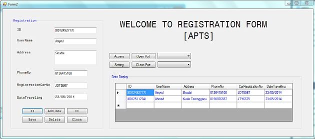
Webpage: www.ijaret.org                                                                  Volume 2, Issue X, Oct 2014
                                                                                              ISSN 2320-6802

             INTERNATIONAL JOURNAL FOR ADVANCE RESEARCH IN
                      ENGINEERING AND TECHNOLOGY
                                                    WINGS TO YOUR THOUGHTS…..
signal can penetrate to the heavy rain or haze. So              km/h) Automatic toll payment system can be
that, RFID technology required high performance                 implemented without toll gate. So that can reduce
rather than infrared that has been implemented in our           traffic congestion, especially during festival season.
country nowadays. RFID technology can be
commercialized in this particular industry to make              Acknowledgement
improvements for public convenience.                            The author would like to thank Universiti Teknikal
Based on frequency analysis that has been made, the             Malaysia Melaka (UTeM) for the fund to complete
frequency tagging for 3 and 5 meter occur more                  this research.
detection problem rather than 1 meter reading range.
Only certain frequency can make up to effective
                                                                REFERENCES
detection, which is 90% efficient. So that we can set
                                                                [1]    Aishah Binti Nordin, “Toll Payment
up the frequency at 5 meter range when implemented
                                                                       System,” Thesis of Universiti Teknikal
on toll booth. The installation process of this system
                                                                       Malaysia Melaka, May 2011.
need to consider another system involved, such as a
                                                                [2]    Mandeep Kaur, Manjeet Sandhu, Neeraj
plat image detector, video system, and speed control
                                                                       Mohan and Parvinder S.Sandhu, “RFID
system. So that the installation cost can increase the
                                                                       Technology       Principles,     Advantages,
amount of implementation. The maintenance of this
                                                                       Limitations     &      Its     Applications,”
project has to put into consideration also, the reader
                                                                       International Journal of Computer and
need to be checked frequently to make sure the
                                                                       Electrical Engineering, Vol. 3 (1), pp. 1793-
configuration is properly set up and no error
                                                                       8163, 2011.
detection during tagging operation.
                                                                [3]    Saurabh Vats, Gaurav Vats, Rahul
                                                                       Vaish, Varun Kumar, “Selection of
    6. CONCLUSION                                                      optimal electronic toll collection system for
This project sets out to design high performance and                   India: A subjective-fuzzy decision making
low cost automatic toll payment system in order to                     approach, Applied Soft Computing,” Vol.
make improvement to the current system that we are                     21, pp. 444–452, 2014
using now. The operating band of frequency is at                [4]    Pranoti Salunke, Poonam Malle, Kirti
902.4 MHz – 927.8 MHz, which is the user                               Datir, Jayshree Dukale, Automated Toll
bandwidth. The important parameter that has been                       Collection System Using RFID, IOSR
improved is range of detection, speed detection,                       Journal of Computer Engineering (IOSR-
frequency and times per tagging. The costing has                       JCE), Vol. 9 (2), pp. 61-66, 2013.
been reduced from roughly RM 80.00 without an ID                [5]    Khadijah Kamarulazizi, Dr.Widad Ismail ,
card to RM 0.50 with ID card. This is a big gap                        “Electronic Toll Collection System by
difference of costing based on passive tag RFID                        using Passive RFID Technology,” Journal
technology that can read up to 5 meters for effective                  of Theoretical and Applied Information
tagging distance. This system has the capability to                    Technology, pp. 70-76, 2010.
multi-tag per scan without line of sight (LoS)                  [6]    RS232 Data Interface, a Tutorial on Data
parameter. The signal can easily penetrate to the                      Interface and Cables”, ARC Electronics a
windshield of vehicles for data transfer purpose. A                    DCE Company, 2010, [Accessed: 30
specific database with the interface is act as software                August 2014].
on this system and this database operate the matching           [7]    M. H. A. Ilmudin, N. M. Z. Hashim, A. S.
ID process for the open or close gate at the plaza toll.               Ja’afar, A. Salleh, A. Jaafar, M. F. M.
The tag card at both entrance and exit point need to                   Sam, “Traffic Light Control System using
read and store the information in a database for                       434 MHz Radio Frequency,” International
transaction amount process. The overall project is a                   Journal     of    Research      in    Advent
success with high performance system and low cost                      Technology, Vol.2, No.8, pp. 26-31, 2014.
manufacturing and other expenses. In our future                 [8]    Mohamad Harris Misran, Meor Said,
work, we work on the implementation of PIC as                          Maizatul Alice, Azahari Salleh, Mohd
microcontroller to control the data from transponder                   Azlishah Othman, Mohd Muzafar Ismail,
to database via RS232 interface. Payment method can                    Hamzah Asyrani Sulaiman, Norbayah
be improved by doing additional system which is                        Yusop, Ridza Azri Ramlee Mai Mariam
GSM. Instead of using RFID card, SMS method can                        Mohamed, “RFID based Medical Database
be implemented as the user can receive a message                       System,” Australian Journal of Basic &
bills from expressway administration. Since the speed                  Applied Sciences, Vol 7 (12), 2013.
detection of the RFID system is higher, (up to 160

                                                       Page 7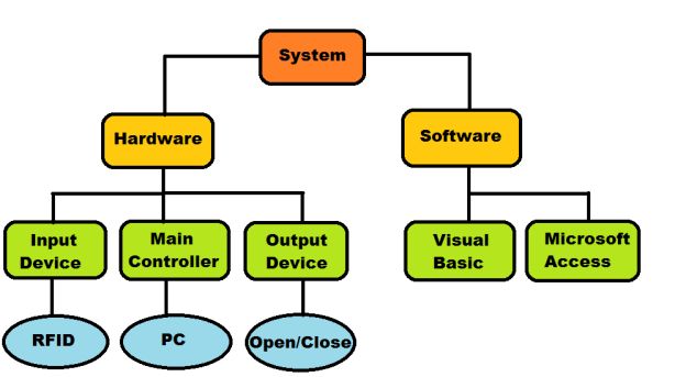
You can also read