Operation of a novel large area, high gain, single stage gaseous electron multiplier - IOPscience
←
→
Page content transcription
If your browser does not render page correctly, please read the page content below
Journal of Instrumentation

OPEN ACCESS

Operation of a novel large area, high gain, single stage gaseous electron
multiplier
To cite this article: F.D. Amaro et al 2021 JINST 16 P01033

View the article online for updates and enhancements.

 This content was downloaded from IP address 46.4.80.155 on 23/03/2021 at 09:03

Published by IOP Publishing for Sissa Medialab
 Received: October 30, 2020
 Accepted: December 4, 2020
 Published: January 27, 2021

Operation of a novel large area, high gain, single stage

 2021 JINST 16 P01033
gaseous electron multiplier

F.D. Amaro, ,1 R. Roque, N.V. Duarte, A. Cortez , and J.A. Mir
 LIBPhys — Coimbra University, Physics Department, University of Coimbra,
 3004-516 Coimbra, Portugal
 Gran Sasso Science Institute,

 L’Aquila, I-67100, Italy
 Istituto Nazionale di Fisica Nucleare, Laboratori Nazionali del Gran Sasso,

 Assergi, L’Aquila, I-67100, Italy

 E-mail: famaro@uc.pt

Abstract: The operation of a novel large area micro-patterned gaseous electron multiplier, made
from a 125 micron thick copper claded kapton foil, the COBRA_125, is presented. The CO-
BRA_125 is equiped with 3 independent electrodes which allow to establish 2 independent multi-
plication regions in a single micro-patterened gaseous electron mutiplier. We report on the operation
of a COBRA_125 with an active area of 100×100 mm2 . Charge gains above 104 and energy res-
olutions in the range 18%–20% were achieved in a mixture of Ar-CH4 (90%–10%) by irradiation
with X-rays from 55 Fe source. Gain and energy resolutions were stable over the detector area, with
maximum deviation from the average values of 8% and 15%, respectively.

Keywords: Gaseous detectors; Micropattern gaseous detectors (MSGC, GEM, THGEM,
RETHGEM, MHSP, MICROPIC, MICROMEGAS, InGrid, etc); Gaseous imaging and tracking
detectors

 1Corresponding author.

 c 2021 The Author(s). Published by IOP Publishing Ltd on behalf of
 Sissa Medialab. Original content from this work may be used under the
terms of the Creative Commons Attribution 4.0 licence. Any further distribution of this https://doi.org/10.1088/1748-0221/16/01/P01033
work must maintain attribution to the author(s) and the title of the work, journal citation
and DOI.
Contents

1 Introduction 1

2 The COBRA_125 3

3 Experimental setup 3
 3.1 COBRA_125 polarization 3
 3.2 Detector setup and data acquisition 4

 2021 JINST 16 P01033
4 Results 5
 4.1 Charge gain 5
 4.2 Energy resolution 6
 4.3 Uniformity 7

5 Conclusion 7

1 Introduction

High gain gaseous electron multipliers can be implemented by cascading several individual GEM
foils [1]. This is usually accomplished by using 2 or 3 foils stacked in a cascade, with separations
of few mm between each foil. The primary electrons resulting from the conversion of the incoming
radiation in the gas (or photoelectrons extracted from a photocathode in the case of Gaseous
Photomultipliers, GPM [2]) are amplified on the first GEM of the cascade, from which a fraction of
the resulting electrons are extracted and focused into the following GEM, in which the multiplication
process is repeated. Although high gains are achievable for several gas mixtures [2], the use of
cascaded GEM foils has however some inconveniences. On one hand, the maximum voltage
difference across the cascade increases with the addition of GEM foils to the cascade, and can
reach figures of the order of few kV [2, 3], which puts strain on the electrical connectors causing
applied voltage instabilities and leakage currents. In addition to the polarization of each of the
GEM foils, the voltage difference across the cascade also includes the necessary potentials to
establish the electric transfer field between each of the elements of the cascade. For instance, in
a 2-GEM detector, requiring a total polarization of 1.81 kV (excluding drift region), only 43%
of this voltage is used to directly polarize the GEM foils, in which the electron avalanches take
place, with the remaining being used to establish the electric fields in the transfer and induction
regions [4]. An optimization of the transfer field between GEMs of the cascade is also required,
which takes into account the inherent conflicting requirements between electron extraction from
the holes of one GEM and electron focusing into the holes of the next GEM [5]. As so, the
charge gain achievable with a cascade of GEM foils is far from the product of the individual
GEM gains. Another potential drawback is related with detector thickness; although the GEM foil
thicknesses are negligible, the gaps between consecutive GEMs are of few mm. This restricts their
implementation on applications requiring a few-millimetre thin sampling detectors such as Digital

 –1–
Hadron Calorimetry (DHCAL) [6]. To assure uniformity over the entire detector area, dictates the
constancy of the gaps within the cascade over the entire detector area, which is a challenge in the
production of large area GEM based detectors [7]. In addition, the larger distances travelled by the
electron clouds implies larger electron diffusion, which negatively impacts the achievable position
resolution and may be a problem for some applications [8, 9].
 High gain single element gaseous electrons multipliers such as the MHSP [10] or the THCO-
BRA [11] combine two independent multiplication regions in a single micro-patterned gaseous
electron multiplier (MPGD) and are an alternative to GEM cascades. These alternatives provide a
simple geometry which allows electron multiplication in a hole (similar to the one of GEM foils),
followed by a second multiplication stage in the same structure. For example, in the case of the

 2021 JINST 16 P01033
MHSP, the first gain element is the hole structure, followed by a Micro Strip Gas Chamber (MSGC)
like multiplication stage, with 2 independent sets of electrodes (figure 1, left). Whilst in the MHSP
these electrodes are linear, in the THCOBRA (figure 1, right) they are curved. In either case,
the holes cross the copper in the middle of the cathodes and the anodes are placed between two
consecutive cathodes. The electrons which are multiplied inside the holes are extracted and further
multiplied in the region between cathode and anode. The resulting charge is collected at the anodes.

 Figure 1. Detail photos of the MHSP (left) and THCOBRA (right) bottom sides.

 The above mentioned setup allows high gains in a single element since the multiplication region
at the holes is immediately followed by another, independent, multiplication stage.
 The main differences between THCOBRA and the MHSP are the insulating material used
between the two copper layers and their dimensions. THCOBRA uses a 400 micron thick G10 plate
whereas a 50 micron thick Kapton foil is used in the fabrication of the MHSP. While, thanks to
thick G10 plate, the THCOBRA is an extremely robust gaseous electron multiplier, it is not suitable
for operation in detectors with high purity requirements, such as noble gas sealed detectors, due
to the large outgassing and intrinsic radioactivity of the G10. THCOBRA elements also require
higher polarization voltages to achieve charge multiplication due to their larger thickness. On the
other hand, the MHSP, although sharing the same constituent materials and production techniques
as the GEM, was never implemented over large areas, due to the difficulty in the production of the
thin (10–20 micron wide) anode strips. The presence of the thin electrodes made it very prone to
damage caused by electrical discharges. As a consequence of these technical difficulties, it has been
impossible to implement a high gain, large area, robust, single element MPGD, compatible with
low-outgassing applications.

 –2–
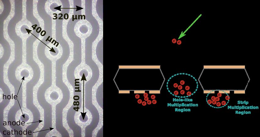
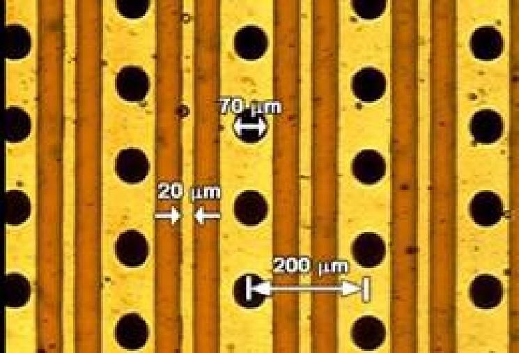
2021 JINST 16 P01033
Figure 2. (left) Micro-photography of the COBRA_125 bottom side. (right) Operating principle of the
COBRA_125; the primary electrons are drifted to the holes of the COBRA_125, where they experience a
first (hole like) multiplication stage, controlled by the voltage difference, VHOLE , between the top and cathode
electrodes. The resulting charge is then extracted from the holes and further multiplied in the region between
the cathodes and anodes, by means of the voltage between these two electrodes, VSTRIPS . The final charge is
collected at the anodes.

2 The COBRA_125

We have developed a novel MPGD which improves some issues of the MHSP; following the
experience with 100 micron Kapton thick GEM foils, which showed immunity to damaged caused by
discharges [12], we have implemented the COBRA_125, made from a 125 micron thick Kapton foil,
equipped with 60 micron wide electrodes (figure 2). The COBRA_125 used in these measurements
was produced at CERN workshops, with an active area of 10×10 cm2 . The bi-conical holes, with
larger and smaller diameters of 120 micron and 60 micron, are etched in a regular pattern on the
copper and Kapton. While the top side of the COBRA_125 is a continuous electrode (similar to the
one in GEM’s) the bottom side is equipped with 2 independents sets of electrodes (figure 2, left).
One of these (the cathodes), surrounds the holes while the other (anodes) are placed in between
each pair of consecutive cathodes, separated by a distance identical to their thickness (60 micron).

3 Experimental setup

3.1 COBRA_125 polarization
By applying a voltage difference, VHOLE , between the top (GEM-like) electrode and the cathode, an
electrical field is established inside the holes, responsible for the electron avalanches in this region.
The resulting charge is then extracted from the holes and further multiplied in the region between
the anode and the cathode due to an additional voltage difference, VSTRIPS , established between

 –3–
these two electrodes. The resulting charge is collected at the anodes of the COBRA_125. The total
voltage applied across the COBRA_125, VTOTAL , is the difference between the voltage applied to
the anodes and top electrodes, VANODE and VTOP , respectively.
 The induction mesh, located underneath the COBRA_125 in figure 2 is held at ground potential,
ensuring high electron collection efficiency into the anodes.
 Prior to its assembly in the detector, and after some hours at a temperature of 40◦ C under low
humidity conditions, the dark currents between top and cathodes and between cathodes and anodes
were measured and found to be, respectively, 2 nA and 5 nA, for VHOLE and VSTRIPS of 300 V.

3.2 Detector setup and data acquisition

 2021 JINST 16 P01033
The COBRA_125 was placed in a stainless steel chamber, equipped with high voltage and signal
feedthroughs. The chamber, with an inner volume of 20 × 20 × 5.5 cm3 , was sealed using a Viton
O-ring with a stainless steel plate (4 mm thick). Depending on the type of measurements made, in
current or pulse mode, the stainless steel plate was equipped either with a 12 × 12 cm2 aluminized
Mylar™ foil (25 μm thick) for the pulse mode measurements or with a 55 mm diameter, 4 mm
thick, fused silica window, for the current mode measurements. In this later mode of operation,
a 250 nm CsI photocathode was deposited on another fused silica window, pre-evaporated with a
100 Å aluminium layer, which was placed 9 mm away from the COBRA_125, replacing the drift
mesh depicted in the scheme of figure 2. In the pulse mode operation, the drift region, 9 mm deep,
was established by the top electrode of the COBRA_125 and the drift mesh (made from a 80 μm
diameter stainless-steel wire with 900 μm spacing), as depicted in figure 2.
 The detector was operated in a mixture of Ar-CH4 (90%–10%), continuously flowing through
the detector at a rate of 2 litres per hour. The pressure on the detector was maintained sligtly
above atmospheric pressure and the detector was seperated from the atmosphere by a small layer of
vacuum pump-oil where the gas exaust tube was submersed.
 The electrodes of the COBRA_125 were independently biased using CAEN N471A power
supplies. A ramp up rate of ∼5 V/sec was manually established for the polarization of the electrodes.
As a precaution, the maximum current on each channel was limited to 120 nA, to ensure protection
to the electrodes of the COBRA_125 in case of discharge.
 In the pulse mode operation the primary electron clouds were produced by conversion of
5.9 keV X-rays from a 55 Fe source. The K emission at 6.5 keV was attenuated with a Cr filter
placed between the source and the detector entrance window. The primary electron clouds were
focused into the holes of the COBRA_125 by an electric field, EDRIFT , established between the drift
mesh and the top electrode of the COBRA_125. The final electron clouds were collected at the
anodes of the COBRA_125 using a charge sensitive pre-amplifier (Canberra 2004) whose output
was fed to a linear amplifier (Tennelec 243) with peaking and shaping time constants of 2 and 4
microseconds, respectively. The signals from the linear amplifier were digitized by a 1024 channel
ADC (Nucleus PCA). For each dataset, acquired over a period of 120 seconds, a single Gaussian
curve was fitted to the main peak (figure 5). The median and spread of the Gaussian fit were used
in the energy resolution calculation and charge gain estimation, as a function of the applied voltage.
 Charge gain calibration was performed in current mode operation. The Mylar™ foil used as
entrance window for the X-ray‘ s in the pulse mode measurements was replaced by a fused silica
window and the discrete 55 Fe X-ray source by a pen-style continuous HgAr UV calibration lamp.

 –4–
The drift electrode in figure 2 was replaced by an additional fused silica window, vapor deposited
with a 250 nm CsI photocathode on top of a 100 Å layer of Al, which allowed an electric field,
EEXTR , to be established between the fused silica window and the top electrode of the COBRA_125.
EEXTR was responsible for the primary electron extraction from the CsI photocathode. Depending
on the electric field at the surface of the photocathode and on the UV lamp intensity, primary
currents of few tenths of pA were measured, for null electric fields across the holes and between
the strips of the COBRA_125. While EEXTR was kept constant throughout the measurements, the
UV lamp intensity was adjusted in order to keep the currents at the electrodes of the COBRA_125
below the limit set on the CAEN N471A power supplies (∼120 nA). In this mode of operation, the
charge gain is taken directly as the ratio of the current measured at the anodes of the COBRA_125

 2021 JINST 16 P01033
and the primary current emitted by the photocathode; both these currents were subtracted from
their dark values, i.e. the values measured without photocathode illumination. The current at the
photocathode was measured with an analog electrometer (Keithley 610C) while the anodes current
was determined by measuring the voltage drop across a 12 MΩ resistor, connected in series between
the anodes of the COBRA_125 and its corresponding power supply.

4 Results

4.1 Charge gain
Figure 3 presents the centroids of the pulse height distributions obtained by irradiating the CO-
BRA_125 with X-rays from a 55 Fe source, as a function of the VSTRIPS , (figure 3, left) and VHOLES
(figure 3, right). The charge gains, measured in current mode using the CsI photocathode and HgAr
lamp as described above, are also overlapped in figure 3 (left). The charge gains in pulse mode were
calibrated by normalizing the centroids of the Gaussian peaks in the pulse height distributions to
the gain obtained in current mode, for the same voltages applied to the COBRA_125. Maximum
gains above 104 were achieved for stable operating conditions (before the unset of discharges).

Figure 3. Charge gains achieved with COBRA_125 in Ar-CH4 (90–10), as a function of VSTRIPS (left) and
VHOLES (right), for different values of VHOLES and VSTRIPS , respectively. Maximum charge gains achieved
were 3×10⁴ in pulse mode (using the 55 Fe source). On the left, also presented are the charge gains in current
mode, recorded for matching voltages as the ones in pulse mode, and used for their calibration. The maximum
gain in current mode was 6×10⁴ .

 –5–
4.2 Energy resolution

Figure 4 presents the energy resolution (%FWHM) obtained by fitting a Gaussian to the centroids
of the pulse height distributions that have already been used to extract the charge gains in pulse
mode presented in figure 3.

 2021 JINST 16 P01033
Figure 4. Energy resolution achieved with the COBRA_125 in P10, as a function of VSTRIPS (left) and
VHOLES (right).

 In figure 5 we present an example of a typical pulse height distribution recorded with the
COBRA_125 by irradiation with the 55 Fe source. Clearly visible features are the full energy peak
(at 5.9 keV), the argon escape peak at 2.9 keV and the electronic noise, which in our setup was below
1 keV. The pulse height distribution features an energy resolution of 18.1% (5.9 keV, FWHM) and
a clear separation of the argon escape peak.

Figure 5. Typical pulse height distribution recorded with the COBRA_125 by irradiation with the 55 Fe

source for VHOLES = 630 V and VSTRIPS = 130 V. Acquisition time was 120 s.

 –6–
4.3 Uniformity
The results presented in the studies above were obtained by irradiating a small portion of the detector,
in its center. In order to evaluate the detector uniformity over its full sensitive area, a series of
100 measurements were performed with a collimated (∼.785 mm2 ) 55 Fe source, in a regular 10×10
matrix (10 mm spaced), uniformly covering the full 100×100 mm2 area of COBRA_125. For each
point, corresponding to a different (x,y) location, a 120 s dataset was taken, allowing to determine
the energy resolution and charge gain for that specific coordinate. The results are presented in
figure 6 and show that no region of the COBRA_125 presented a charge gain or energy resolution
deviation from the average values of more than 8% and 15%, respectively. The irradiation was

 2021 JINST 16 P01033
performed at moderated VTOTAL across the COBRA_125, to which corresponded an average charge
gain of 1.4×10³ and average energy resolution of 20.4%.
 The results shown in figure 6 represent an improvement in charge and gain uniformity across
the whole detector area when compared with previous studies made with cascades of 3-GEM
foils [13, 14].

Figure 6. Charge gain (left) and energy resolution (right) over the COBRA_125 area for VSTRIPS = 250 V
and VHOLES = 590 V. Acquisition time for each dataset was 120 s. Average energy resolution was 20.4%
and charge gain 1.4×10³ .

5 Conclusion

We presented the results of the operation of a novel gaseous electron multiplier, the COBRA_125.
This detector was fabricated with a 125 micron thick, copper cladded, Kapton foil and is equipped
with 3 independent sets of electrodes, which allow to establish 2 independent multiplication regions.
This novel configuration results in maximum gains of 3×10⁴ when irradiated by X-rays from a 55 Fe
source and operating in Ar-CH4 (90%-10%). This figure is equivalent to the gain reported in [1]
3.4×10⁴ , achieved in similar conditions, but using three GEM foils in cascade. Typical values of
energy resolution (%FWHM) recorded were found to be in the range 18%–22%. Operating the
COBRA_125 in current mode, with the primary electron being extracted from a reflective photo-
cathode irradiated by an ArHg UV lamp, result in gains slightly higher, 6.6×10⁴ , which in this case
are an order of magnitude lower than the ones achieved with a 3-GEM under similar conditions [2].

 –7–
The gain and energy resolution are fairly constant over the 100×100 mm2 of the COBRA_125,
with deviations not larger than 8% and 15%, respectively. This compares favorably with cascaded
GEM detectors: previous results of our investigations with a double GEM cascade [12] showed
gain and energy resolution variations of 10% and 20%, while in [13, 14] the lowest values of gain
and energy resolution variations with a 3-GEM detector, were 19% and 23%, respectively. This
improvement in the uniformity response with the COBRA_125 is attributed to the use of a single
element, without the need to maintain a uniform separation between individual GEM foils as it is
the case in 3-GEM detectors.
 Although not measured in this work, the use of a single amplification element should also

 2021 JINST 16 P01033
improve the electron diffusion, which is a desired trait in several applications in which position
resolution is important [8, 9]. Future work will include position resolution measurements with
a modified COBRA_125, which allows for 2D position determination by charge division with a
resistive line [15].

Acknowledgments

Support is acknowledged under the research projects PTDC/NAN-MAT/30178/2017 and
CERN/FIS-INS/0025/2017, funded by national funds through FCT/MCTES and co-financed by
the European Regional Development Fund (ERDF) through the Portuguese Operational Program
for Competitiveness and Internationalization, COMPETE 2020. N.F.V.D. and R.R. acknowledge the
support of FCT, under contracts PD/BD/128268/2016 and SFRH/BD/143355/2019, respectively.

References

 [1] F. Sauli, The gas electron multiplier (GEM): Operating principles and applications, Nucl. Instrum.
 Meth. A 805 (2016) 2.
 [2] A. Buzulutskov, L.I. Shekhtman, A. Breskin, R. Chechik, G. Garty and F. Sauli, The GEM
 photomultiplier operated with noble gas mixtures, Nucl. Instrum. Meth. A 443 (2000) 164.
 [3] R. Venditti, Characterization of triple-GEM detectors for the Phase I Muon System Upgrade of the
 CMS Experiment at LHC, in 7th IEEE International Workshop on Advances in Sensors and Interfaces
 (IWASI 2017), Vieste, Italy, 15–16 June 2017 [DOI].
 [4] H. Sako et al., Development of a prototype GEM TPC with a gating grid for an H-dibaryon search
 experiment at J-PARC, Nucl. Instrum. Meth. A 763 (2014) 65.
 [5] D. Mörmann, Study of novel gaseous photomultipliers for UV and visible light, Ph.D. Thesis,
 Weizmann Institute, Israel (2005).
 [6] S. Bressler et al., Novel Resistive-Plate WELL sampling element for (S)DHCAL, Nucl. Instrum. Meth.
 A 958 (2020) 162861.
 [7] D. Abbaneo et al., Status of the Triple-GEM project for the upgrade of the CMS Muon System, 2013
 JINST 8 C12031.
 [8] NEXT collaboration, Electroluminescence TPCs at the Thermal Diffusion Limit, JHEP 01 (2019) 027
 [arXiv:1806.05891].

 –8–
[9] G. Mazzitelli et al., MPGD Optical Read Out for Directional Dark Matter Search, in 2018 IEEE
 Nuclear Science Symposium and Medical Imaging Conference, pp. 1–4 (2018) [DOI]
 [arXiv:1901.04192].
[10] J.F.C.A. Veloso, J.M.F. dos Santos and C.A.N. Conde, A proposed new microstructure for gas
 radiation detectors: The microhole and strip plate, Rev. Sci. Instrum. 71 (2000) 2371.
[11] F.D. Amaro, C. Santos, J.F.C.A. Veloso, A. Breskin, R. Chechik and J.M.F. dos Santos, The
 Thick-COBRA: A New Gaseous Electron Multiplier for Radiation Detectors, 2010 JINST 5 P10002
 [arXiv:1008.0830].
[12] F.D. Amaro et al., A robust large area x-ray imaging system based on 100 μm thick Gas Electron
 Multiplier, 2015 JINST 10 C12005.

 2021 JINST 16 P01033
[13] R.N. Patra, R.N. Singaraju, S. Biswas, Z. Ahammed, T.K. Nayak and Y.P. Viyogi, Measurement of
 basic characteristics and gain uniformity of a triple GEM detector, Nucl. Instrum. Meth. A 862 (2017)
 25 [Erratum ibid. 905 (2018) 199] [arXiv:1705.03849].
[14] S. Chatterjee et al., Study of uniformity of characteristics over the surface for triple GEM detector,
 Nucl. Instrum. Meth. A 936 (2019) 491 [arXiv:1807.04961].
[15] A. Silva, C.D.R. Azevedo, L. Carramate, T. Lopes, R. De Oliveira and J.F.C.A. Veloso, X-ray imaging
 detector based on a 2D sensitive THCOBRA with resistive line readout, IEE Nucl. Sci. Symp. Med.
 Imag. Conf. (2012) 1160.

 –9–
You can also read