The SMILE Soft X-ray Imager (SXI) CCD design and development - The SMILE Soft X-ray Imager (SXI) CCD design and ...
←
→
Page content transcription
If your browser does not render page correctly, please read the page content below
The SMILE Soft X-ray Imager (SXI) CCD design and
development

M. R. Somana,*, D. J. Halla, A. D. Hollanda, R. Burgona, T. Buggeya, J. Skottfelta,
S. Sembayb, P. Drummb, J. Thornhillb, A. Readb, J. Sykesb, D. Waltonc,
G. Branduardi-Raymontc, T. Kennedyc, W. Raabd, P. Verhoeved, D. Agnolond and
C. Woffindene
    a
      The Open University, Walton Hall, Milton Keynes, MK7 6AA, UK
    b
      University of Leicester, Leicester, LE1 7RH, UK
    c
      Mullard Space Science Laboratory, University College London, Surrey, RH5 6NT, UK
    d
      Directorate of Science of the European Space Agency, ESTEC, 2201 AZ, Noordwijk, The Netherlands
    e
      Teledyne-e2v, Chelmsford, Essex, CM1 2QU

        E-mail: matthew.soman@open.ac.uk

ABSTRACT: SMILE, the Solar wind Magnetosphere Ionosphere Link Explorer, is a joint science
mission between the European Space Agency and the Chinese Academy of Sciences. The
spacecraft will be uniquely equipped to study the interaction between the Earth’s
magnetosphere-ionosphere system and the solar wind on a global scale. SMILE’s instruments
will explore this science through imaging of the solar wind charge exchange soft X-ray
emission from the dayside magnetosheath, simultaneous imaging of the UV northern aurora and
in-situ monitoring of the solar wind and magnetosheath plasma and magnetic field conditions.
The Soft X-ray Imager (SXI) is the instrument being designed to observe X-ray photons emitted
by the solar wind charge exchange process at photon energies between 200 eV and 2000 eV.
X-rays will be collected using a focal plane array of two custom-designed CCDs, each
consisting of 18 µm square pixels in a 4510 by 4510 array.
SMILE will be placed in a highly elliptical polar orbit, passing in and out of the Earth’s
radiation belts every 48 hours. Radiation damage accumulated in the CCDs during the mission’s
nominal 3-year lifetime will degrade their performance (such as through decreases in charge
transfer efficiency), negatively impacting the instrument’s ability to detect low energy X-rays
incident on the regions of the CCD image area furthest from the detector outputs. The design of
the SMILE-SXI CCDs is presented here, including features and operating methods for
mitigating the effects of radiation damage and expected end of life CCD performance.
Measurements with a PLATO device that has not been designed for soft X-ray signal levels
indicate a temperature-dependent transfer efficiency performance varying between 5x10⁻⁵ and
9x10⁻⁴ at expected End of Life for 5.9 keV photons, giving an initial set of measurements from
which to extrapolate the performance of the SXI CCDs.

KEYWORDS: X-ray detectors and telescopes; Space instrumentation; Solid State Detectors;
X-ray detectors.

*
    Corresponding author.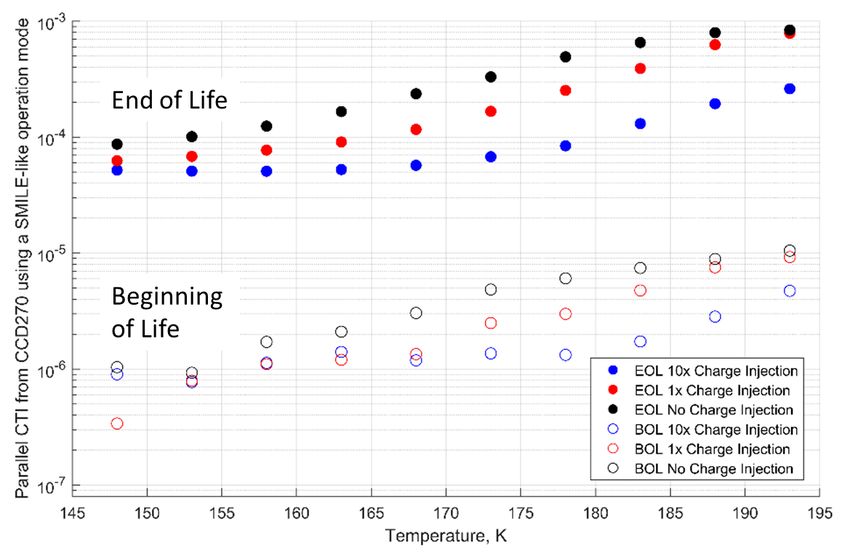
Contents

1. Solar wind Magnetosphere Ionosphere Link Explorer (SMILE)                                 1
  1.1 Soft X-ray Imager (SXI)                                                                1
2. The CCD370                                                                                3
  2.1 Design heritage                                                                        3
  2.2 CCD optimisation for soft X-ray detection                                              3
  2.3 CCD370 operation for soft X-ray photon counting                                        5
3. Predicting the performance of the CCD370s                                                 6
  3.1 X-rays with On-Chip Pixel Binning                                                      6
  3.2 CTI of a PLATO CCD270 with SMILE-like clocking                                         7
4. Conclusions and further work                                                              8

1. Solar wind Magnetosphere Ionosphere Link Explorer (SMILE)
SMILE, the Solar wind Magnetosphere Ionosphere Link Explorer, is a small class joint venture
mission between the European Space Agency and the Chinese Academy of Sciences [1]. With a
planned launch date of late 2021, SMILE will be in a unique position to observe the dynamic
response of the Earth’s magnetosphere to the solar wind impact using an instrument suite made
up of the Soft X-ray Imager (SXI), the Ultra-Violet Imager (UVI), and in-situ monitoring
provided by a Light Ion Analyser (LIA) and a MAGnetometer (MAG).
The highly elliptical polar orbit will allow SMILE to perform simultaneous observations of soft
X-ray emissions from the interaction between the solar wind and the Earth’s dayside
magnetosheath, and UV excitations in the Northern hemisphere’s aurora over a ~48 hour orbital
period. SMILE will collect data over a 3-year mission period to further the understanding of
how space weather can influence the Earth’s magnetosphere and ionosphere.
1.1 Soft X-ray Imager (SXI)
The Soft X-ray Imager (SXI) is one of the primary instruments on SMILE, optimised to photon
count over the 200 eV to 2000 eV energy range with a wide field of view (see Table 1). The
instrument is designed to image X-rays produced by the process called Solar Wind Charge
eXchange (SWCX) [2,3], where photons are emitted from interactions of ions in the solar wind
with neutral geocoronal atoms. Earth’s SWCX occurs primarily at the boundary of the Earth’s
magnetopause, and the imager will provide a semi-continuous observation with a time
resolution on the order of minutes to monitor its location.
A mechanical drawing of the SXI instrument design is shown in Figure 1. Silicon Micro-Pore
Optics (MPOs) arranged in a lobster-eye configuration are used to focus the X-rays onto a focal
plane of two large-area Charge-Coupled Devices (CCDs) where the X-rays are directly
detected. CCD operation and initial image processing are carried out in the Front End

                                                  –1–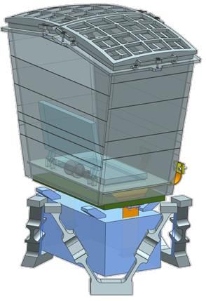
Electronics (FEE) located under the focal plane, and overall instrument control and
collation/compression of the data takes place in the Data Processing Unit (DPU) positioned
away from the instrument in the payload module. A large optical baffle is designed to shield the
focal plane from stray light (primarily from the Sun and the Earth) and a thermal radiator is used
as a passive heat dissipater to reduce the focal plane temperature to below -100 ˚C. A door in
front of the focal plane will be closed as the spacecraft approaches perigee to shield the CCDs
from the higher levels of radiation found in the trapped belts.
                         Table 1. Specifications of the Soft X-ray Imager.

                              Characteristic            Units      Value
                                                                   26.5° x
                               Field of view           degrees
                                                                    15.5°
                                Focal length             cm           30
                        Primary science energy range     eV       200-2000
                              Instrument mass            kg          ~26
                                Optics mass              kg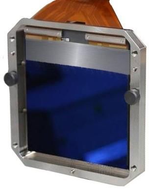
2. The CCD370
2.1 Design heritage
The SXI CCDs have been developed to optimise soft X-ray sensitivity throughout the mission
lifetime, whilst adopting space-qualified designs and processes from other developments. The
CCDs are manufactured by Teledyne-e2v with a design adapted from the PLATO CCD270s [4],
so that the qualification of the mechanical and electrical interfaces can be adopted (Figure 2).
For example, the silicon carbide packaging, the wire-bonded flex circuitry for the electrical
interface, and the package-mounted temperature sensor, will all have been qualified as part of
the PLATO programme, so the cost and schedule are reduced for SMILE.
The SXI CCD uses the same electrical interface as the PLATO CCDs, therefore test cameras
and procedures for Teledyne-e2v testing can be adopted, and the CCD flight drive electronics
can be an adaptation of the PLATO ‘slow camera’ readout electronics, both provided by
collaborative partners from UCL’s Mullard Space Science Laboratory.

  Figure 2. An artist’s impression of the SMILE CCD370, with a greyed-out store region across
    approximately 1/7 of the silicon area. The electrical interface is made through a flex-circuit
wire-bonded to the edge of the sensor adjacent to the serial register. A temporary acrylic window is
        visible in front of the device here, which is part of its travelling and handling jig.

2.2 CCD optimisation for soft X-ray detection
The PLATO CCD270 was designed for the mission’s goals of optical imaging with large signal
levels. To optimise the device for the SXI application, modifications have been made at the
silicon level to maximise the X-ray detection efficiency, at both the beginning and end of
operational life. The SMILE SXI CCD is designated as the CCD370. Details of the CCD design
and performance are shown in Table 2 and an artist’s impression of the device is illustrated in
Figure 2.

                                               –3–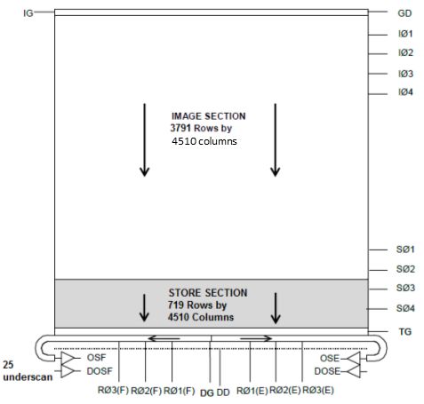
The detection efficiency for the SXI CCDs is maximised by using back-illuminated and
uncoated silicon, with an enhanced passivation process on the back-surface, which has been
shown to maximise the quantum efficiency in the soft X-ray range [5].
 Table 2. Design parameters of the CCD370 for the Soft X-ray Imager. The split ratio of the image
       and store areas is subject to change in the final design, but will be approximately 6:1.

                     Property                 Units                  Value
             Sensitive silicon thickness       µm                      16
                 Native pixel size          µm x µm                  18x18
                  Image area size             pixels       4510 columns x 3791 rows
                                            mm x mm              81.18 x 68.24
                  Store area size             pixels        4510 columns x 719 rows
                   Responsivity            µV electron-1              ~7
                   Output nodes                 -                      2
                  Serial registers              -                      1

Throughout the nominal 3 year mission lifetime, the CCDs will experience radiation damage,
primarily from trapped and solar protons [6]. The damage from the protons in Earth’s radiation
belts will be limited by closing the shield door when close to Earth, but loss of performance is
still expected in the form of lattice damage to the silicon. Traps formed by lattice damage in the
buried channel of the sensor can capture electron(s) whilst the signal is transferred through the
detector, and release it at a later time into a different pixel, reducing the efficiency of the
transfer of charge through the detector (Charge Transfer Inefficiency, CTI).
At the low end of the primary science energy band, 200 eV X-rays are expected to generate on
average approximately 55 electrons. At these low signal levels, degradation in CTI through the
mission lifetime can have a significant effect on the number of electrons from an X-ray that are
transferred across the ~8 cm sensor to be converted to a voltage at the output node. The CTI has
been maximised for low signals by including a Supplementary Buried Channel (SBC) in the
parallel region of the sensor, and narrowing the channel in the serial register. The SBC takes
heritage from Gaia [7], and improves the CTI by reducing the volume of silicon that the small
charge packets occupy, therefore minimising the number of traps that the signal electrons
encounter [8]. Other methods such as optimised clocking schemes [9] and multi-level clocking
will also be considered to maximise performance [10].
To improve the signal to noise ratio at low signal levels, the output amplifier has been modified
to increase the responsivity from ~2 µV/e to ~7 µV/e, by adopting a design with heritage in the
Euclid CCDs. The high signal handling capacity of the PLATO output is not required, therefore
the improved responsivity will allow lower signal levels to be observed above a threshold set by
the readout noise.

                                                –4–
Figure 3. Schematic layout of the SMILE SXI CCD370.
2.3 CCD370 operation for soft X-ray photon counting
Soft X-rays in a 16 µm thick back-illuminated CCD primarily interact in the field-free region at
the back surface. Assuming there is no recombination at the back surface, signal electrons are
only collected in pixels after they have diffused from their point of generation to the depleted
region closer to the front surface. During this process, electrons can move laterally in the CCD
and may end up being collected in neighbouring pixels. To recombine signal collected in
adjacent pixels for a single X-ray, SXI will operate primarily in a 6×6 binning mode, meaning
the majority of X-rays will have their signal recombined in the output node and the signal to
noise will be maximised.
The throughput of the SXI CCDs is maximised by using a frame transfer operation allowing an
image to be integrated whilst the previous image is being read out. The transfer to exposure time
will be maintained at a ratio of greater than 1:10 to minimise any out of time events. In the 6×6
binning mode, the store region can be 1/7 of the total area of the CCD (Figure 3), which
improves the usable imaging area relative to the standard 1:1 image to store area ratio. The store
section will have separate parallel clocks, and will be mechanically shielded to prevent
illumination.
To negate the effects of radiation damage, the CTI can be improved by ensuring that any traps
with very slow release times (longer than the integration plus readout time) are filled before
signal packets are passed through the trap. This can be achieved by injecting signal as a line in
the top of the parallel register, interspersed through the image. The lines of charge injection
have been shown to improve the CTI performance (Section 3) but a trade-off is required: image
area is lost to the charge injection rows; and signal released from traps originally filled by the
charge injection increases the background noise in the rest of the frame. The effect of charge
injection on the CTI is discussed in the Section 3.2.
–5–3. Predicting the performance of the CCD370s
To inform the design decisions for the SXI CCD370s, data was collected with a PLATO device,
the CCD270-11363-20-01 using a cryostat camera at ESTEC. Part of the image area of one
node has been irradiated with 6.5 × 10⁹ protons cm-2 (10 MeV equivalent), allowing the
performance at approximate SXI Beginning Of Life (BOL) and End Of Life (EOL) levels to be
assessed from different regions of the image area (Figure 4). The nominal EOL level for the SXI
CCDs is likely to be adjusted from this value as a result of future instrument design optimisation
and spacecraft environment modelling, but this irradiation fluence provides a baseline for
performance and could be scaled accordingly.
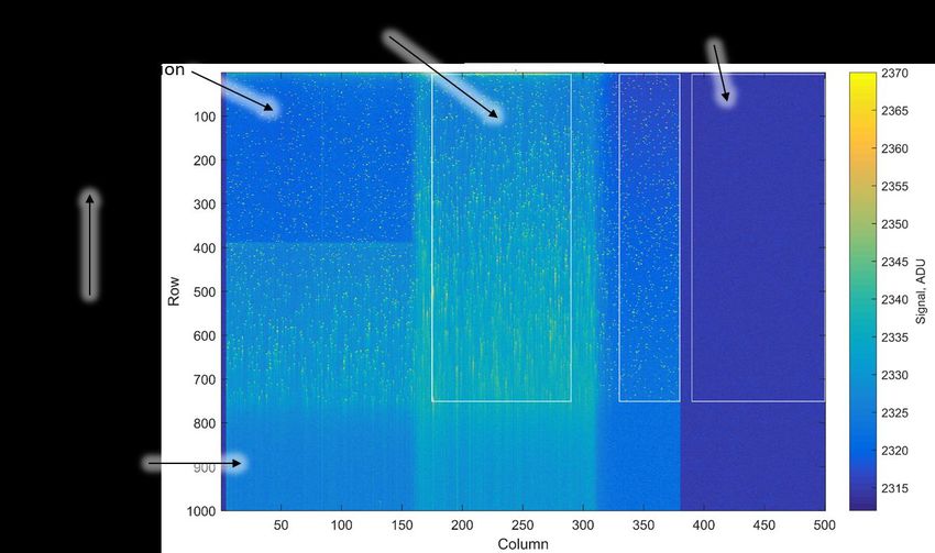
Figure 4. Binned readout from one node of a PLATO CCD270, which has had regions irradiated
with protons. This image was recorded with exposure to a 55Fe source, with the detector at 207 K.
3.1 X-rays with On-Chip Pixel Binning
The standard laboratory X-ray source, Iron-55 (55Fe) was used with an exposure time of 0.5 s
and resulting flux of approximately 1 X-ray per 3600 native pixels (or 1 X-ray per 100 binned
6×6 pixels). The X-ray events are observed as localised regions of bright pixels in Figure 4. By
analysing X-rays observed in the unirradiated section of the detector, the result of pixel binning
can be studied.
The pixel output from the average X-ray event is calculated, with the result shown in Figure 5.
As expected, more significant charge sharing is observed when no binning is applied. The
background noise was calculated to be 5.3 and 5.4 electrons rms for the unbinned and binned
cases respectively. A threshold was used, and the number of pixels above this threshold was
calculated for each event. The resulting distributions are shown in Figure 5c and Figure 5d, for a
threshold of 4.5× the background noise (chosen to identify pixels which have a signal level
clearly above the noise floor). When binning is applied, the majority of these 55Fe (~6 keV)
–6–events shift from being 2-pixel events to single pixel events. The 2-pixel events that remain
when binned are usually identified as the result of poor CTI in the un-optimised serial clocking
pattern used for this initial test. Soft X-rays will have shorter attenuation lengths that those
generated by 55Fe, and therefore are more likely to be split across multiple pixels and the benefit
of binning will be even more pronounced.
Figure 5. 6×6 pixel binning confines the majority of X-ray events to one or two pixels. The average
X-ray event observed in the unirradiated region of interest at 148 K is seen to have signal split into
neighbouring pixels when not binned (a), but confined to a single pixel when binned (b). The
number of pixels above a threshold (4.5× the background noise) for each of the binning modes also
shows the shift of multi-pixel events when not binning (c) to primarily 1 or 2 pixel events when
binning is applied (d).
3.2 CTI of a PLATO CCD270 with SMILE-like clocking
The CTI has also been measured using the 55Fe events observed in the PLATO device. A
SMILE-like clocking scheme was devised using a (binned) pixel readout rate of 100 kHz and a
line shift time of 22.6 µs. The energy of single-pixel X-ray events was studied as a function of
row position to determine the average charge loss per transfer, for images recorded at a range of
temperatures. Regions of interest selected from the unirradiated and irradiated areas of the
detector allowed the performance at the BOL and EOL to be compared.
To investigate the effects of charge injection, lines of approximately 5000 electrons signal level
(measured at 163 K) were injected at regular intervals throughout the frame. The parallel CTI as
a function of temperature is shown in Figure 6, for three different cases: no charge injection; a
–7–single charge injection line at the beginning of the image; and a charge injection line every 450
native pixels (10 per image).
Parallel CTI degrades by ~2 orders of magnitude following the approximately EOL equivalent
proton irradiation level, and generally the CTI is better at lower temperatures. Charge injection
is shown to improve the CTI performance, and essentially delay the onset of CTI degradation to
a warmer temperature. Charge injection may therefore be used to negate the loss of CTI
performance throughout the mission timeline, or to meet a CTI performance specification at a
warmer CCD temperature. Charge injection does result in a loss of usable image area, an
increase in image background noise and therefore its use will be a compromise in performance
parameters.
Figure 6. Parallel CTI performance of a PLATO CCD270 operated in SMILE-like conditions (6x6
binning and timing). The parallel CTI is defined as the proportion of signal lost per native pixel
transfer.
4. Conclusions and further work
The results presented here, made using a PLATO CCD270 sensor, provide a reference set of
measurements from which to predict if the performance of the SMILE CCD370s will be
sufficient to meet the science requirements of the mission. However, the prediction must be
extrapolated by taking into account many factors including: the X-ray signal levels of interest
during the mission are much smaller than the 5.9 keV X-rays measured here; the EOL fluence
levels on the SXI CCDs must be more accurately modelled using the latest information about
the orbit, spacecraft shielding and radiation environment; the improvements to the device
architecture such as the supplementary buried channel in the parallel region are predicted to
improve the CTI for small signal level charge packets; the readout clocking scheme of the
CCDs will be studied in detail and optimised where possible; and during the mission the CCDs
–8–will be irradiated cold, rather than in room temperature conditions, and therefore the trap
landscape may different. These considerations are being modelled to predict the expected EOL
science performance of the SXI CCDs, but the models cannot be verified until measurements
are made with the manufactured devices.
The SMILE SXI CCDs have been developed from heritage designs taking elements from
PLATO, Gaia and Euclid CCDs. However, the SXI devices (CCD370s) have been optimised for
their soft X-ray detection performance with modifications to the back surface treatment, image
to store region layout, parallel and serial channels and an increased responsivity output
amplifier. Readout with 6×6 native pixel binning will improve the energy resolution and low
X-ray energy sensitivity of the detectors, whilst also helping to negate against some poor CTI
effects.
The first CCD370s, and their smaller test-device counterparts the CCD380s, are expected to be
available for testing in early 2019, and will undergo both radiation damage testing and
calibration with soft X-ray sources. Readout timing and operation schemes will be optimised for
maximising the soft X-ray sensitivity across the entire image up to and beyond the EOL. After
launch in 2021, the SMILE spacecraft will allow scientists across the ESA-CAS collaboration to
monitor the magnetosphere’s dynamic response to the solar wind and further our understanding
of how space weather contributes to the workings of our solar system.
Acknowledgments
The authors would like to thank staff of the Payload Technology Validation section (Future
Missions Office at ESA’s Directorate of Science) for enabling and performing the
measurements and proving the test data into this study for the SMILE programme.
References
[1] W. Raab et al., SMILE: A joint ESA/CAS mission to investigate the interaction between the
solar wind and Earth’s magnetosphere, Proc. SPIE 9905, Space Telescopes and
Instrumentation 2016: Ultraviolet to Gamma Ray, 990502 (2016).
doi:10.1117/12.2231984.
[2] K. Dennerl et al., Solar system X-rays from charge exchange processes, Astronomische
Nachrichten 333 (2012) 324. doi:10.1002/asna.201211663.
[3] B. Walsh et al., Wide field-of-view soft X-ray imaging for solar wind magnetosphere
interactions, Journal of Geophysical Research, 121 (2016) 3353-3361
[4] J. Endicott, et al., Charge-coupled devices for the ESA PLATO M-class Mission, Proc. of
SPIE 8453 (2012).
[5] I. Moody et al., CCD QE in the Soft X-ray Range, Teledyne-e2v White Paper (14 March
2017).
[6] A. Holland et al., Techniques for minimizing space proton damage in scientific charge
coupled devices, IEEE Transactions on Nuclear Science 38 (1991) 1663.
–9–[7] G. M. Seabroke, et al., Digging supplementary buried channels: investigating the notch
architecture within the CCD pixels on ESA's Gaia satellite, Monthly Notices of the Royal
Astronomical Society 430.4 (2013) 3155-3170.
[8] A. Clarke, et al., Modelling charge storage in Euclid CCD structures, JINST 7 (2012)
C01058.
[9] D. J. Hall, et al., Optimisation of device clocking schemes to minimise the effects of
radiation damage in charge-coupled devices, IEEE Transactions on Electron Devices 59
(2012) 1099.
[10] N. J. Murray, et al., Multi-level parallel clocking of CCDs for: improving charge transfer
efficiency, clearing persistence, clocked anti-blooming, and generating low-noise
backgrounds for pumping, Proc. SPIE 8860, UV/Optical/IR Space Telescopes and
Instruments: Innovative Technologies and Concepts VI, 886020 (2013).
– 10 –You can also read