SEISMIC RETROFIT OF AN UNDERGROUND RESERVOIR
←
→
Page content transcription
If your browser does not render page correctly, please read the page content below
SEISMIC RETROFIT OF AN UNDERGROUND RESERVOIR

                                     Robert Small 1, Rob Jameson 2

ABSTRACT

        Seismic Upgrade of the University Mound Reservoir North Basin included 542
micropiles with 1335 KN (300 kip) design capacity installed in restricted overhead
conditions. The North Basin Reservoir is a 200,000 M3 (53 million gallon)
underground water reservoir which stores water for emergency or life safety
situations. This paper presents a case history of micropile installation for the seismic
retrofit project, highlighting the solutions employed to create drilling access and
detailing the unique load testing requirements and performance.
        Micropiles were installed on the reservoir side slopes to provide foundations
for new shears walls located around the site perimeter. The 200 mm (8 in) diameter
piles were installed using cased rotary drilling methods to advance through fill
embankments and then bonded in dense clayey sand of the Colma formation. Along
the southern edge of the site, pile bond zones encountered variable lengths of the
Franciscan rock formation. The micropiles were reinforced with double-corrosion
protected all-thread bar and all piles were post-grouted.
        All 542 piles were tested in tension to 1780 KN (400 kips) with acceptance
based on the FHWA (1999) criteria of evaluating actual apparent free lengths and
creep data. This approach is typically applied to ground anchor applications and
contrasts with the lower percentage of testing and load-deflection performance
measures commonly employed for micropiles. The extensive data set from
University Mound allowed for detailed comparison of performance tests, particularly
across the east side of the reservoir, which contained variable fill depths and
micropiles bonded into both Colma Sand and Franciscan Rock.
         Another unique challenge to this project was the access. All micropiles were
located on the reservoir’s 18 degree sideslope. Temporary platforms provided a
stable working area for the drill rig and workers, and were continually moved around
the site to create access as drilling progressed. In addition to the sloped condition,
the reservoir roof limited overhead clearance down to a limiting condition of 2.3 M
(7.5 ft) headroom. Detailed work sequencing and co-ordination with the excavation
and demolition contractors was required to ensure drill rig could access each work
location, with the corners providing specific challenge due to their dual camber.
        This was a challenging project due to the large pile quantity, high capacity and
limited headroom. However the requirements for testing of every pile, coupled with
working on an 18 degree slope were particularly unique elements of this work.

BACKGROUND

       University Mound North Basin Reservoir is located in San Francisco,
California. This reservoir was originally constructed in 1885 and provides an off-line
water storage facility within city limits. The San Francisco water supply originates in
the Sierra Nevada Mountains and is conveyed almost entirely by gravity for 320 KM
(200 miles) through a complex system of pipelines, tunnels, reservoirs and treatment
plants. The route crosses three major active faults – the Calaveras, Hayward and
San Andreas. In order to accommodate this challenging seismic environment, the
water supply system includes a number of off-line reservoirs and includes built-in
1
    Project Engineer, Malcolm Drilling Company, Inc., Hayward, CA, USA P: 510‐780‐9181 RSmall@MalcolmDrilling.com
2
    Project Manager, Malcolm Drilling Company, Inc., Hayward, CA, USA P: 510‐780‐9181 RJameson@MalcolmDrilling.com
                                                            1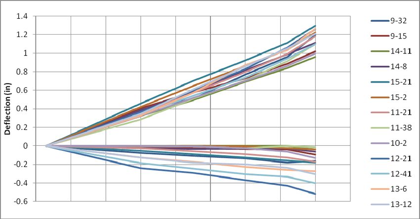
redundancy through parallel conveyance lines. University Mound North Basin is one
of 80 projects performed under San Francisco Public Utility Commission’s $4.6
Billion Water System Improvement Program which upgrades the service and seismic
safety of the City water supply.
        The reservoir is located in the south-eastern corner of the city and was
constructed on a slope using excavation on the south and west sides, combined with
embankment fill on the northeast corner. The perimeter embankment was raised 1.8
M (6 ft) in 1924, and subsequently a roof was added in 1962 and concrete lining
installed to improve containment and water quality. The reservoir is 229 M (750 ft)
from north to south and 168 M (550 ft) from east to west and has 200,000 M3 (53
million gallon) capacity. The reservoir sides slope from El. 51.1 M (167.6 ft) down to
invert at 44.5 M (145.9 ft) at a grade of 33%. The reservoir floor is nominally level.

SUBSURFACE CONDITIONS

       In general subsurface conditions can be described as fill, overlying native
clayey and silty sand, in turn overlying bedrock. However, due to the reservoirs large
size and location on a slope, the relative depth and thickness of these strata vary
widely across the site. Figure 1 shows a plan layout.

                       Figure 1. University Mound Plan Layout

       The native ground slopes from south to northeast across the site. The existing
grade is at El. 52.7 M (173 ft) in southwest corner, sloping down to El. 45.4 M (149 ft)

                                           2
at northeast, with a corresponding 7.3 M (24 ft) high embankment fill placed to
contain the reservoir. The shallowest bedrock was observed at El. 46.6 M (153 ft) in
the southeast corner, and sloped northwards to El. 6.1 M (20 ft) at northeast corner.
Borings along west side extended down to El. 39.6 M (130 ft) but did not encounter
rock.
Embankment fills, up to 7.3 M (24 ft) were placed to contain the east and
north sides of the reservoir. The greatest fill depth occurs at northeast corner, and
thickness tapers both south and west from this location. The fill materials are similar
to the native soils, comprising medium dense to dense silty sand and sandy clay,
with traces of gravel. SPT ‘N’ values in the fills were typically 20 to 40 blows / ft.
Medium dense to very dense sandy soils of the Colma Formation (Quaternary
Period - Pleistocene Age) are present throughout the site. The Colma ranges from
clayey to silty sand, and strength increases with depth. An upper zone of medium
dense material ranges from 1.5 to 6 M (5 to 20 ft) thickness, with typically SPT ‘N’
values of 15 to 25. The underlying Colma Formation is dense to very dense material,
with ‘N’ values exceeding 50, and based on triaxial testing indicates friction angle of
31 to 35 degrees, and cohesion of 24 kPa (500 psf).
Bedrock at the site is comprised of the Franciscan Formation (Late Jurassic
and Early Cretaceous). This complex unit is a tectonic mélange consisting primarily
of sandstone (greywacke) and shale, with mafic volcanic rocks and occurrences of
serpentinite. The relatively young rock has been subject to intense shearing and
deformation from regional seismic activity. The Franciscan composition and
engineering properties are extremely variable and within this project site exhibited
behavior ranging between that indicative of dense clayey gravel and hard,
moderately fractured rock. The project investigation borings were typically terminated
a maximum of 3 M (10 ft) into rock, where encountered, and described the
Franciscan as Basalt; intensely to closely fractured, moderate to deeply weathered
and ranging from weak to moderately hard. SPT ‘N’ values ranging from 64 to 148
were recorded in this zone. Rock strength testing was not performed or reported.
A monitoring well at the northeast corner of the site recorded groundwater
levels between El. 36.6 and 38 M (120 and 125 ft), and some groundwater was
observed perched on top of rock in the southeast corner during investigation.
RETROFIT SCHEME
The University Mound Seismic Upgrade aimed to preserve the integrity of
critical water supplies in the event of a severe earthquake. The primary concern was
the roof and its supporting columns, located on a 7.6 M (25 ft) grid across this site.
The structural upgrade involved two key elements; reinforced concrete floor to ceiling
shear walls connecting existing columns on the reservoir side slopes in radial and
circumferential orientations which were founded on micropiles, and two 60 M (200 ft)
square stainless steel brace frames that were constructed on the reservoir floor
using grade beam foundations. The balance of this paper is focused on the micropile
foundation system constructed on the side slopes.
A total of 542 micropiles were required for the retrofit program. All piles were
designed for a 1335 KN (300 kip) seismic load, applicable in both tension and
compression. The piles were designed by the owner as 57 mm (2.25 in) Gr150
threadbar only piles, with minimum 3 M (10 ft) unbonded length. Specifications
required increased unbonded length in northeast segments of site to ensure no load
transfer occurred in the embankment fill materials. Bond length was designed by the
3Contractor to meet loading requirements. Piles were anchored into caps using a
plate and double-nut connection. The micropiles were grouped in pile caps
constructed around existing columns. A typical pile cap configuration for a radial
shear wall included 16 micropiles, with 3 steps in the concrete footing elevation in
order to accommodate the side slope (see Figure 2, below). For circumferential
walls, typically 4 micropiles were installed per column, with 2 tension-only micropiles
located at mid-point between columns. The specifications required that all piles were
load tested in tension to 1780 KN (400 kips).
MICROPILE CONSTRUCTION
Key challenge for micropile design and construction was the variable site
geometry. Typically both the Colma and Franciscan formations provide good
bonding materials, but each pile required evaluation to ensure that bar configuration
was compatible with the headroom and access constraints.
Figure 2. Typical Cross Section of Footing and Pile Layout
The pile caps were located within a 3:1 side slope of the reservoir. At the
reservoir floor, headroom was 8.5 M (28 ft) however; most pile caps were located in
the upper third of the slope, resulting in headroom as low as 2.3 M (7.5 ft). The pile
caps were stepped, such that lowest headroom conditions applied only to the upper
tier, and then increased for the lower piles within each cap. In order to minimize the
number of bar couplings and hence cost of each pile, a range of bar configurations
were employed and selected based on headroom conditions at each drilling location.
A series of tapered drilling platforms were constructed to allow for equipment
operation on the reservoir side slope. The up-slope edge of each platform was
located on the edge of new pile cap, while adjustable legs on the down-slope edge
were configured to match the double camber slope conditions at each cap location.
Tightly controlled working procedures and spoil management were employed to
maintain safe personnel and equipment access on the sloped working area.
4Every pile had a seismic design capacity of 1335 KN (300 kips), and required
testing to 1780 KN (400 kips). The specified minimum unbonded length was 3 M (10
ft), with minimum bond length of 9 M (30 ft). The Contractor selected bond lengths
ranging from 9 M (30 ft) to 12 M (40 ft) dependent on evaluation of ground profiles
around the site perimeter. Along the south and west sides of the reservoir, where pile
caps were founded in dense native soil, the specified minimum unbonded length was
used uniformly. In the northeast quadrant of the site, the piles were drilled through
embankment fills and unbonded length was increased to a maximum of 5 M (16.4 ft)
in order to ensure bond length was set in native ground. Due to variable elevation of
pile caps, and stepped configuration within individual caps, the unbonded length was
checked for each pile and detailed schedules were developed in order to minimize
pile lengths while maintaining groups with consistent pile configuration for ease of
construction. For site management, the work area was divided into 15 Segments as
shown in Figure 1. Extended unbonded lengths were required to accommodate
embankment fill in Segments 8, 13 and 12.
LOAD TESTING
The specifications required testing of every micropile without applying load to
existing columns or footings. The testing protocol involved loading all piles to 1780
KN (400 kips) in tension, with 5% of piles subject to performance testing and 1 each
extended creep test required. The procedures were specified under FHWA 1999,
which is typically applied to anchor or tie-down testing, with acceptance criteria
defined in terms of creep and apparent free length. Apparent free length (La) is
defined as length of micropile reinforcing that is, based on elastic movements at the
test load, not bonding to surrounding grout or ground. Acceptance criteria were:
La exceeds Jacking Length + 80% Design Unbonded Length
La is less than Jacking Length + Unbonded Length + 50% Bond Length
Creep at 1780 kN (400 kips) < 2 mm (0.08”) per log cycle
In order to accommodate testing of all piles on the project, a number of
different testing configurations were employed. The simplest cases applied when a
line of piles could be tested by reacting against adjacent micropiles. This approach
was combined with variants including cantilevered compression and tension loads
spread over a range of piles, or distributed into the sloped reservoir slab in order to
meet the project requirements.
A total of 542 pile load tests were performed for the project, however the
analysis presented in this paper describes the pre-production test and then focuses
on performance testing, specifically along the east wall of the reservoir. This area
has been selected for further evaluation since fill-soil-rock interfaces are well defined
along this perimeter.
PRE-PRODUCTION & TYPICAL PERFORMANCE TEST RECORDS
At the Contractor’s option, one sacrificial pre-production test was installed to
confirm selected drilling methods and assumed geotechnical load transfer.
Production piling commenced immediately after successful testing of the verification
pile. The pre-production test pile was installed adjacent to Segment 4 to verify
5assumed design parameters. This was the only location available to the contractor
at this preliminary stage of work.
A 200 mm (8 in) diameter micropile was drilled to 16.7 M (55 ft) below grade.
Reinforcing steel bar was installed with a 12 M (40 ft) bonded section, 4.5 M (15 ft)
unbonded section and 2.3 M (7.5 ft) jacking length. The pile was tremie grouted after
the bar was installed and post grouted 24 hours later. After curing for 7 days, the
micropile was subject to a performance test up to a maximum load of 450 kips. The
results demonstrated excellent pile performance satisfying both creep and elongation
criteria at project test load of 1780 KN (400 kips). The pile was reloaded to 2000 KN
(450 kips) and performed well; still meeting the specified criteria for apparent free
length and creep.
Pre‐Production Pile Pile #9‐32
Elastic deflection
Permanent deflection
Figure 3. Performance Test Data: Pre-Production Pile & Pile 9-32
Figure 3 compares performance test data from the pre-production test pile
with results from production pile #9-32 (pile naming format is “segment - pile
number”). Both piles were installed with the same bonded and unbonded lengths
and were located on complete opposite sides of the site. Although the pre-production
pile was bonded into the Colma Sand while pile 9-32 was bonded in Franciscan
bedrock, both tests exhibit similar load-deflections performance. At 1780 KN (400
6kips) the pre-production pile had an apparent free length of 8.5 M (28 ft) and
permanent set of 4 mm (0.16 in) while pile 9-32 had an apparent free length of 8.8 M
(29 ft) and the same permanent set of 4 mm (0.16 in); these data are indicative of
almost entirely elastic pile behavior. Even when loading of the pre-production pile
was increased to 2000 KN (450 kips) the creep was only 6 mm (0.024 in) in 10
minutes, indicating that although slope of the load-deflection curve increased slightly
over the final load increment, the pile was not approaching geotechnical failure.
The test pile verified the contractor’s design but, due to the yield limitations of
the pile reinforcing steel, loading did not result in geotechnical failure. Due to the
stringent creep based acceptance criteria and potential for variable ground
conditions across this large project site, the contractor elected to proceed with
construction without modifying the original pile configuration.
PERFORMANCE TESTING – EAST WALL OF RESERVOIR
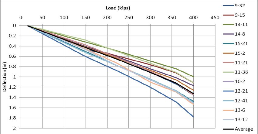
Figure 4 combines the results from the 13 performance tests that were
conducted along the east wall (Segments 9-15). This area has been selected for
detailed evaluation since the soil borings indicate rock elevation is highest closer to
the south wall and decreases moving north, while conversely embankment fill height
is greatest at the north and tapers to zero the closer to the south wall. Effectively, the
unbonded length and length of bond in Colma (as opposed to Franciscan) increase
from south to north.
Total deflection
Elastic deflection
Permanent deflection
Figure 4. East Wall Performance Test Data Summary
7Visual analysis of Figure 4 shows that test results exhibited a consistent form
of load deflection curve, but with total deflection ranging from 25 mm (1.0 in) to 46
mm (1.8 in) at test load. For further analysis, performance test summary data has
been plotted against the distance from the southern wall of the reservoir.
Figure 5. Pile Deflection vs. Distance from South wall of reservoir
Figure 5 compares the deflection (total, elastic, permanent) at 1780 KN (400
kips) for each performance test to the distance each pile is from the south wall of the
reservoir. Trend noted in this data are:
Total Deflection increases south to north
Relatively uniform elastic elongation of piles
Greater permanent set in piles at north end, particularly zone at +/- 500 ft
We note that although unbonded length increased at north end due to
thickness of embankment fill, the actual unbonded plus jacking length in testing
configurations was relatively uniform, ranging from 5.5 to 6.5 M (18 to 21 ft) for all
piles except the northern most two data points. This explains the uniformity of elastic
elongation amongst the performance test data sampled.
The trend of increase in permanent set moving northwards suggests that
more movement is required to mobilize friction in the dense Colma sand formation
compared to the Franciscan rock.
Figure 6 plots the creep performance per log cycle of time for piles at 1780 kN
(400 kips) relative to distance from reservoir south wall, with vertical axis set to 2 mm
(0.08 in) which is the maximum acceptance criteria. We do not note any clear trend
in magnitude of creep along this selected wall alignment, nor do any piles exhibit
high creep movements indicative of piles approaching geotechnical failure.
8Figure 6. Pile Creep at Test Load vs. Distance from South wall of reservoir
The load testing data demonstrates very good load transfer in both the Colma
and Franciscan formations, and piles did not approach failure in either bonding
strata. Due to the extremely stringent acceptance criteria of creep testing at full
seismic load, the Contractor selected a relatively conservative bond stress for pile
design and piles were not loaded to a level which demonstrated any significant
variance in load transfer between these two strata.
The acceptance criteria did not set a maximum deflection at test load, which is
slightly unusual, since the performance of a structure subject to seismic loading may
range between nominal damage and barely serviceable in response to pile
deflections ranging up to 50 mm (2 in). In general the load-deflection performance of
micropiles is of critical importance in the design of seismic systems and this topic is
discussed in further detail by Jameson, Panian & Rudolph (2008) and Jameson
(2009).
SUMMARY
The University Mound project is of specific interest due to its large magnitude,
challenging access and the requirement to test 100% of piles with anchor-type
acceptance criteria. The project was successfully completed, ahead of schedule and
on budget. Creative access solutions, combined with careful site management
enabled work in a safe and efficient environment. The stringent pile acceptance
criteria were controlled by creep testing at full seismic load and correspondingly, the
Contractor utilized relatively conservative load transfer values. All production piles
exhibited excellent load transfer in both the dense sand and weathered rock bonding
strata resulting in on-time and on-budget delivery for the project.
REFERENCES
Federal Highway Administration (FHWA) (1999) Geotechnical Engineering Circular
No. 4, Ground Anchors and Anchored Systems, Publication No. FHWA-IF-99-015.
Jameson, R., Panian, L., and Rudolph, B., (2008) Evolving Micropiles: Optimizing
Foundations for Seismic Retrofit, Proceedings of the 33rd Annual and 11th
International Conference on Deep Foundations, New York, NY, USA
Jameson, R., (2009) Micropiles for Seismic Retrofits, Deep Foundations Magazine,
Spring Edition.
9You can also read