Analysis of cracks in metro segment using FEM, rectification methods proposed and associated cost saving, points to ponder for young designers
←
→
Page content transcription
If your browser does not render page correctly, please read the page content below
POINT OF VIEW

          Analysis of cracks in metro segment using FEM,
        rectification methods proposed and associated cost
            saving, points to ponder for young designers
                                            Vivek Abhyankar and Raviteja Kilaparthi

One of the Elevated Metro Rail Viaduct projects near               further investigate this issue and to get a third party proof
Kolkata reported micro cracks in specific type of segments         checking certificate from one of the eminent institutes in
(S2 Type which had opening in a deck), repeatedly. The             India (i.e. IIT) the authors performed detail 2D analysis
problem persisted for more than one year or so due to              and then 3D finite element analysis. The analysis was
lenient approach from the owner, consultant and the                done using a good software. Figure 1 shows model of
contractor. But after some time when the supervision               S2 segment with the stress contours. Various techniques
agency noticed it, they almost stopped the work with an            were adopted so as to simulate the real behaviour in the
explanation as “poor workmanship by the contractor”.               computer model. Later, the analysis was cross checked
Then the construction team referred this problem to the            by other software programs and similar conclusions were
authors of present paper. Authors tried to investigate             derived. To complete the whole modelling, analysis,
the matter in detail including QAQC programs, designs,             design and verification it took some time, during which
safety precautions etc. and came up with a possible cause          many innovative thoughts and techniques were tried /
of cracks as ‘deficient reinforcement detailing around the         adopted by the authors, which helped to establish the
opening in the deck slab’ and not the workmanship. To

Figure 1. Showing a model of S2-segment with the stress contours

                                                                                           The Indian Concrete Journal March 2018   63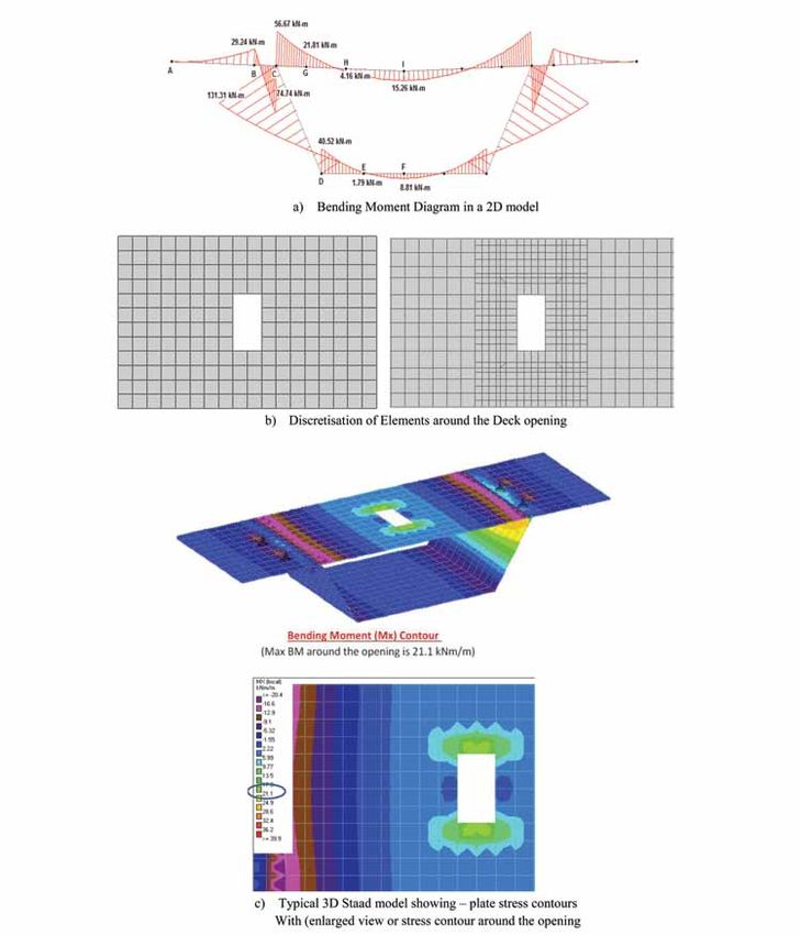
POINT OF VIEW

           (a) Local Thickening around the Opening in S2 segment and a typical photo of a crack developed on edge
           of a segment

           (b) Actual Cracks in S2 segment (left image shows crack other than diagonal and right image crack penetrating
           towards the thickness of concrete after extending till edge)

             (c) Schematic paper model with an opening before and after application of a force is shown above. In the second
             image i.e. after application of force the cracks developed in diagonal direction can be clearly seen

     Figure 2. Model and photos to demonstrate the effect of opening and associated diagonal cracks

64     The Indian Concrete Journal March 2018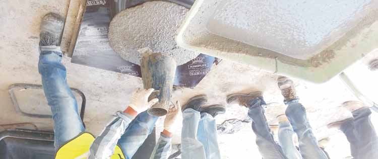
POINT OF VIEW
fact and finally to get the approval from the eminent            / specified lifting points approved by the designer; during
authorities/ third party proof checkers.                         lifting of a segment, complete weight of the Segment is borne
                                                                 by lifting points. If the lifting-span (i.e. distance between
In the present paper the authors have explained this             lifting points) is not maintained as per the design, then
process and the learning they had from this complete             additional stresses may generate in each component of the
exercise and the financial implication (benefits) in             segment (like Top deck, web and soffit etc.) and may even
general, purely from academic point of view. This paper          increase beyond the permissible values (fcr=0.7√fck), resulting
will be very much useful for budding engineers / bridge          into formation of cracks. In some cases viz. for the segment
designers while detailing the reinforcement in segmental         with opening in deck or soffit (where the opening is kept
construction.                                                    for maintenance purpose, ref Figure 2) if the detailing goes
                                                                 wrong, especially for the reinforcement around the opening,
INTRODUCTION                                                     the cracks will develop diagonally and may propagate
                                                                 outwards and in adverse cases even extend throughout the
Bridge construction has several types; the two broad
                                                                 complete thickness of concrete section. Similar detailing
categories of bridge construction are (i) precast construction
                                                                 mistake had happened during the detailing of the segment
and (ii) cast in-situ construction. In precast construction,
                                                                 reinforcement in one of the Elevated-Metro viaduct design
the segments are manufactured in ‘casting yard’, cured
                                                                 projects near Kolkata. In this paper the complete incidence
till gain of sufficient strength in ‘stacking yard’ and then
                                                                 and learning are shared purely from academic point of view
sequentially all segments are transported to construction
                                                                 without mentioning the names of parties involved. Hope the
site and launched, one by one, using various bridge
                                                                 reader of this paper will learn about the intricacies involved
launching techniques. Then segments are glued together
                                                                 in the detailing of reinforcement and will find it useful in
followed by application of temporary stress to squeeze-out
                                                                 their day-to-day designs.
the entrapped air at joints between two segments, the post-
tensioing is done to form one integral span. Whereas, in cast
                                                                 In this elevated metro viaduct project, the same type of
in-situ construction method, the whole structure is cast at
                                                                 cracks was seen around the openings. These cracks were
the construction site itself, using formwork and supporting
                                                                 transmitting outwards in diagonal direction, during lifting.
staging arrangement. In precast segmental construction,
                                                                 Usually in any segment with opening, the periphery of the
while shifting the segments from casting yard to stacking
                                                                 opening is thickened / stiffened using RCC peripheral beam
yard and there onward to site, they are lifted at predecided

Figure 3. Description of clause 9.6.1 from SP 34:1987

                                                                                          The Indian Concrete Journal March 2018   65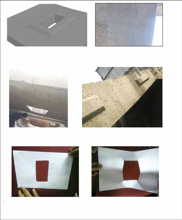
POINT OF VIEW
     or a steel framing so that the stiffness is maintained properly   segment, which could not be obtained as per the contractual
     (ref. Figure 2a). Figure 4 show typical cross section and plan    agreements of the said project. Hence authors had to perform
     of segment ‘S2’ with the key dimensions.                          fresh calculations to verify the phenomenon of cracking.

     IDENTIFICATION OF THE PROBLEM AND                                 At the beginning authors tried to make a 2D analysis of
     PLANNED ACTIONS                                                   segment to determine the forces (bending moment, shear
                                                                       force and axial force) in various parts. After obtaining these
     After the work was ceased on account of persistent cracks
                                                                       forces still the cracks in the segments could not be justified;
     the authors inspected all the relevant Quality control record
                                                                       hence a detail 3D FEM analysis had to be carried out. After
     (viz. material testing reports, procedures etc.) and all were
                                                                       processing the 3D model some clues were obtained. Further
     found in order; even all were approved time to time by the
                                                                       the 3D model was refined towards accuracy (Figure 7
     client’s representative and the DDC. Hence there was hardly
                                                                       showing the schematic analysis models and Figure 8
     any scope for deviation from the desired quality of concrete /
                                                                       showing the forces in 2D and 3D models).
     reinforcement and workmanship. Hence the authors focused
     their attention over the design / drawing and detailing. In
     design there were two broad areas – (i) the design of main        GEOMETRY OF THE SEGMENT AND
     structure and (ii) design of temporary works and its effect       REINFORCEMENT DETAILS
     on the permanent work. At beginning itself it was noticed         The geometry of the typical S2 segment can be seen from
     that the DDC had released two revisions of drawings for           the figure (cross-section, plan and elevation). M-40 grade of
     the segments under discussion. The first revision was ‘A’         concrete using OPC (No fly ash/micro silica/GGBS etc. was
     showing the orientation of opening ‘transverse to the bridge      used) and Fe-500 grade reinforcement was used for casting
     axis’ and then the second revision ‘B’ was issued after           segments. Modulus of elasticity of concrete Ec of 5000√fck
     about six months gap where the orientation was changed            (in MPa) and that of steel reinforcement as 2.0 x 10⁵ MPa
     in ‘longitudinal to the bridge axis’. As revision ‘B’ was a       was considered by the original designer as per the Design
     last (latest) approved version, the complete construction         Basis Note (DBN). Along the opening 2-T.16mm bars were
     took place as per revision ‘B’ of the drawing. But the            provided at top at bottom (i.e. 4 bars total) along all four
     reinforcement detailing in revision ‘B’ was kept same as          edges and diagonal bars of 2-T.10mm were provided at top
     revision ‘A’ by the Jr. Designer (by mistake)! Figure 5 shows     and bottom, as shown in Figure 5c. Poisson’s ration of 0.25
     the orientation of the opening and reduction in the concrete      was specified in design but was not used in original design.
     area, Figure 5 also shows reinforcement details around the        Even in original design detail temperature, shrinkage, creep
     opening as per revision ‘A’ and ‘B’. Figure 6a shows the          analysis was done. It was found that the temperature was
     segment in lifted position with lifter beam and segment           not cause of the cracks but it was purely structural.
     stacking position (ref. Figure 6c). After the revision ‘B’ was
     compared with standard detailing practices prescribed by          In SP-34 code the types of openings in concrete are classified
     SP 34 : 1987 version of code (clause number 9.6.1), the lacuna    as (i) small opening and (ii) big opening for which the
     in the reinforcement detailing came to the notice. The said       reinforcement detailing deffres; unfortunately the code has
     clause (i.e. 9.6.1) is reproduced as below, for completeness      not mentioned a specific criteria to distinguish between
     of explanation.                                                   these two; hence often the difference of opinion arises
                                                                       between designer and the proof checker. Hence in important
     The reinforcement provided in the S2 segment around               cases the designer should himself ascertain the stresses
     the opening was 50% of the required, as per the above             around the opening, and atleast adhere to the minimum
     mentioned clause. The designer himself claimed that for the       reinforcement (if not detail analysis is done). In the present
     forces considered, there was no requirement of providing          project the reinforcement provided along the opening was
     additional 50% reinforcement and SP34 code need not to            far lesser that the minimum prescribed reinforcement for
     be followed. In the same way, the diagonal reinforcement          even the small opening. In addition, due to the revision in
     provided were 39% of the required reinforcement as per said       the drawing issued at last moment there was further mistake
     clause. Even the development length for diagonal bars was         (shortfall) in the reinforcement.
     lesser than that specified in SP-34.
                                                                       COMPUTER SIMULATION (MODELING)
     For further investigations the authors requested the designer
                                                                       Finite element analysis (FEA also called FE method or simply
     to share the complete design calculations of the said
                                                                       FEM) is a computerized method of structural analysis in

66     The Indian Concrete Journal March 2018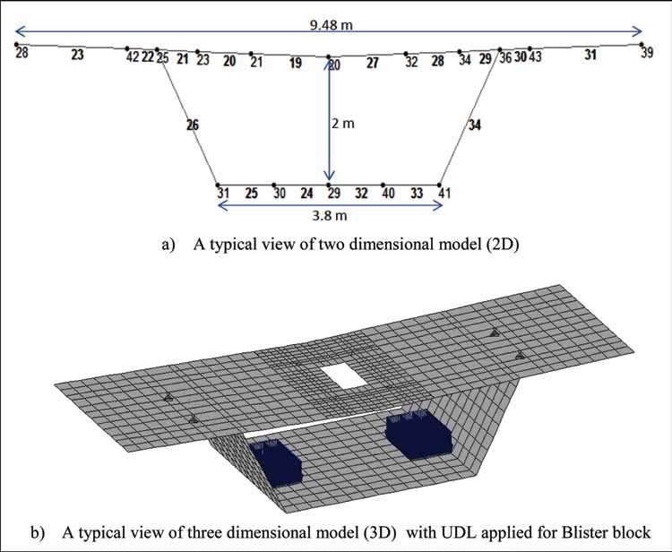
POINT OF VIEW

Figure 4. Section showing geometry of the segment along with key dimensions

                                                                              The Indian Concrete Journal March 2018   67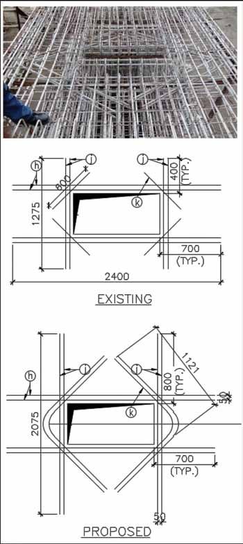
POINT OF VIEW

     Figure 5. Reinforcement detailing around the opening in revision ‘A’ and revision ‘B’

68     The Indian Concrete Journal March 2018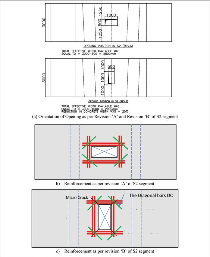
POINT OF VIEW
which a main structure is sub-divided into smaller elements;               software may be used. But as in present case the loads were
this process is called as ‘discretisation’. The assemblage of              well within the elastic limits and present software could
all the elements together is called as mesh, and it is nothing             give the results as per real behavior, such need of advance
but a mathematical model resembling the shape of main                      software did not arise.
structure / object. FEA finds out required stresses and
displacements developed at each element (nodes) in a mesh                  Two conditions, namely (i) segment lifting and (ii) segment
(Locally and globally) due to the applied forces. As on today,             stacking were idealized in the segments by changing the
there are many professional software programs available for                support conditions. In stacking of the segments usually the
FEM modelling and analysis. In present study, a full scale                 segments are stacked in two layers (ref. Figure 6b) but in
3D model was developed in a good software to analyze                       rare cases the segments are stacked in three layers. Figure 6c
the behavior of cracks developed around the opening of a                   illustrates the three layers stacking in some other project. In
typical box girder segment, namely ‘S2 segment’ (second                    present project, considering the position of S2, there were
segment in a bridge viaduct of said work) during its                       further two possibilities, (i) S2 in bottom layer (ii) S2 in top
lifting. In the model only concrete could be modeled and                   layer. As segment S2 were the heaviest segments among all,
not the reinforcements (especially reinforcements around                   they had to be stacked in the lower layer and even the design
the opening); for modeling the reinforcements advanced                     consultant checked and confirmed the adequacy to withstand

Figure 6. Showing segment in lifting position and stacking position (respectively)

                                                                                                    The Indian Concrete Journal March 2018    69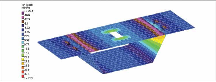
POINT OF VIEW
     load from the upper segment. Usually the construction sites      tried (Figure 7). After the stress contours were obtained
     prefer three layer stacking as it makes more stacking place      around the opening, it was realized that the stresses are
     available. But in such case the safe bearing capacity of soil    varying along the element corners and are extremely high.
     should be higher. In Kolkata as SBC is generally low (due
                                                                      As the element size was larger (500mm x 500mm) the finer
     to clayey soils) in present project 2 layer stacking was used,
                                                                      behavior could not be obtained and the authors decided to
     which fortunately reduces the load on S2 segment. But still
     the segment cracks due to inherent reinforcement detailing       refine the mesh size around the opening; thus the elements
     mistakes.                                                        were reduced to 125mm x 125mm (rectangular and triangular
                                                                      elements, Figure 8b shows the refined elements pattern).
     As mentioned earlier the construction took place as per
     revision ‘B’ of the drawings, the modeling was done as           ANALYSIS RESULTS AND CORRECTIVE
     per position in revision ‘B’. The plate stress contours were
                                                                      ACTIONS
     obtained for both positions (lifting and stacking). The
     plate stress contours are shown ahead in this paper. As an       The various results obtained from 2D and 3D analysis are as
     alternative to FEM model a 2-Dimensional model was also          presented in the figure.

     Figure 7. Schematic models of the segment

70     The Indian Concrete Journal March 2018
POINT OF VIEW
Figure 8. Forces in various components
The Indian Concrete Journal March 2018 71POINT OF VIEW
Bending moments in various elements around the opening, in
orthogonal (X, Y) and oblique / skew directions were found
out from the analysis and result of the model. The working
stresses developed due to the resulting bending moment
were found out and compared with the permissible tensile
stress values as per IS: 456 clause number 6.2.2 (fcr=0.7√fck).
RCC design by working stress method was carried out to
estimate the required stresses. Two such designs were
carried out (i) for present project and (ii) another for a similar
project with same loading and other conditions, which
was already executed successfully. The stresses in ‘i’ were
higher than that in ‘ii’ and also that as per the clause 6.2.2 of
IS:456. The reinforcement detail in case ‘ii’ was found to be
in order with the recommendations of BIS-SP-34 code. These
findings were recommended to third party proof checking
agency (IIT), and got readily approved.
After the outcome this study was brought to the notice of
the client & consultant. They asked to perform the segment
lifting at 7th than the 3rd day. As per contract specifications
the segments were to be lifted at 3rd days or gain of strength
to concrete whichever is later. Even the lifting is done at 7th
day, still the segment cracked. Then a few segments were
lifted at 14th & 28th day. Even these segments cracked. Now
the client & consultant got convinced with the shortfall in
the reinforcement & not the shortfall in concrete strength.
But this all consumed some project duration.
RECTIFICATION MEASURES AND COST IMPACT
After identification of the root cause of cracks, another
question was how to rectify these cracks in (i) already
erected segments and (ii) in segments to be cast in future.
The segments to be cast in future were provided with
the additional reinforcement as shown in Figure 9 as per
SP-34 recommendations and it was noticed that there were
no cracks i.e. the issue of cracking was resolved. For the
old segments IIT recommended the treatment using epoxy
grout.
The cost of typical S2 segment was ranging between 3.5 lakh
and 4.0 lakh in this project. When the PMC rejected about
13 segments on gross basis (without any in depth root cause
analysis), the contractor got panic because it would have
Figure 9. Corrected reinforcement detail around the opening cost them penalty of 48 lakh (approximately); not only so,
72 The Indian Concrete Journal March 2018POINT OF VIEW
the repair of already launched segments would have cost 6.2.2 and also as per the reinforcement detailing in SP34
them penalty of another 55 lakh (Thus the total penalty of code. Thereby it was noticed that the stresses around the
about one cr. rupees along with time loss & bad name in the opening of S2 segment of the said project were beyond
industry). the permissible values, which was the main cause for the
development of cracks around the opening. The working
After the author of paper scientifically proved that the stresses for the S2 segment of similar successfully executed
mistake was not with the workmanship but the reinforcement project were less than the permissible values as per the
detailing, the consultant and the client, both got worried. said codes. So, the authors of the paper has proved that the
They got their design reviewed from many experts in the reinforcement detailing had gone wrong for the S2 segment
industry and finally understood that there was a lacunae in of present ongoing project and it was not as per the norms of
their own designs and drawings. Also the instruction used SP34 code but not the workmanship problem. The same was
by the client to lift the segment at 14th day was against their approved by eminent proof checking agency.
own contract specification and would have resulted into
serious time loss i.e. from 2yr contract duration to about 8yr The proposed exercise made the authors to explore all
along with additional cost resources, eventually the contract possibilities by which the segments could crack and cross
rates (due to escalation) would have become unjustifiable check the attributing causes at site. Correct detailing of
for them. So finally client has withdrawn this instruction. the reinforcement at the original design stage would have
Later, client and consultant requested contractor to suggest avoided complete delay and even wastage of construction
the rectification measures. On this, contractor submitted the materials used for rectifications. This case study is a classic
proposal of ‘additional reinforcement’, which was costing example to the budding designers as (i) computer software
merely 2 lakh rupees in remaining segments of whole is merely a tool, inferior / insufficient input could cause
project. Whereas the segments which were pre-erected were inferior results (GIGO) as in present case; (ii) while reducing
retrofitted with epoxy grout; the proof checker had already the reinforcement below the minimum recommended
certified that as the cracks appeared in S2 segments during standards of IS / IRC codes (which are based of some
lifting were in transverse direction, they did not influence research / reference) or a deviation alike, one has to carry out
the structural performance of the bridge after application out in depth study / investigations to avoid the adversities
of Post-Tensioning force and mere epoxy grouting was caused in present case. Each project is unique; designers /
sufficient. Thus the estimate of 1cr rupees reduced to just a contractors / PMC and client all shall be alert at all stages
few lakhs. Client, consultant, contractor and even authors (design, detailing, casting, erections), without any prejudice.
learnt many lessons from the final technical and financial Site engineers should not hide the facts observed at site till
output of this whole mission. Thus whole assignment was the end they become really sore. The present paper is really
concluded technically & happily. an eye opener for all bridge designers & contractors and
should be followed with open eyes.
SUMMARY AND CONCLUSIONS
The problem was identified from the construction site After the present study was concluded, the authors came
sources. Authors obtained the available drawings (GAD across similar case of cracking around opening segment at
and Reinforcement) of S2 segment namely Rev-A, Rev-B another road project in Delhi. Such repeated occurrence of
and drawings from similar viaduct project. 2D and 3D FEM cracks due to reinforcement detailing mistakes inspired the
modeling of S2 segment was done in the software with authors to compile present paper to avoid repeated detailing
supports as lifting points and loads as self weight of S2 error among young bridge engineers.
segment and UDL for Blister block. For the accurate results,
the elements around the opening were refined. From both the References
models, the required bending moments especially bending 1. ______ Plain and Reinforced Concrete, IS 456 : 2000, Bureau of
moments for the plate elements around the opening were Indian Standards, New Delhi.
obtained. Further working stresses were calculated with
2. Handbook on Concrete Reinforcement and Detailing,
respect to the obtained bending moments and compared
SP-34 :1987.
with the permissible stress values as per IS 456 2000 clause
The Indian Concrete Journal March 2018 73POINT OF VIEW
Er. Vivek Abhyankar, C.Eng (India), formerly working at Afcons Infrastructure Ltd., has 18+yrs of
industrial experience in planning and design, detailing, construction of various enabling and permanent
works in reinforced concrete and steel. He is a life member of various Institutes, professional trainer,
visiting faculty for graduate and post-graduate students in structural engineering, guide for AMEI projects
in civil engineering. He is a Gold medal winner in structural engineering, wrote various technical papers,
contributed to two books, guide to various technical thesis, technical trainer and a certified internal auditor.
Er. Raviteja Kilaparthi holds an M.Tech in structural engineering from VNIT-Nagpur. He is presently
working as a design engineer in eminent firm in Mumbai. He has presented two technical papers in
renowned journals / workshop. He has experience in the design and conceptualization of various enabling
works required in bridge construction field.
74 The Indian Concrete Journal March 2018You can also read