Takeoff Performance Analysis of a Light Amphibious Airplane
←
→
Page content transcription
If your browser does not render page correctly, please read the page content below

IOP Conference Series: Materials Science and Engineering

PAPER • OPEN ACCESS

Takeoff Performance Analysis of a Light Amphibious Airplane
To cite this article: Sinchai Chinvorarat et al 2021 IOP Conf. Ser.: Mater. Sci. Eng. 1137 012010

View the article online for updates and enhancements.

 This content was downloaded from IP address 46.4.80.155 on 20/08/2021 at 01:46
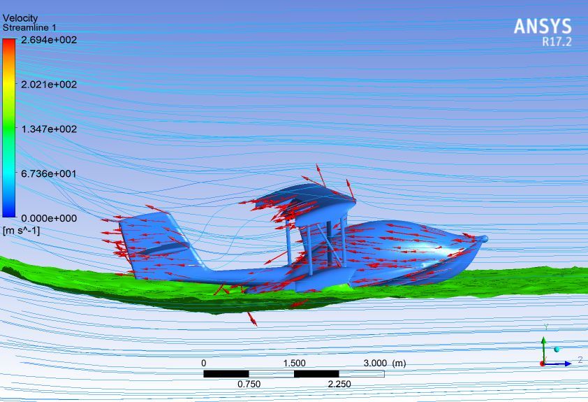
The11th International Conference on Mechanical Engineering (TSME-ICOME 2020) IOP Publishing
IOP Conf. Series: Materials Science and Engineering 1137 (2021) 012010 doi:10.1088/1757-899X/1137/1/012010

 Takeoff Performance Analysis of a Light Amphibious Airplane

 Sinchai Chinvorarat1,*, Boonchai Watjatrakul1, Pongsak Nimdum1,
 Teerawat Sangpet1, and Pumyos Vallikul1
 1
 Department of Mechanical and Aerospace Engineering
 King Mongkut’s University of Technology North Bangkok
 1518 Pracharaj 1, Bangkok, 10800, Thailand

 *Corresponding author: sinchai.c@eng.kmutnb.ac.th

 Abstract
 The performance analysis of a light amphibious airplane during takeoff from the water
 surface has been presented in this paper. The airplane is one of the light amphibious
 airplane series built in Thailand with a bi-wing configuration. The conceptual design
 aims to build a short takeoff and landing (STOL) amphibious airplane. The
 mathematical model cooperated with several complicated parameters is presented and
 solved by MATLAB. The water-drag resistance of the airplane is estimated from
 typical seaplane hull NASA technical information, which enhances the correctness of
 the model at takeoff configuration. The simulation reveals that the seaplane can
 successfully takeoff from calm water in 24.5 seconds at the speed of 54 KCAS and an
 approximate distance of 890 feet with the AOA of 10 degrees.
 Keywords: takeoff performance analysis, water-drag resistance, light amphibious
 airplane

1. Introduction
The "NAX" project initiated by the Royal Thai Navy research team has been started since the year 2002,
aiming to design and build a light, versatile amphibious airplane (seaplane) and exploiting several
missions such as coastal patrol, search and rescue, fire extinguish including any others mission assigned
by military and civilian purposes. The initial version of the airplane, NAX-3, has been designed from
the concept of the EDRA Aeronautic Super Pétrel, an amphibious pusher configuration biplane. The
NAX-3 has demonstrated its satisfaction flying qualities in both performance and safety, but the total
weight of the airplane is above 650 kilograms, which is the number classified as a light sport airplane
category stated by the Civil Aviation Authorities of Thailand (CAAT).
 The new design of the NAX-4 project has started with the concept of modifying an amphibian
pusher bi-wing configuration. The main seaplane structure is mostly made from composite, gains
benefits in lightweight control, and enhances the strength of structure with aluminum alloy as a
structural bone. By the retractable landing gears, the seaplane can takeoff and landing on a short airfield
or water runway. A more powerful 115 Hp, Rotax 914 piston engine with three blades constant pitch
propeller is installed as a "pusher" bi-wing configuration. The seaplane basic design performance is
shown in Table 1.

 Content from this work may be used under the terms of the Creative Commons Attribution 3.0 licence. Any further distribution
 of this work must maintain attribution to the author(s) and the title of the work, journal citation and DOI.
Published under licence by IOP Publishing Ltd 1
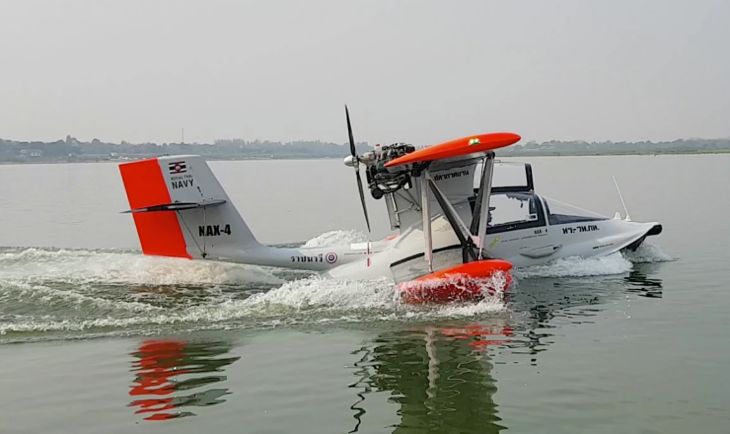
The11th International Conference on Mechanical Engineering (TSME-ICOME 2020) IOP Publishing
 IOP Conf. Series: Materials Science and Engineering 1137 (2021) 012010 doi:10.1088/1757-899X/1137/1/012010

 Table 1. “NAX-4 light amphibious airplane
 Specifications:
 Crew 1 person
 Capacity 1 person
 Length 19.88 ft
 Upper Wingspan 32.94 ft
 Upper Wing area 97.52 ft^2
 Lower Wingspan 18.77 ft
 Lower Wing area 52.96 ft^2
 Cabin width 4.12 ft
1 × Rotax 914 ULS piston, 115 hp Empty weight 880 lbs
 Max fuel capacity 40 gallon
 Max takeoff weight 1,430 lbs
 Performance:
 Maximum speed 179.81 mph
 Cruise speed 141.47 mph
 Stall speed 53.98 mph
 Endurance 5 Hrs
 Rate of Climb 863.75 fpm
 Take off Distance (Runway) 650 ft
 Take off Distance (Water) 890 ft
 Landing Distance (Runway) 600 ft
 Landing Distance (Water) 700 ft

 Figure 1. “NAX-4 amphibious light airplane” general dimension.

 Since the seaplane can operate from the water surface, it's motion is distinguished from
 conventional land airplane [1], [2]. When the seaplane left the water surface, it operates like other fixed-
 wing airplanes but draggier than a landplane due to its hull design and many numbers on posts that
 support wings and undercarriage [3], [4]. The determination of the airborne performance follows the
 procedure typically determine the airborne of the landplane. The motions of seaplanes on the water,
 however, introduce additional complications. The seaplane goes through a transition process from a
 state of static buoyancy to dynamic planning [5]. The seaplane must be designed to smoothly
 transferable in four phases, i.e., displacement phase, hump or ploughing phase, planning or on the step
 phase, and airborne or liftoff flight.

 2
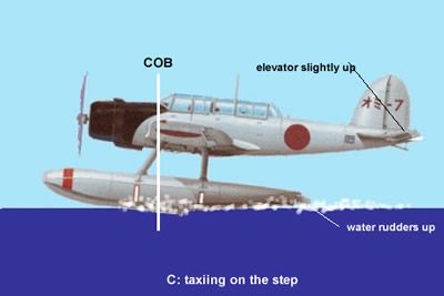
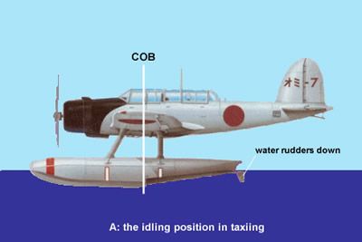
The11th International Conference on Mechanical Engineering (TSME-ICOME 2020) IOP Publishing
IOP Conf. Series: Materials Science and Engineering 1137 (2021) 012010 doi:10.1088/1757-899X/1137/1/012010

 This paper determines the analysis of the NAX-4 amphibious light airplane in takeoff
configuration incorporate with essential and imperative parameters that help to understand the
characteristics of the seaplane in detail. The results from the modeling analysis will be validated and
verified through the actual flight test.

 Abbreviations
 " Buoyancy force
 &'
 ∆ = , Buoyancy force coefficient
 () *+
 -
 - = Speed coefficient
 *+
 . Resistance coefficient
 0123 Trim angle
 Water resistance
 &16789 Froude water resistance
 Linear velocity of the airplane
 Incidence angle
 0123 Trim angle
 Mass
 Thrust
 Gravity

2. Seaplane Motions in the Water
When the seaplane is taxying with an idle RPM engine, it is considered as a displacement phase [6].
Normally the taxi speed is about 6-8 knots so that the propeller will not pick up water spray that causes
serious erosion problems of the propeller blade. Since the seaplane has no brakes, it is very important
to taxying at low speed to avoid any collision in a confined area. When the power is increased
significantly above idling, the seaplane will usually become nose-up or ploughing position. For
seaplanes that have a high thrust-line will tend to nose down upon applying power, it is imperative that
the elevator should be in the full up position. The ploughing position is about the combination of high
velocity streamline flows through the elevator and the hydrodynamic force exerts on the immersed part
of the hull. However, hydrodynamic or water drag becomes the major part of the force resisting
acceleration. This resistance reached its maximum at a speed of about 30 knots, just before the hull is
placed into the planing phase. The trim angle needs to be slowly increasing approximately two more
degrees helping the hull to ride on the step. The point of the highest resistance is called the "hump."
After the hump is passed and the seaplane is traveling on the step, and water resistance R continue to
decrease.
 The planning or step position is attained by advancing the throttle to full power, and the
elevator is slightly up. As the seaplane accelerates, it will gradually assume a nose-high pitch attitude
raising the hull up to the step area. As a result of aerodynamic and hydrodynamic lifting, the seaplane
is raised high in the water, allowing the hull to ride on top of the water wave. The airborne is merely
transferring lift force from the hull to the wing by applying back elevator pressure resulting in the
seaplane lifting off the water and becoming airborne. To avoid a rhythmic pitching motion caused by
dynamic instability in forces along the hull, so-called "porpoising" while on the step, it is crucial to
maintain the proper pitch angles during the takeoff run. Too much back-elevator pressure during
planning will force the aft part of the hull more profound into the water, creating a strong resistance and
retarding takeoff. On the contrary, insufficient bake elevator pressure will cause the hull to remain in
the water, which results in excessive water drag. During the seaplane acceleration, the water is
increasing sprayed upward, outward, and rearward from the bow and will be directed into the propeller,
causing erosion of the blades as well.

 3
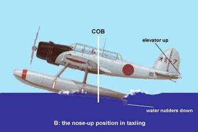
The11th International Conference on Mechanical Engineering (TSME-ICOME 2020) IOP Publishing
IOP Conf. Series: Materials Science and Engineering 1137 (2021) 012010 doi:10.1088/1757-899X/1137/1/012010

 Figure 2. displacement phase, hump or ploughing phase, planing or on the step phase.

2.1 The Hydrodynamic Force, Resistance, and Drag Force
For the seaplane operating near the water surface, the hydrodynamic force is affected by gravity acting
on the wave and by surface tension [7]. By dimensionless analysis, the force acting for the seaplane
body can be expressed by:
 @ (-F - (- J F
 > = C A A (1)
 A G *F K
where k is a constant coefficient, ρN is water density, is the seaplane velocity, and is the submerged
length of the seaplane in the water. Equation (1) illustrates that the hydrodynamic force depends on the
function of three characteristic dimensionless ratios, the Reynolds Number, the Froude Number, and
the Weber Number lied in order. The Reynolds Number indicates the ratio of dynamic forces to viscous
forces, the Froude Number is the ratio of dynamic forces to gravity force, and the Weber Number is the
ratio of dynamic forces to surface tension forces. In the model of the seaplane framework, the effects
of Webber number are confined to low speeds and are considered constant, which equals to unity.
 The total resistance of a seaplane consists of (i) hull form water drag, which includes wave
and eddy drag, (ii) parasitic drag, and (iii) induced drag. The hull drag portion of the hydrodynamic
force while the seaplane is moving on the water surface can be determined from the resistance
coefficient . as:
 .
 . = , (2)
 () *+
where is water resistance, and B is the seaplane cabin width.
The parasitic drag and induced drag can also be determined through a drag coefficient P using a
quadratic polynomial as:
 SJ
 P = P32Q + T (3)
 U.W..9
where P32Q is the minimum drag coefficient, AR is the reference aspect ratio, and e is Oswald
efficiency.
These resistances directly affect the takeoff safety and performance of the seaplane and yet are taking
into account in the design and production phase.

3. Seaplane Takeoff Estimation
The seaplane takeoff from the water surface is more complicated than conventional airplanes due to the
complexity of water resistance and aerodynamic drag. The seaplanes are generally very draggy due to
their shape of the hull and associated support structure, generating lots of drag. However, the shape of
the seaplane is dictated by hydrodynamic design and operation, and yet it is practically impossible to
reduce its drag. Drag can be minimized by other means such as using aerodynamic strut profile, keep
landing gear behind a smooth door compartment, or making fuselage and main parts of the seaplane by
composite material (to reduce weights and number of rivets), etc.
To be able to lift off from the water surface safely and efficiently, several parameters have to be
considered as follow,
Buoyancy force coefficient:
 &' ∆
 ∆ = , = , (4)
 () *+ () *+
where, " = C ∀= ∆ is the Buoyancy force.
the maximum Buoyancy force coefficient (when the seaplane is stationary) is denoted as:
 C
 ∆\ = , (5)
 () *+
and speed coefficient as a function of the seaplane speed is denoted by:

 4
The11th International Conference on Mechanical Engineering (TSME-ICOME 2020) IOP Publishing
IOP Conf. Series: Materials Science and Engineering 1137 (2021) 012010 doi:10.1088/1757-899X/1137/1/012010

 -
 - = (6)
 *+
To estimate the water-resistance of the seaplane more effectively, the water resistance coefficient . as
a function of speed coefficient - can be obtained from the experimental model towed in the water tank
[8]. However, NACA TN-2481 [5] provides the graph of . and - for planing-tail seaplane model
and can be the empirical curve fitting of a Gaussian function as:
 cd ef.g\h J cd ef.,mh J cd eJ,.mf J
 b b b
 . = 0.05789 \.hijf + 0.0273 \.Ji,j − 0.3322 ff.hm +
 cd e,.JJh J
 b
0.07924 f.gif (7)

For reduction of water resistance with loading, the following expression is given:
 S
 .∆ = . . ( ∆ ) (8)
 S ∆\
and water resistance is given by:
 = .∆ C s (9)
Also, the trim angle curve can be approximated by the equation:
 tJ btf
 0123 = @ + ∗ 1 + ℎ - + (10)
 A
 |.A}~
where = = −(2.647 + -@ )
 SdJ bSdf

 Figure 3. Trim angle and water-resistance as a function of speed coefficient.

From Figure 3, the “hump” or the peak of . , the value indicates the maximum water resistance
resulting from the seaplane reaches its hull speed [9]. Practically, it means the seaplane is on the step
and ready for the pilot to rotate the seaplane. The trim angle indicates the orientation of the seaplane on
the water surface during takeoff. It is very important for takeoff analysis because it directly affects the
angle of attack (AOA) of the seaplane. By adding the trim angle to the AOA, the seaplane will merely
on the step at a certain - value at the planing stage and ready to airborne [10, 11].

The friction resistance of submerged surfaces, while the hull is in the planning stage, by William
Froude is introduced by:
 &16789 = . C . Q (11)
where is the coefficient of friction resistance depends on the hull surface, C is the wetted area, is
constant depend on surface quality, usually close to 2.
The thrust of the seaplane as the functions of power and velocity for fixed-pitch propeller can be
approximated by a cubic spline method as the form [12, 13]:

 = s + A + + (12)
when , , , are constants and can be determined from the following matrix equation

 5
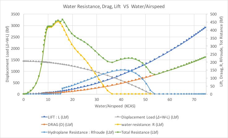
The11th International Conference on Mechanical Engineering (TSME-ICOME 2020) IOP Publishing
IOP Conf. Series: Materials Science and Engineering 1137 (2021) 012010 doi:10.1088/1757-899X/1137/1/012010

 0 0 0 1 …0†02‡
 s A
 S S S 1 S
 =
 3 SA 2 S 1 0 − ˆ . +>ˆ / SA
 >s
 > > 1
 A >
where ˆ is the propeller coefficient, > is maximum level airspeed, S is cruise airspeed, …0†02‡ is
static thrust at zero airspeeds, +>ˆ is engine brake horsepower, > is thrust at maximum airspeed, S
is thrust at cruise airspeed.

 Figure 4. Thrust-velocity for fixed-pitch propeller.

Equation of motion for 2-D [14] taking off from water of seaplane in the longitudinal axis is
expressed as:

 . − − − &1678 = (13)

where is ramp up the factor of a pilot to slowly increase power from takeoff, which is given by the
expression:

 0.1 + 0.9 10 < 10
 =
 1 ≥ 10

4. Simulation Results
The necessary information of the NAX-4 light amphibious airplane [15, 16] for 2-D takeoff
estimation under the calm water condition is given in Table 2.

 Table 2. Technical information of NAX-4.
 Fuselage Beam B 4.27 ft
 Fuselage Water Length L 13.55 ft
 Wing Span b 32.94 ft
 Wing Area S 152.85 ft^2
 Wing Aspect Ratio AR 7.1
 Wing AOI wrt Keel iw 4 degrees
 Gross Weight W 1430 Lbf
 Rotax 914 UL Engine Power P 115 BHP
 Propeller Diameter Dp 6 ft
 Spinner Frontal Area Aspinner 5 ft^2
 Maximum Speed @5000 ft Vmax 151 KCAS
 Propeller Efficiency h 0.82
 Thrust Function @ Max Power T 1972.32 Lbf

 The simulation shows that the seaplane starts increasing power gradually from idle to full power
in 10 seconds. The seaplane starts to pick up the speed, and also the aerodynamic drag, water drag, and
lift force start increasing at different rates. However, the water resistance that is the function of the
speed starts growing exponentially and reach the top at hull speed in 12 seconds, making the seaplane
to be the planning stage and begin to get on the step at this period. Once the seaplane is on the step, the
hydrodynamic resistance, •‘’“”• , starts its value due to the submerged part of the hull while the water
 6
The11th International Conference on Mechanical Engineering (TSME-ICOME 2020) IOP Publishing
IOP Conf. Series: Materials Science and Engineering 1137 (2021) 012010 doi:10.1088/1757-899X/1137/1/012010

resistance reduces to “zero” at the speed of 36 KCAS. The pilot can rotate the seaplane at this speed but
must be aware of the rear shifting of the center of buoyancy (CB) that could make the seaplane enters
porpoising if too much rotation. The seaplane will lift off the water when the displacement load becomes
“zero” at the speed of 54 KCAS within 24.5 seconds, and the total distance is 893 feet.

 Figure 5. Lift, Drag, Water resistance, Hydroplane resistance, Displacement Load versus
 Water/Airspeed.

 Figure 6. Displacement Load, Thrust, Total Resistance versus Time.

 The takeoff configuration of the seaplane has been analyzed using ANSYS- fluent in VOF
module. The 3-D model of NAX-4 is built without engine and propeller to study the seaplane behavior
at the planning stage. The FEM mesh is tetrahedrons with 538,282 elements and 104,052 nodes. The
multiphase – VOF CDF model is analytically selected along with a realizable k-epsilon model. The
couple solution technique is chosen with a flow courant number equal to 0.5, and the surface tension
between two media, air and water, is set to be 0.75. The AOA of the seaplane is 10 degrees, and the
airspeed is 30 meters/sec.
 The simulation shows that the lift coefficient F converges to the value of 1.007 while the drag
coefficient P converges to 0.08, making the aerodynamic lift equal to 1,515 lbf at liftoff. One can
visualize some turbulence after the upper wing that creates drag to the seaplane and the surface shear
(red arrows) along the body surface. This turbulence affects the stabilizer fins and elevator for
maintaining the trim angle, which the pilot needs to be aware of while lifting off the seaplane.

 7
The11th International Conference on Mechanical Engineering (TSME-ICOME 2020) IOP Publishing
IOP Conf. Series: Materials Science and Engineering 1137 (2021) 012010 doi:10.1088/1757-899X/1137/1/012010

 Figure 7. NAX-4 FEM mesh model.

 Figure 8. NAX-4 while on the planing stage.

 Figure 9. NAX-4 two-phases VOF model on the planing stage.

5. Conclusions
 A light amphibious airplane takes off modeling and analysis are presented in this paper. The motion of
the seaplane on the water surface consists of four different phases as displacement phase, hump or
ploughing phase, planning or on the step phase, and airborne or liftoff flight. The water resistance is
considered as the most complicated resistance in addition to aerodynamics drag directly involving in
the seaplane takeoff configuration. The water resistance coefficient as the function of the speed
coefficient and trim angle are two key parameters to determine the successful takeoff performance of
the seaplane. For our NAX-4 light amphibious airplane, the 2-D takeoff simulation and the two-phases
VOF model in ANSYS-fluent at the planning phase show the corresponding hydrodynamics and
aerodynamics parameters. The seaplane can successfully takeoff from calm water in 24.5 seconds at the
speed of 54 KCAS and an approximate distance of 890 feet with the AOA of 10 degrees. However, the
NAX-4 light amphibious airplane is currently on the maintenance schedule; therefore, all the seaplane
takeoff parameters will be verified through an actual water takeoff flight once the NAX-4 is ready to
fly in the near future.

 8
The11th International Conference on Mechanical Engineering (TSME-ICOME 2020) IOP Publishing
IOP Conf. Series: Materials Science and Engineering 1137 (2021) 012010 doi:10.1088/1757-899X/1137/1/012010

Acknowledgments
The authors would like to thank Thailand Science Research and Innovation (TSRI), and Department of
Mechanical and Aerospace Engineering, KMUTNB for the research cooperation and financial support
through the project. A special acknowledgment goes to Royal Thai Navy (RTN) for invaluable
information and research collaboration throughout this project.

References
[1] Walter S 1924 Static Stability of Seaplane Floats and Hulls NACA TN-183
[2] Perring W G A and Glauert H 1932 Stability on the Water of a Seaplane in the Planing
 Condition Reports and Memoranda Aeronautical Research Committee
[3] Parkinson J 1948 Takeoff Performance of Light Twin-float Seaplanes TN 1524 Langley
 Memorial Aeronautical Laboratory, Langley Field, Va, USA
[4] Hugli W and Axt, W 1951 Hydrodynamic Investigation of a Series of Hull Models Suitable
 for Small Flying Boats and Amphibians NACA TN 2503, Stevens Institute of Technology,
 Washington, USA
[5] Suydam H B 1952 Hydrodynamic Characteristics of a Low-Drag Planing-Tail Flying- Boat
 Hull NACA TN 2481
[6] Ludwig P and Tietjens O G 1957 Fundamentals of Hydro- and Aeromechanics, Dover
 Publications
[7] River P 1958 Hydrodynamics Manual Naval Air Test Center, Flight Test Division, Maryland
[8] Dyck V 1989 Seaplanes and the Towing Tank, Advanced Marine Vehicles Conference AIAA
 Paper 1533
[9] Cook M V 1994 The theory of the longitudinal static stability of the hang-glider Aeronautical
 Journal (98)978
[10] Hancock G J 1995 An introduction to the flight dynamics of rigid aeroplanes Hemel Hempstead:
 Ellis Horwood Ltd
[11] Biran A 2003 Ship Hydrostatics and Stability Butterworth-Heinemann
[12] FAA-H-8083-23 2004 Seaplane, Skiplane, and Float/Ski Equipped Helicopter Operations
 Handbook U.S. Department of Transportation, Federal Aviation Administration, Flight
 Standards Service
[13] Gudmundsson S 2014 General Aviation Aircraft Design: Applied Methods and Procedures
 Elsevier Inc., Waltham, MA, USA
[14] Seth A and Liem R 2018 Takeoff analysis of amphibious aircraft with implementation of a
 hydrofoil Structures Congress (Structure18), Songdo Convensia, Inchoen, Korea
[15] Chinvorarat S, Watjatrakul B, Nimdum P, Sangpet T, Soontornpasatch T, and Vallikul P
 2019 Static testing for composite wing of a two-seater amphibious airplane IOP Publishing:
 Material Science and Engineering, doi:10.1088/1757-899X/501/1/012026
[16] Chinvorarat S, Watjatrakul B, Nimdum P, Sangpet T, Soontornpasatch T, and Vallikul P
 2020 Six-degree of freedom mathematical dynamic model of a light sport aircraft IOP
 Publishing: Material Science and Engineering, doi:10.1088/1757-899X/886/1/012011

 9
You can also read