Design and development of a coaxial cryogenic probe for precision measurements of the quantum Hall effect in the AC regime
←
→
Page content transcription
If your browser does not render page correctly, please read the page content below
ACTA IMEKO
ISSN: 2221-870X
June 2021, Volume 10, Number 2, 24 - 29

Design and development of a coaxial cryogenic probe for
precision measurements of the quantum Hall effect in the AC
regime
Martina Marzano1, Ngoc Thanh Mai Tran1,2, Vincenzo D'Elia1, Danilo Serazio1, Emanuele Enrico1,
Massimo Ortolano2,1, Klaus Pierz3, Jan Kučera4, Luca Callegaro1
1 INRIM Istituto Nazionale di Ricerca Metrologica, Strada delle Cacce 91, 10135, Turin, Italy
2 Politecnico di Torino, Corso Duca degli Abruzzi 24, 10129, Turin, Italy
3 PTB Physikalisch-Technische Bundesanstalt, Bundesallee 100, 38116 Braunschweig, Germany
4 CMI Czech Metrology Institute, Okružní 31, 638 00 Brno, Czech Republic

 ABSTRACT
 The quantum Hall effect is the basis for the realisation of the resistance and impedance units in the International System of units since
 2019. This paper describes a cryogenic probe that allows to set graphene Hall devices in quantisation conditions in a helium bath (4.2 K)
 and magnetic fields up to 6 T, to perform precision measurements in the AC regime with impedance bridges. The probe has a full coaxial
 wiring, isolated from the probe structure, and holds the device in a TO-8 socket. First, characterization experiments are reported on a
 GaAs device, showing quantisation at 5.5 T. In the AC regime, multiple-series connections will be employed to minimize the residual
 error, quantified by electrical modelling of the probe.

Section: RESEARCH PAPER
Keywords: Quantum Hall effect; Metrology; Impedance; Graphene, Cryogenic probe
Citation: Martina Marzano, Ngoc Thanh Mai Tran, Vincenzo D'Elia, Danilo Serazio, Emanuele Enrico, Massimo Ortolano, Klaus Pierz, Jan Kucera, Luca
Callegaro, Design and development of a coaxial cryogenic probe for precision measurements of the quantum Hall effect in the AC regime, Acta IMEKO,
vol. 10, no. 2, article 5, June 2021, identifier: IMEKO-ACTA-10 (2021)-02-05
Section Editor: Ciro Spataro, University of Palermo, Italy
Received December 20, 2020; In final form April 26, 2021; Published June 2021
Copyright: This is an open-access article distributed under the terms of the Creative Commons Attribution 3.0 License, which permits unrestricted use,
distribution, and reproduction in any medium, provided the original author and source are credited.
Funding: GIQS: Graphene Impedance Quantum Standard is a Joint Research Project, code 18SIB07, of the European Metrology Programme for Innovation
and Research (EMPIR). This project received funding from the European Metrology Programme for Innovation and Research (EMPIR) co-financed by the
Participating States and from the European Union's Horizon 2020 research and innovation programme.
Corresponding author: Martina Marzano, e-mail: m.marzano@inrim.it

 semiconductor devices, such as the well-established GaAs ones
1. INTRODUCTION
 [2]-[5]. The operating conditions can thus be achieved with
 In the revised International System of Units (SI) the units of simpler and less expensive cryogenic systems. Nevertheless, the
electrical impedance (ohm, henry, farad) can be realised from the direct measurement of the quantised resistance in the AC regime
quantised Hall resistance RH = RK/i, where RK = h/e2 = requires careful considerations about device wiring and shielding
25812.807459 3045… Ω, the von Klitzing constant, is an exact [6]-[8], to minimise the effects of stray parameters which can alter
value [1] and i is a small integer (typically, i = 2). The aim of the the apparent resistance of the device from the quantised value
project GIQS: Graphene Impedance Quantum Standard (see [7].
Acknowledgments) is to develop and make available an To date, the direct traceability of capacitance to the QHE has
affordable and easy-to-operate impedance standard exploiting been implemented with a coaxial transformer quadrature bridge,
the quantum Hall effect (QHE) in graphene. using two independent QHE devices in a twin probe [9]-[11].
 Graphene devices are of strong interest for the realisation of The development of high-accuracy digital impedance bridges
electrical units since they display the QHE at lower magnetic [12], [13] opens the possibility for simplified implementations.
fields (below 5 T) and higher temperatures (several K) than Among the goals of the GIQS project is the development of

ACTA IMEKO | www.imeko.org June 2021 | Volume 10 | Number 2 | 24
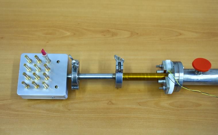
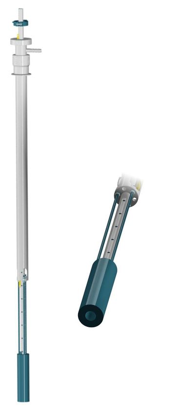
Figure 2. The probe cryomagnet, showing the yellow winding insulation. A
 header (white) was added to ease the insertion in the cryostat.

 In the following, the probe is described and tested in the DC
 regime, using a novel GaAs sample that shows quantization
 plateaus for a magnetic induction (5.5 T for the i = 2 plateau)
 lower than typical devices employed in metrology [7]. The results
 of the measurement are reported.
 When employed in the AC regime, the parasitic parameters of
 the device, the sample holder and the probe will shift the
 apparent resistance, measured at the end of the coaxial wiring,
 with respect to the quantized value. The minimization of this
 shift with the implementation of the multiple-series connection
 scheme is discussed.

 2. THE PROBE
 A simplified diagram of the probe assembly1 is shown in
 Figure 1. The small size of the probe allows the insertion in a
 standard dewar having a 50 mm port, such as transport dewars.
 2.1. Superconducting magnet
 The probe supports a superconducting magnet (see Figure 2)
 that can reach a field up to 6 T at 4.2 K when energized with a
 DC current of approximately 65 A. The field homogeneity is
Figure 1. A computer rendering of the cryomagnetic probe assembly: (left) 0.1% over a 10 mm length. The magnet includes a
side view; (right) front view, showing the magnet bore.
 superconducting thermal switch, which allows its operation in
 persistent mode.
impedance standards based on electronic fully-digital impedance
bridges [8], [14]-[16] associated to individual QHE devices 2.2. Probe insert
operating in a simple cryogenic environment. The probe holds a sliding insert. The bottom side of the insert
 The following describes the realisation of a cryogenic (Figure 3), which enters the magnet bore, mounts a TO-8 socket
environment for QHE devices, which includes a coaxial connected with nine coaxial wires2. Of these nine wires, eight are
cryogenic probe and a superconducting magnet of small size. The intended to be used on the current and voltage terminals of the
environment is suitable to perform QHE experiments at liquid device; the 9th wire is available for driving a section of the double
helium temperature of 4.2 K, and for an applied magnetic shield (see below).
induction up to 6 T, adequate for graphene QHE devices. Samples can be mounted on special TO-8 sample holders
 The probe will be employed with a new fully-digital coaxial (Figure 4) implementing a double-shielding technique [17] that
impedance bridge developed in [16]. The bridge is optimised to minimises the frequency dependence of the quantised Hall
perform RC comparisons with a 1:1 magnitude ratio, with a resistance caused by unwanted stray capacitances. The socket is
comparison uncertainty around 10-7. In combination with the wired with the inner conductors of the coaxial cables; the outer
probe, it will allow the calibration of a capacitance standard in conductors are connected to a common node very close to the
terms of RH and therefore the realisation of the unit of sample holder.
capacitance, the farad. The expected target relative uncertainty is The coaxial wiring (Figure 5) is terminated on a connection
2 × 10⁻⁷. box at the top of the insert (Figure 6) with isolated British Post

 1 The probe frame was fabricated by Graphensic AB, Sweden, according to 2 Lakeshore Ultra Miniature Coaxial Cable, type SC, Teflon insulation. The
INRIM specifications. wire has an outer diameter of 1 mm; the inner conductor has a series resistance
 per unit length of 0.282 Ω m-1 at room temperature; the inner to outer capacitance
 per unit length is 154 pF m-1.

ACTA IMEKO | www.imeko.org June 2021 | Volume 10 | Number 2 | 25
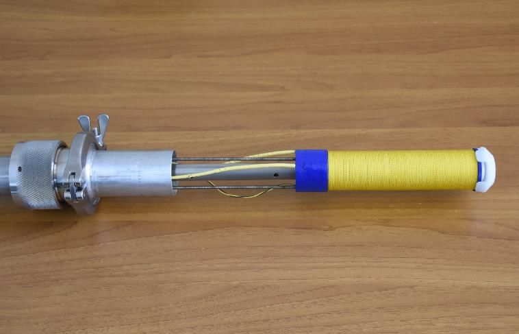
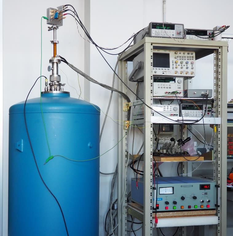
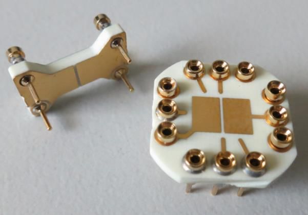
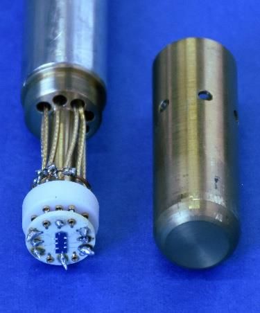
Figure 3. The bottom side of the insert, which slides into the cryomagnet
bore. (left) Diagram of the drum that supports the sample holder and hosts
the 9 coaxial connections. (right) Photo of the assembled probe: the brass
shield (right) has been removed to show the TO-8 socket, which hosts a GaAs
device on its TO-8 holder, and the 9 coaxial electrical lines.

Office Multiple Unit Steerable Array (BPO MUSA) coaxial
connectors. Often employed in impedance metrology, BPO-
MUSA connectors exhibit a good performance also in the DC
regime. The whole coaxial network composed of the device and
the wiring is completely isolated from the probe.
2.3. Operation
 Figure 7 shows the probe in operation. It is inserted into a
60 L liquid helium dewar. The magnet is energised with a DC
high-current power supply (Cryogenics PS 120A). A manual
current-reversing switch allows to reverse the magnetic field Figure 5. Schematic diagram of the coaxial connections of the probe. Nine
polarity. coaxial connections are available, fully isolated from the probe metal bulk.
 The outer conductors of each line are joined together on the sample holder
 The superconducting switch in parallel with the magnet is (pin 6).
driven by a DC laboratory power supply, which is turned off to
activate the persistent mode of operation. The persistent mode
maximises field stability and minimizes helium consumption, P151 is a 500 µm semi-insulating GaAs wafer on which a
since the magnet wires are unloaded, and can be used when GaAs-AlGaAs heterostructure was grown by Molecular Beam
performing precision measurements on a QHE plateau. Epitaxy (MBE). The wafer was cleaved in rectangles of
 7 mm × 3 mm, and 8 contacts (two current and six voltage
 contacts) were made by tin ball annealing. The contacts have a
3. TESTING
 resistance of about 10 mΩ.
 A test of the probe was made by performing measurement in P151 samples achieve a mobility of 58.5 T-1 and a carrier
the DC regime on a GaAs sample. concentration in the two-dimensional electron gas
 n = 2.67 × 10⁻¹⁵ m-2. This concentration corresponds to a i = 2
3.1. GaAs sample
 quantum Hall plateau at the magnetic induction
 The investigated sample, P151-24, was fabricated at the B = nh/ie = 5.5 T, where h is the Planck constant and e the
Physikalisch-Technische Bundesanstalt (PTB) facilities. Details electron charge. Such magnetic induction can be compared with
of the process can be found in [18]. the typical induction required by ubiquitous LEP samples [19],

Figure 4. TO-8 sample holders, implementing the double-shielding technique
[8], [17]. After the bonding of the quantum Hall device onto the holder (right),
the shielding cap (left) slids into the socket. Figure 6. The probe connection box.

ACTA IMEKO | www.imeko.org June 2021 | Volume 10 | Number 2 | 26
of about 9 T. Tests at T = 2.2 K and I = 39 µA show full
quantization to parts in 109, and a critical current density of
6 × 10⁻² A m-1 (30 µA over 0.5 mm) at T = 1.2 K [18]. At
T = 4.2 K, I = 77 µA, the relative deviation from the exact
quantization is about -0.6 × 10⁻⁶.
 The sample is mounted on an unshielded TO-8 holder with
soldered Pt wires.
3.2. Measurements
 The device is driven by a purpose-built, isolated and battery-
operated DC current source. The source can be manually
operated to deliver the current values I = 0 µA, ± 5 µA, ± 20 µA,
± 50 µA and ± 100 µA, and includes a fast protection circuit in
case of device thermal runaway. The DC voltage on selected
contacts is measured with a two-channel nanovoltmeter (Agilent
34420A).
 Figure 8 reports the outcome of the experiment. Figure 8(a)
is the graph of the Hall resistance RH(B) versus the applied
magnetic field B, measured with a current I = 20 µA. Figure 8(b)
shows the corresponding longitudinal resistance Rxx(B). Curves
obtained with increasing and decreasing B are shown; a little
hysteresis, related to the sweep rate (about 0.6 T min-1) can be
appreciated. Increasing the current up to I = 50 µA leads to
similar results (not reported). Figure 7. Overall view of the measurement setup for DC characterization. On
 In Figure 8(a) quantum Hall plateaux corresponding to filling the left, the liquid helium dewar, with the coaxial probe inserted. On the
factors i = 2 and i = 4 can be easily identified, and higher-index right, the rack of electronic instrumentation.
plateaux can be appreciated. Figure 8(b) shows the
corresponding Shubnikov-de Haas oscillations. On the i = 2
plateau, RH is flat over a range of about 0.2 T; the corresponding
Rxx is lower than 50 mΩ. The outcome of the experiment is
consistent with the expectations on a GaAs device.

4. AC QUANTUM HALL EFFECT
 In the DC regime the quantum Hall resistance is defined as a
four-terminal (4T) resistance [20]. If the 4T definition is applied
(no current is drawn from the voltage terminals by the
measurement setup) the cable errors are due to the wiring
parasitic conductances, which can be made negligible with
adequate isolation.
 In the AC regime, the four terminal-pair (4TP) impedance
standard definition is the most accurate [20, 21]. 4TP impedance
definition is however impractical for the quantum Hall
 (a) RH(B)
resistance. Since the output impedance of the voltage terminals
of a QHE device is of the order of RH, the parasitic admittances
of the cables give rise to very large errors at both the current and
the voltage terminal-pairs. Attempts to solve the problem by
triaxial connections and active guards were not completely
successful [22].
 The peculiarity of the quantized Hall state as a circuit element
[23] allows to exploit the so-called multiple-series connections [24].
Such connections redefine the quantum Hall resistance as a two-
terminal resistance (in the DC regime) or a two terminal-pair
(2TP) impedance (in AC) by keeping the magnitude of the cable
correction errors to very low values.
 In the DC regime, the behaviour of multiple-series
connections has been extensively considered [24], and dedicated
modelling tools for the electrical analysis of the connections are
available [25]-[27].
 In the AC regime, multiple-series connections have been also
implemented, although in a limited number of setups [3, 6-8]. (b) Rxx(B)
The connections schematics are shown in Figure 9. For the case Figure 8. Plot of the measured values of RH and Rxx versus the magnetic field
n = 1, no multiple-series schematic is employed, and the device B, for an applied current I = 20 µA. Blue line: increasing magnetic field. Red
is simply connected as a 2TP impedance with two coaxial leads. line: decreasing magnetic field.

ACTA IMEKO | www.imeko.org June 2021 | Volume 10 | Number 2 | 27
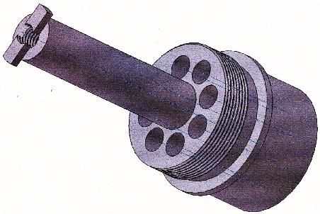
Table 1. Calculation of the real part of the relative error δZH occurring when
measuring a QHE device by using the n-series connections given in Figure 9,
for the frequency f = 1541 Hz. The calculation is given for two different
contact resistance values.

 Re[δZH] n RC = 10 mΩ RC = 10 Ω

 1 +1.0 × 10⁻⁴ +1.7 × 10⁻³
 -9
 2 -5.6 × 10 +1.4 × 10⁻⁶
 3 -1.1 × 10⁻⁸ -9.5 × 10⁻⁹

The case n = 2 and n = 3 are called double series and triple series,
respectively. Cases with n>3 can be conceived but are not
analysed here.
 The electrical modelling of multiple-series connections in the
AC regime is much more complex than the DC case, and yet to
be fully developed. Here, we apply an approximate model due to
Schurr et al. [28]. As can be seen from Figure 10, each coaxial
wiring is modelled as a T network with series impedance Zw
(mainly due to the series resistance of the inner conductor, which
can be relatively high – 1 Ω or greater – in cryogenic coaxial
leads) and a parallel admittance Yw (due to the cable capacitance
and loss); a contact resistance RC models the bonding and the
device junctions.
 The quantity of interest to be estimated is the relative
deviation δZH caused by the connections
 H − H
 H = , (1) Figure 9. n-series connection of a QHE device. (top) n = 1, no multiple-series
 H connection: the device is connected as a 2TP impedance by two coaxial leads.
 (middle) n = 2, double-series connection. (low) n = 3, triple-series connection.
where RH is the quantized Hall resistance, and ZH is the apparent
two terminal-pair (2TP) impedance as seen by a measuring
instrument at the extremes of the connections outside the The probe is ready to be employed with a fully-digital coaxial
cryostat. impedance bridge designed for the calibration of a capacitance
 The prediction of the model is standard in terms of RH with an uncertainty of a few parts in 107.
 In combination with the probe, the bridge is therefore suitable
 2
 w w c + w for the realisation of the unit of capacitance, the farad. The
 H ≈ [ +( ) ] . (2) effects of stray parameters will be minimized by exploiting the
 2 H
 triple-series connection technique, which reduces the connection
 The quantities Zw and Yw can be estimated from the cable errors to around one part in 108.
manufacturer specifications: in the following, the calculation is The probe is intended to be used with graphene single devices
done for a 1.7 m long Lakeshore Ultra Miniature Coaxial Cable and arrays [29], to be developed in the frame of the GIQS
and a 0.3 m long RG58 coaxial cable. project. In the meantime, the GaAs device here investigated will
The quantity RC is strongly dependent on the individual device allow to perform first tests of the bridge in operating conditions.
employed in the experiment, and to some extent it can also vary Measurements in the AC regime will be performed with a
for the same device in different cooling processes. We therefore fully-digital bridge [16], using the triple-connection series; the
computed the outcome of Equation 2 for two extreme cases, approximate electrical modelling of the connections reported in
namely RC = 10 mΩ and RC = 10 Ω. the paper predicts a maximum connection error of a few parts in
 Table 1 summarizes the result of the calculations performed 108. A more accurate modelling of such error, in progress, will
at the frequency f = 1541 Hz, which is of particular interest for allow to perform a correction of the measurement reading.
the realisation of the farad unit from the quantized resistance
[16]. It can be appreciated that, even for the case of a high contact
resistance, a triple-series connection reduces the measurement
error to about one part in 10 8. The triple-series connection will
be thus employed in the experiment. The residual error can be
corrected if accurate measurements of the stray parameters are
available.

5. CONCLUSIONS
 The test shows that the probe can be employed to reach the
quantization condition in Hall devices, and sensitive DC Figure 10 Electrical modelling of one of the connections to the QHE device.
measurements can be performed. In the AC regime, each connection is modelled as a T network with series
 impedance Zw and a parallel admittance Yw. The contact resistance RC models
 the bonding and the device junctions.

ACTA IMEKO | www.imeko.org June 2021 | Volume 10 | Number 2 | 28
ACKNOWLEDGEMENT [13] F. Overney, B. Jeanneret, Impedance bridges: from Wheatstone to
 Josephson, Metrologia 55(5) (2018), pp. S119–S134.
 GIQS: Graphene Impedance Quantum Standard is a Joint Research DOI: 10.1088/1681-7575/aacf6c
Project, code 18SIB07, of the European Metrology Programme [14] L. Callegaro, V. D’Elia, M. Kampik, D. B. Kim, M. Ortolano, F.
for Innovation and Research (EMPIR). This project received Pourdanesh, Experiences with a two-terminal-pair digital
funding from the European Metrology Programme for impedance bridge, IEEE Trans. Instrum. Meas. 64(6) (2015),
Innovation and Research (EMPIR) co-financed by the pp. 1460–1465.
 DOI: 10.1109/TIM.2015.2401192
Participating States and from the European Union's Horizon
 [15] J. Kucera, J. Kovác, A reconfigurable four terminal-pair digitally
2020 research and innovation programme. Regular updates assisted and fully digital impedance ratio bridge, IEEE Trans.
about the project are posted on the project webpage, Instr. Meas. 67(5) (2018), pp. 1199–1206.
ptb.de/empir2019/giqs/home/ and a LinkedIn group, DOI: 10.1109/TIM.2018.2790538
linkedin.com/groups/8824119. [16] M. Marzano, M. Ortolano, V. D’Elia, A. Müller, L. Callegaro, A
 LC and VdE thank Cristina Cassiago and Enrico Gasparotto, fully digital bridge towards the realization of the farad from the
INRIM, for helping with a first functionality test of the quantum Hall effect, Metrologia 58(1) (2021), art. 015002.
cryomagnet at the time of purchase. DOI: 10.1088/1681-7575/abba86
 [17] B. P. Kibble, J. Schurr, A novel double-shielding technique for ac
 quantum Hall measurement, Metrologia 45(5) (2008), pp. L25–
REFERENCES L27.
[1] Bureau International des Poids et Mesures, SI brochure, 9th DOI: 10.1088/0026-1394/45/5/N01
 edition, 2019. Online [Accessed 30 May 2021] [18] K. Pierz, B. Schumacher, Fabrication of quantum Hall devices for
 https://www.bipm.org low magnetic fields, IEEE Trans. Instr. Meas. 48(2) (1999),
[2] R. Ribeiro-Palau, F. Lafont, J. Brun-Picard, D. Kazazis, A. pp. 293–295.
 Michon, F. Cheynis, O. Couturaud, C. Consejo, B. Jouault, W. DOI: 10.1109/19.769586
 Poirier, F. Schopfer, Quantum Hall resistance standard in [19] F. Piquemal, G. Genevès, F. Delahaye, J. P.-. Andrè, J. N.-Patillon,
 graphene devices under relaxed experimental conditions, Nature P. Frijlink, Report on a joint BIPM-EUROMET project for the
 Nanotech 10 (2015), pp. 965–971. fabrication of QHE samples by the LEP, IEEE Trans. Instr.
 DOI: 10.1038/nnano.2015.192 Meas. 42(2) (1993), pp. 264–268.
[3] F. Lüönd, C.-C. Kalmbach, F. Overney, J. Schurr, B. Jeanneret, A. DOI: 10.1109/19.278562
 Müller, M. Kruskopf, K. Pierz, F. Ahlers, AC quantum Hall effect [20] L. Callegaro, Electrical Impedance: Principles, Measurement, and
 in epitaxial graphene, IEEE Trans. Instrum. Meas. 66(6) (2017), Applications, ser. Series in Sensors, CRC Press: Taylor and
 pp. 1459-1466. Francis, Boca Raton, FL, USA, 2013, ISBN 9781138199439.
 DOI: 10.1109/TIM.2017.2652501 [21] R. D. Cutkosky, Four-terminal-pair networks as precision
[4] M. Kruskopf, R. E. Elmquist, Epitaxial graphene for quantum admittance and impedance standards, IEEE Transactions on
 resistance metrology, Metrologia 55(4) (2018), pp. R27–R36. Communication and Electronics 83(70) (1964), pp. 19–22.
 DOI: 10.1088/1681-7575/aacd23 DOI: 10.1109/TCOME.1964.6539563
[5] A. F. Rigosi, A. R. Panna, S. U. Payagala, M. Kruskopf, M. E. [22] B. W. Ricketts, J. R. Fiander, H. L. Johnson, G. W. Small, Four-
 Kraft, G. R. Jones, B. Wu, H. Lee, Y. Yang, J. Hu, D. G. Jarrett, port AC quantized Hall resistance measurements, IEEE Trans.
 D. B. Newell, R. E. Elmquist, Graphene devices for tabletop and Instr. Meas. 52(2) (2003), pp. 579–583.
 high-current quantized Hall resistance standards, IEEE Trans. DOI: 10.1109/TIM.2003.810016
 Instr. Meas. 68(6) (2019), pp. 1870–1878. [23] B. W. Ricketts, P. C. Kemeny, Quantum Hall effect devices as
 DOI: 10.1109/TIM.2018.2882958 circuit elements, J. Phys. D: Appl. Phys. 21(3) (1988), art. 483.
[6] M. E. Cage, S. H. Shields, A. Jeffery, Initial NIST AC QHR DOI: 10.1088/0022-3727/21/3/018
 measurements, J. Res. Natl. Inst. Stand. Technol. 109(4) (2004), [24] F. Delahaye, Series and parallel connection of multiterminal
 pp. 391-405. Online [Accessed 10 June 2021] quantum Hall effect devices, J. Appl. Phys. 73(11) (1993), pp.
 https://nvlpubs.nist.gov/nistpubs/jres/109/4/j94cag.pdf 7914–7920.
[7] F. J. Ahlers, B. Jeanneret, F. Overney, J. Schurr, B. M. Wood, DOI: 10.1063/1.353944
 Compendium for precise ac measurements of the quantum Hall [25] M. Ortolano, L. Callegaro, Matrix method analysis of quantum
 resistance, Metrologia 46(5) (2009), pp. R1–R11. Hall effect device connections, Metrologia 49(1) (2012).
 DOI: 10.1088/0026-1394/46/5/R01 DOI: 10.1088/0026-1394/49/1/001
[8] J. Kucera, P. Svoboda, K. Pierz, AC and DC quantum Hall [26] M. Ortolano, L. Callegaro, Circuit models and SPICE macro-
 measurements in GaAs-based devices at temperatures up to 4.2 K, models for quantum Hall effect devices, Meas. Sci. Technol. 26
 IEEE Trans. Instrum. Meas. 68(6) (2019), pp. 2106-2112. (2015), art. 085018.
 DOI: 10.1109/TIM.2018.2882216 DOI: 10.1088/0957-0233/26/8/085018
[9] J. Schurr, F. J. Ahlers, G. Hein, K. Pierz, The ac quantum Hall [27] M. Marzano, T. Oe, M. Ortolano, L. Callegaro, N.-H. Kaneko,
 effect as a primary standard of impedance, Metrologia 44(1) Error modelling of quantum Hall array resistance standards,
 (2007), pp. 15–23. Metrologia 55(2) (2018), pp. 167–174.
 DOI: 10.1088/0026-1394/44/1/002 DOI: 10.1088/1681-7575/aaa5c1
[10] J. Schurr, V. Bürkel, B. P. Kibble, Realizing the farad from two ac [28] J. Schurr, F.-J. Ahlers, G. Hein, J. Melcher, K. Pierz, F. Overney,
 quantum Hall resistances, Metrologia 46, 6 (2009), pp. 619–628. B. M. Wood, AC longitudinal and contact resistance
 DOI: 10.1088/0026-1394/46/6/003 measurements of quantum Hall devices, Metrologia 43(1) (2006),
[11] J. Schurr, J. Kucera, K. Pierz, B. P. Kibble, The quantum Hall pp. 163–173.
 impedance standard, Metrologia 48(1) (2011), pp. 47–57. DOI: 10.1088/0026-1394/43/1/021
 DOI: 10.1088/0026-1394/48/1/005 [29] M. Kruskopf, A. F. Rigosi, A. R. Panna, D. K. Patel, H. Jin, M.
[12] L. Callegaro, Traceable measurements of electrical impedance, Marzano, M. Berilla, D. B. Newell, R. E. Elmquist, Two-terminal
 IEEE Instr. Meas. Mag. 18(6) (2015), pp. 42–46. and multiterminal designs for next-generation quantized Hall
 DOI: 10.1109/MIM.2015.7335839 resistance standards: Contact material and geometry, IEEE Trans.
 Electron Dev. 66(9) (2019), pp. 3973–3977.
 DOI: 10.1109/TED.2019.2926684

ACTA IMEKO | www.imeko.org June 2021 | Volume 10 | Number 2 | 29
You can also read