GUIDANCE, NAVIGATION AND CONTROL FOR THE ENTRY, DESCENT, AND LANDING OF THE MARS 2020 MISSION - NASA
←
→
Page content transcription
If your browser does not render page correctly, please read the page content below
(Preprint) AAS 17-031

     GUIDANCE, NAVIGATION AND CONTROL FOR THE ENTRY,
      DESCENT, AND LANDING OF THE MARS 2020 MISSION

                                            Paul Brugarolas*

              This paper presents an overview of the Guidance, Navigation and Control (GNC)
              system for the Entry, Descent, and Landing (EDL) phases of the Mars 2020
              Mission. The EDL GNC system adds Terrain Relative Navigation to the MSL
              EDL GNC system1 to enable landing on landing sites with landing hazards within
              the landing ellipse. This paper describes the GNC architecture, including sensors,
              actuators and algorithms, for the entry, parachute descent, and powered flight
              phases of the mission.

INTRODUCTION
   The Mars 2020 project is a rover mission in development with a projected launch date in the
summer of 2020 and landing on Mars in February of 2021. The main objectives of this rover
mission are to seek past life in Mars, collect rock samples for potential future return to Earth, and
prepare for humans.
   This mission extensively leverages the Cruise, EDL and Rover designs from Curiosity (2012).
The Rover (15% heavier than Curiosity) includes a new suite of science instruments tailored to the
Mars 2020 science objectives.
   The EDL GNC system is mostly built-to-print from MSL, but with some minor fixes and
enhancements. This paper is organized as follows, section 2 describes the hardware used by the
GNC system, section 3 describes the phases of EDL and subsequent sections will then describe the
GNC system for each phase of the mission focusing on changes from the MSL design1. The paper
concludes with a discussion on EDL impacts and a conclusion section.

*Mars 2020 GNC Chief Engineer, NASA Jet Propulsion Laboratory, California Institute of Technology, 4800 Oak Grove
Drive, MS 321-400, Pasadena, CA 91109-8099, USA.

                                                         1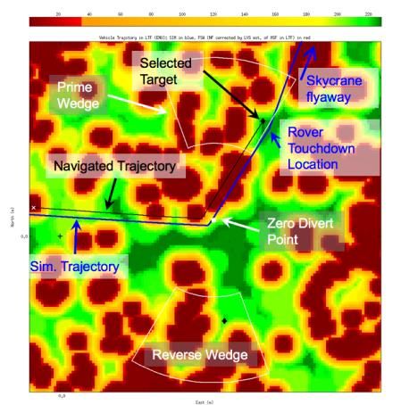
EDL GNC-RELEVANT HARDWARE
   On the Entry Capsule, shown on Figure 1, there can be seen two set of ejectable balance masses:
the cruise balance masses (two ~70 kg masses) and the entry balance masses (six ~23kg masses).
There are also, 4 pods of RCS thrusters with 2 thrusters each. These thrusters operate in blowdown
and regulated modes providing 170N and 250N per thruster respectively. The thrusters operate at
8 Hz in pulse width modulation mode with a commendable minimum on-time of 30 ms.

                                     Figure 1. Entry Capsule.

   Figure 2 shows the descent vehicle, which includes the GNC sensors. Two descent IMUs (each
has 3 DOF gyros and 3 DOF accels) and a landing radar also called Terminal Descent Sensor
(TDS). The TDS is a ka-band (35 GHz) Doppler radar with 6 narrow beam antennas (~ 3 deg
beamwidth). The TDS generates a single slant-range and ground relative velocity at 20 Hz. During
the different phases of flight, the TDS is re-configurable to enable selecting which antennas are
used during a given phase. The Lander Vision System (LVS) is a new GNC sensor added for Mars
2020. The LVS is composed of a ~90 FOV camera and a vision compute element within the rover
chassis. In addition, the descent vehicle has eight throttleable Mars Landing Engines (MLEs),
which can be commanded at 64 Hz and each can produce thrust in the range 300-3200N.

                                                  2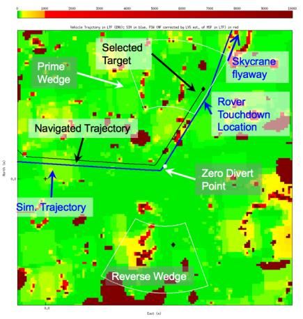
MLEs                                      DIMU-B

                                                                   DIMU-A

                                                                       TDS

                                                       LVS camera

                          Figure 2. Descent Vehicle and Stowed Rover

EDL PHASES
   Figure 3 shows the main phases of EDL. exo-atmospheric, entry, parachute descent and powered
descent phases.

                                     Figure 3. EDL phases

                                                3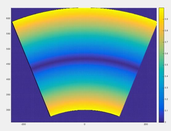
The Mars 2020 EDL GNC design is built-to-print from the MSL EDL GNC design except for:
   -     Fixing the touchdown velocity anomaly
   -     Changing the parachute deploy trigger to reduce the landing ellipse
   -     Adding Terrain Relative Navigation (TRN) to enable hazards within the landing ellipse
   We will discuss these changes during the phase that they occur.
   Each EDL phase has a different GNC system. The EDL GNC mode commander is a state
machine that precisely defines the behavior of the EDL GNC system over the entire EDL. It
specifies which GNC functions are performed at each mode and the conditions to transition
between modes, called mode triggers.

EXO-ATMOSPHERIC PHASE GNC
    During the exo-atmopheric phase of the mission, the vehicle will spindown (from the 12 RPM
of the cruise configuration) and turn to a predicted entry attitude to be ready for guidance start. In
addition, it will eject the cruise balance masses to create a CG offset that will generate a lift vector
during the entry phase. Figure 4 illustrates the block diagram of the GNC system during the
atmospheric phase.
       EDL Param Update:                        3-axis
            Pre-bank          Reference                       Attitude        Thruster
                              Attitude         Attitude                                    DRCS
        Ground Nav States                                    Controller        Logic
                                               Profiler
          Local Gravity

                                                             Navigation
                                                                                             DIMU
                                                               Filter

                                                            Cruise ACS
                                                            Attitude Init

                                   Figure 4. Exo-atmospheric GNC

    The EDL parameter update ground command provides a predicted bank command (pre-bank),
ground derived navigation states to seed the navigation filter and a local gravity correction to the
to the onboard J2 gravity model. The local gravity correction is new for Mars 2020. This parameter
was added to mitigate the MSL touchdown velocity anomaly.
    During this phase of the mission, the GNC system is three-axis attitude control system. The
reference attitude block is a 3-axis attitude commander, which creates the reference attitude from
the pre-bank and the predicted trim angle of attack at the beginning of entry guidance. The trim
angle of attack varies as a function of aerodynamic moments during the entry phase. The predicted
trim angle of attack is parameterized by entry speed. The entry speed provided by the navigation
filter is used to select the value to be used. The three-axis attitude profiler generates the typical
attitude profile (cancel rate, accelerate, coast, and decelerate phases). The entry controller
feedforward control path implements the attitude profile and the feedback control path (phase plane
controller) corrects for errors in tracking the profile by using attitude estimates from the navigation

                                                     4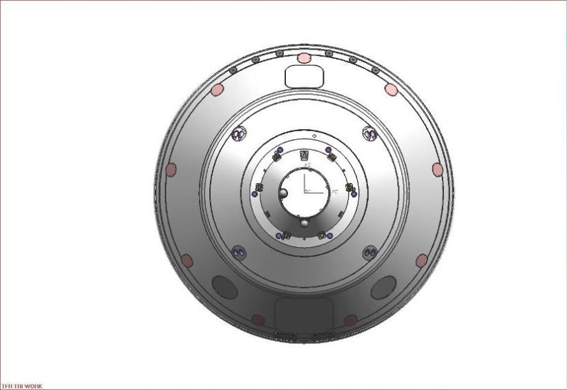
filter. The thruster logic generates the RCS thruster commands needed to get the torque requested
by the entry controller.
   At the predicted entry time, the vehicle pressurizes the RCS thrusters and then waits for the
entry guidance trigger (sense 0.2 g deceleration) to transition into the entry phase.

ENTRY PHASE GNC
   During the entry phase, an Apollo-derived entry guidance algorithm1 is used and has two main
phases: (i) range control and (ii) and heading alignment. The entry guidance algorithm generates
bank angle commands. These bank angle commands are of two classes: large bank angle command
changes when algorithms are first called or for bank reversals; and small bank angle corrections
during the range control and heading alignment tracking phases.

                                Bank           Reference     Attitude
              Entry                                                          Thruster
                               Profiler        Attitude                                    DRCS
             Guidance                                       Controller        Logic

                                                            Navigation
                                                                                             DIMU
                                                              Filter

                                          Figure 5. Entry GNC

   The entry GNC block diagram is shown in Figure 5. The guidance bank commands go to the
bank profiler, a single-axis attitude profiler, which will generate a slew profile for the large bank
commands. Then, the attitude commander will generate a reference 3-axis attitude by combining
the bank command with the predicted trim angle of attack. The predicted trim angle of attack is
scheduled based on entry speed. The reference attitude is then fed to the attitude controller, which
creates correction torques, by comparing with the estimated attitude from the navigation filter. The
desired torques are then implemented by the thruster logic.
   The entry phase concludes with the Straighten Up and Flight Right (SUFR) maneuver that
removes the angle of attack by ejecting the entry balance masses and rolls the vehicle to point the
TDS antennas towards the ground. For Mars 2020, we have changed the SUFR trigger and
parachute deploy triggers. We have changed the SUFR trigger from a velocity trigger to a velocity-
constraint downrange trigger.
    •   Trigger IF ([Vel < Vel_max AND Downrange < Downrange_threshold] OR [Vel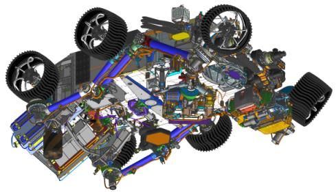
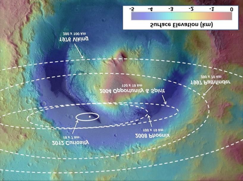
The change to a downrange trigger reduces the landing ellipse from 19x7 km (Semimajor x
Semiminor axis) to 8x7 km. Figure 6 shows a comparison of the Mars 2020 landing ellipse to
previous mars missions.

                                             Mars 2020
                                                8 x 7 km

Figure 6. Mars 2020 landing ellipse compared to previous missions (superimposed on the Gale crater
                                          elevation map)

PARACHUTE DESCENT PHASE GNC
    In this phase, the GNC goes back to RCS control to damp parachute induced attitude dynamics,
which are dominated by capsule swinging and coning under the parachute often denominated
parachute wrist mode. The block diagram in Figure 7 shows the reuse of the same navigation filter,
reference attitude commander, attitude controller, thruster logic as during entry but tuned for this
phase. However, because of concerns about RCS firings damaging the parachute, the attitude
controller is tuned to have very large deadbands. In this phase, after the vehicle reaches conditions
suitable for the heatshield ejection, it ejects the heatshield and then turns on the landing radar. The
main objective of the navigation filter in this phase is to continue propagating position and attitude
and also estimate ground relative position by using measurements from the landing radar.
   In this phase, Mars 2020 has added a new capability: Terrain Relative Navigation (TRN). This
capability allows to have hazards of about 100 m in size within the landing ellipse as long as hazards
are surrounded by hazard safe buffer zone of 120 m (60 m is the 99%-tile error in performing TRN).
   TRN is composed of two main parts: (i) a new sensor, the Lander Vision System2 (LVS)
composed of a camera and a vision compute element to provide map relative localization and (ii) a
Safe Target Selection (STS) to select a landing target from an on-board Safe Targets Map within a
reachable region.

                                                    6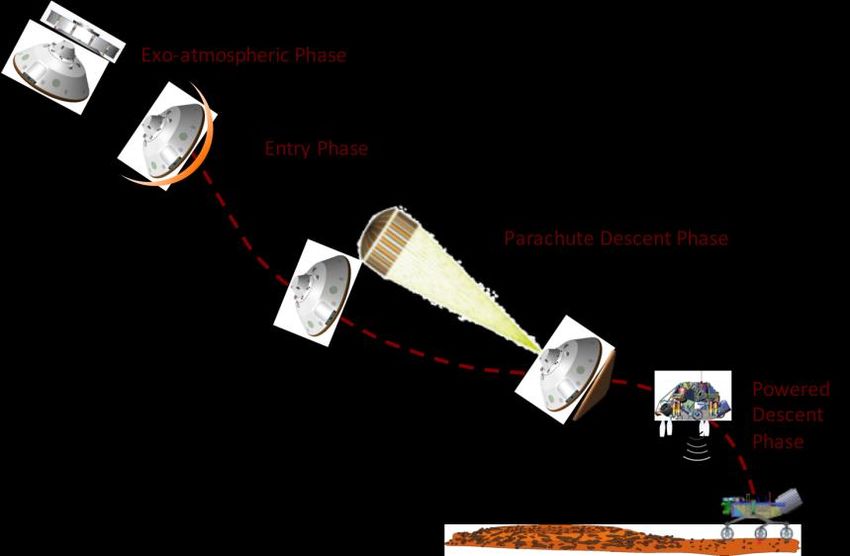
On Chute                Attitude                  Thruster
                     Reference                                                     RCS
                                            Controller                  Logic
                      Attitude

                                                                                  IMU
                                            Navigation
                                              Filter

                                                                                  RADAR

                                  Select                 MSF to Map
                            Safe Landing Target            Frame                  LVS
                                                          Estimation

             Figure 7. On-chute GNC (blue indicates the new elements added for TRN)

   After been initialized with a surface relative state, the LVS starts to perform map relative
localization at 4200 m above the ground and within 6 seconds produces a reduced performance
localization solution, which is accurate to 54 meters, and within 10 seconds produces a nominal
performance localization solution, which is accurate to 40 meters. When valid solutions are created
every 1 to 2 seconds, the GNC mode commander will update the Mars Surface Frame (MSF) to
Map Frame coordinate transformation.

Safe Targets Map
    The Safe Targets Map (STM) is an onboard map. It covers an area of 20x20 km over the landing
ellipse with a 10x10 m pixel resolution. Each pixel has a safe target level (0-255). The map size,
resolution and number of levels were selected to minimize memory use impact on the heritage MSL
design. The safe targets levels are assigned to indicate a landing risk (% landing failure risk) and if
the pixel has benign slopes (slope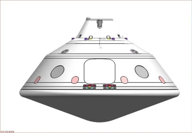
The Safe Targets Map is generated from the Mars 2020 Council of Terrain’s landing hazard and
slope maps. These two maps cover an area of roughly ~25x25 km, and have a resolution of 1x1
m/pixel. These maps are first transformed from a Lat/Lon grid to a Cartesian grid in the STM frame.
Then, the hazards and slopes are buffered by applying a padding kernel to account for TRN
knowledge and control errors. The padded hazard and slope maps are then coarsened to 10x10 m
pixels and used to assign the safe target levels for each pixel of the safe targets map.

Safe Target Selection
    The Safe Target Selection (STS) starts at the backshell separation trigger by computing the zero-
divert point. This point is then used to place the reachable regions (called wedges because of their
shape) on the STM. Figure 9 illustrates the shape of a wedge. The reachable wedge are
parameterized by a divert radius and azimuth from the zero-divert point and divert direction (e.g.
300 < radius < 635 meters and -25 < azimuth < 25 degrees). There are two wedges, that correspond
to divert directions associated with the MSL heritage backshell avoidance algorithm out-of-plane
vectors. Then, the algorithm searches each of the two wedges for the safest landing target pixel on
each one. If there are more than one pixel with the safest level it uses the following cost function

where, r center and azcenter define the center of the wedge with respect to the zero-divert point, and
the dr = 167.5 m and daz = 25 deg. define the size of wedge. The cost allows to aim for the center
of the wedge. The cost function has a penalty factor, fp, to penalize the weight of the azimuth term
on the cost. This cost allows to balance fuel use with backshell recontact risk. Note that fuel use is
proportional to divert distance, and backshell recontact risk increases with azimuth angle.
    To limit the computational loading of the flight computer the search is spread over 2.6 sec, while
the vehicle performs the activities to separate from the backshell. At the time to plan the backshell
avoidance divert, the prime wedge is defined by the out-of-plane-sign per the MSL heritage
Backshell avoidance algorithm. If the prime wedge best safe target is better than the one from the
reverse wedge, it selects it. If the reverse wedge best safe target is better than the one from the
prime wedge by more than a threshold, it will go to the reverse wedge. This allows to trade landing
risk with backshell recontact risk that is slightly higher for the reverse wedge.

       Figure 9. Reachable wedge and wedge cost function (fp = 0) evaluated at each location.

                                                    8
POWERED DESCENT PHASE GNC
The GNC block diagram for the powered descent phase is shown in Figure 10. The figure shows
a 6-DOF GNC system. The navigation filter fusions the TDS and IMU data to estimate altitude and
ground relative velocity. The powered descent guidance laws generate position and attitude
trajectory profiles. In addition, there are three controllers, a vertical position controller, a horizontal
position controller, and an attitude controller. The horizontal position control is achieved via the
attitude controller since the MLE are body fixed engines, which requires turning the vehicle to
achieve a horizontal motion. The engine mixing logic algorithm calculates the 8 MLE throttle levels
needed to achieved the commanded vertical force requested by the vertical loop and the
commanded torque requested by the attitude loop.
accMagPath
verticalPosPath +
+ Vertical + commandedZ-AxisForce
error Mass
Reference Position
Trajectory
- Controller accMagCorrection
attitudePath
commandedAttitude
Horizontal Engine
+ error + + Attitude MLE
horizontalPosPath Position Mixing
- Controller + - Controller
Logic
attitudeCorrection commandedTorque
attitudeEstimate
IMU
horizontalPosEstimate NAV
Filter
verticalPosEstimate
RADAR
Select
Safe Landing Target
Figure 10. EDLGNC Powered Flight Control Block Diagram (blue indicates the new element added
for TRN)
The main objectives of the powered descent phase are:
1. Perform the divert to the selected safe target while avoiding the backshell
2. Enable trajectory corrections that reduce altitude knowledge errors over time. Altitude
errors are due to radar measurement errors and to errors from measuring the terrain in the
vicinity of the landing site.
3. Perform the skycrane, detect touchdown and command the flyaway.
The first objective is achieved via the powered approach that performs a 300-635 m diverts out
of plane to evade the backshell. The second objective is achieved throughout via trajectory planing
capability at mode transitions (nominal) and when large errors are encounter (off-nominal). Figure
11 illustrates how the altitude errors are managed over time through the powered descent modes.
9MSL had an inflight anomaly during landing. MSL touchdown velocities were outside the
specified requirements. MSL vertical touchdown velocity was 0.63 m/s (Req. 0.75 ± 0.1 m/s), and
horizontal touchdown velocity was 0.18 m/s (MSL Req. 0 ± 0.1 m/s). The root causes were:
- Local gravity differed from onboard gravity model by -4.4 mm/s2. Which resulted in lower
than expected vertical velocity and contamination of horizontal velocity
- "Sandy radar" – MLE plumes created fast-moving dust which corrupted the radar
measurements. This led to increased horizontal velocity errors.
To mitigate the vertical velocity issue, Mars 2020 is adding a local gravity correction parameter to
the onboard gravity model. The NASA Mars program office has been developing a high-fidelity
Mars gravity map that will be used to derive this parameter.
In addition, to further mitigate the horizontal velocity issue, Mars 2020 has tightened the attitude
initialization requirement, also retuned the Navigation Filter to provide better filtering of the
suspect radar measurements. In addition, the horizontal requirement has been relaxed to 0 ± 0.4
m/s, which is within the MSL capability.
Figure 11. Altitude error management through the Powered Descent phase
10SIMULATION RUN
In this section, we show results form a simulation run from the GNC Simulation Test Set
(GSTS), which was upgraded from MSL to include a behavioral model of the LVS and prototype
code for the Safe Target Selection algorithm. Figure 12 shows birdes eye views of vehicle trajectory
over the STM and hazard maps.
Figure 12. Trajectory over STM and Hazard Maps
The figure has been annotated to indicate the zero-divert point, the prime and reverse wedges,
the navigated trajectory from FSW telemetry and the truth simulated trajectory. The errors between
the navigated and the truth trajectories motivates the need to buffer the hazards with the padding
kernel. By comparing the maps it can be observed the effect of the padding kernel which buffers
the hazards.
IMPACTS ON THE EDL SYSTEM
The range trigger could have an impact in EDL margins (parachute loads and parachute deploy
altitude loss) if the parachute deploy occurs at high or low velocities. However, velocity constraints
on the trigger limit these risks.
The addition of TRN required using up some of the MSL EDL excess margins. MSL landed
with 80 kg of fuel in the tank. The addition of TRN requires an additional 35 kg to be able to
perform the larger diverts. In addition, it tightens up the navigation filter requirements. In MSL,
the navigation filter needed to acquire the ground and converge by 3000 m altitude to trigger
priming of the MLEs. In Mars 2020, we now need the navigation filter to have converged by 4200
m to initialize the Lander Vision System. In MSL the radar had an excellent performance, the
navigation filter converged at 8.3 km altitude providing vast timeline margin to the 3000 m.
EDL and GNC are keeping watch on other key performance variables to guarantee that they
stay within the MSL design envelope. Example metrics include radar off-nadir angles and control
authority during the divert.
In addition, if TRN were to fail, there is graceful degradation. The Mars 2020 candidate landing
sites are approx. 90% safe, if TRN failed, the software will revert to the MSL divert and land there.
In this failed scenario, the risk of landing on a hazard will increase from approximately 0.5% to
10%.
11CONCLUSIONS
In this paper, we have provided a high level overview of the GNC design for the Mars 2020 mission
focusing on changes from the MSL heritage design. The fixing of the MSL touchdown velocity
anomaly, and the addition of two enhancements: the range trigger to reduce the lading ellipse and
Terrain Relative Navigation (TRN) to enable landing hazards within the landing ellipse.
These changes were architected in a way to minimize the impact to the MSL heritage hardware and
software. The addition of TRN required using some of the excess capability from MSL. Impacts to
EDL margins are small and the EDL system maintains healthy and balanced margins.
ACKNOWLEDGMENT
The research described in this article was carried out at the Jet Propulsion Laboratory, California
Institute of Technology, under a contract with the National Aeronautics and Space Administration.
Copyright 2017 California Institute of Technology. U.S. Government sponsorship
acknowledged.
REFERENCES
1
A. M. San Martin, G. F. Mendeck, · P. B. Brugarolas, · G. Singh, F. Serricchio, · S. W. Lee,· E.
C. Wong, and J. C. Essmiller, “In-flight experience of the Mars Science Laboratory Guidance,
Navigation, and Control system for Entry, Descent, and Landing”
2
A. Johnson, J. Chang, Y. Cheng, J. Montgomery, S. Schroeder, B. Tweddle, N. Trawny, J. Zheng,
“The Lander Vision System for Mars 2020 Entry Decent and Landing” in 40th ANNUAL AAS
GUIDANCE & CONTROL CONFERENCE. 2017. AAS 17-036.
12You can also read