ATC PACIFIC WATER HEATING INSTALLATION AND OPERATION MANUAL
←
→
Page content transcription
If your browser does not render page correctly, please read the page content below
ATC Electrical & Mechanical,
                            ATC House, Broomhill Drive, Tallaght, D24 EF99, Ireland
                             IE: 01 4678301, UK:0203 564 9164, Email sales@atc.ie

ATC PACIFIC WATER HEATING
INSTALLATION AND OPERATION MANUAL

W5-u    5 Litre Undersink water heater
W10-u   10 Litre Undersink water heater
W15-u   15 Litre Undersink water heater

                 5 Litre heater           10 and 15 Litre heaters

                           -1-
ATC Electrical & Mechanical,
                                                ATC House, Broomhill Drive, Tallaght, D24 EF99, Ireland
                                                 IE: 01 4678301, UK:0203 564 9164, Email sales@atc.ie
IMPORTANT SAFETY INSTRUCTIONS-READ BEFOR USING THIS WATER HEATER
1. This water heater must be earthed.
2. Locate & install this water heater only in accordance with the provided installation
   instructions.
3. Use this water heater only for its intended use as described in this manual.
4. This water heater should be installed by a qualified installer.
5. Do not operate this water heater if it is not working properly or if it has been damaged
   or dropped.
6. This water heater should be serviced only by qualified service personnel.
7. Failure to examine and if necessary, replace the anode rod at least once a year could
   cause the tank to fail and leak and void the warranty.
8. Cable connection should be to a 13A double-pole Switched Spur.
9. This water heater is not suitable for hard water areas unless a suitable water
   softener is fitted. In areas of hard water, failure to fit a water softener will cause
   premature unit failure and is not covered under warranty.
THESE INSTRUCTIONS SHOULD BE KEPT FOR FUTURE REFERENCE

1    Cold water Inlet         5   Heating indicator (5ltr)         9       Thermal insulation
                                  LED On/Off Switch (10 & 15Ltr)
2    Hot water Outlet         6   Outer cover                      10      Sacrificial Anode

3    Temperature adjustment   7   Electrical heating element       11      Cold water inlet

4    Cover Screw              8   High Level Thermal cutout

                                             -2-
ATC Electrical & Mechanical,
ATC House, Broomhill Drive, Tallaght, D24 EF99, Ireland
IE: 01 4678301, UK:0203 564 9164, Email sales@atc.ie
TECHNICAL SPECIFICATIONS
Product Code W5-U W10-U W15-U
Capacity Litres 5 10 14
Gallons 1.1 2.2 3.3
Power Watts 2000 2500
Voltage Volts 220-240
Frequency Hertz 50-60
Maximum Pressure Bar 8
Safety valve Max. Pressure Bar 6
Minimum Operating Pressure Bar 1
Connection Type 1/2” Male BSP
Distance Between Connections mm Center to Center 100
Thermostat Type Capillary type
Thermostat Range °C Min - °C Max 30-80 35-75
External Switch No Yes
Heating Indicator LED Yes
Installation location Undersink, wall mounted or
standing on rubber feet*
ERP Class B B
Heating Time (minutes) ΔT 35°C 7 13 15
ΔT 45°C 9 17 19
Dimensions Height 285 300 337
Width 240 340 364
Depth 240 330 354
IP Rating X4
Weight (kg) Empty 4.5 6.5 8
Full 9.5 16.5 23
* The ATC Pacific water heaters are supplied with Adhesive rubber pads to mount on the
bottom of the heater to allow them to stand rather than be wall mounted.
NOTE: The installer should review the contents of this manual with the owner on com-
pletion of the installation.
-3-ATC Electrical & Mechanical,
ATC House, Broomhill Drive, Tallaght, D24 EF99, Ireland
IE: 01 4678301, UK:0203 564 9164, Email sales@atc.ie
GENERAL WIRING DIAGRAM
HEATER MOUNTING INSTRUCTIONS
The water heater should be installed close to a water drainpipe so that excess water from
the safety relief valve can drain away without harm; this drain pipe should always be kept
free of obstruction.
Fix the mounting bracket supplied with the heater to the wall; see below for dimensions
of the holes required; always use screws that are suitable for the wall material and the
weight of the heater otherwise the heater may pull the bracket off the wall.
Hang the water heater on the bracket.
Tug downwards on the heater to ensure that both “fingers “of the bracket are seated in
the mounting slots.
The heater can also be stood on its base using the rubber feet provided for this purpose.
Attach the four adhesive feet to the base of the heater before plumbing.
Confirm water piping orientation before wall mounting.
45
66 45
14
Concrete or Brick Timber or Plaster
Hang the heater on the
Bracket
Note: If using the rubber feet, it is not neces-
sary to use the wall bracket also.
Should the installer wish to use the bracket as
an additional fixing method, confirm location
of bracket with feet attached to heater prior to
-4- installation.ATC Electrical & Mechanical,
ATC House, Broomhill Drive, Tallaght, D24 EF99, Ireland
IE: 01 4678301, UK:0203 564 9164, Email sales@atc.ie
WATER PIPE CONNECTIONS
All water connections to the heater must be made in copper pipe. If using Qualpex or
similar plastic piping method then a minimum of one metre of copper pipe must be
installed between the heater and the plastic piping system. All pipework between the
heater and the safety valve should be in copper and continue at least 1m from the water
heater.
Connect the cold-water inlet pipe to the inlet connection (marked with a blue ring) and
the hot water outlet pipe to the outlet connection (marked with a red ring). Dielectric
Connections are supplied and should be used as necessary.
The water heater is designed for connection direct to the incoming mains water supply
and accommodation must be made for the expanded water that will occur with each
operating cycle. Regulations permit expanded hot water to be accommodated within
the supply pipe work provided that an expansion relief valve is fitted (Check Local Reg-
ulations in your area). See drawing below.
For Inlet water pressure up to 4.1 bar.
Non Return
Pressure Release Valve*
Valve Supplied
With Unit Mains Water
Supply (MWS)
Hot out Cold in
Kit-C1
Service
To Drain Valve*
2.8m (5 &10 Ltr) or 4.2m (15 Ltr) is required for expansion in pipework between
cold water inlet and non return valve.
Where the expanded water cannot be accommodated in the pipe work due to space
restrictions and the static water supply pressure is under 4 bar, an expansion vessel
should be fitted in between the water heater and the safety relief valve.
Where static water pressures are likely to exceed 4 bar, fit a pressure reducing valve.
Note: In this case expansion using the mains is not permitted and an expansion vessel
must be used.
-5-ATC Electrical & Mechanical,
ATC House, Broomhill Drive, Tallaght, D24 EF99, Ireland
IE: 01 4678301, UK:0203 564 9164, Email sales@atc.ie
For Inlet water pressure up to 4.1 bar
where expansion in the mains is not Pressure Release
possible . Kit-A1 Valve Supplied
With Unit
Non Return
Valve*
Hot out Cold in MWS
Kit-C1
Service
To Drain
Valve*
For Inlet water pressure over 4.1 bar.
Note: If a pressure reducing Pressure Release
valve is used then allowing for Kit-A1 Valve Supplied
expansion in the pipework is
not possible. An expansion With Unit
Non Return
vessel must be used.
Valve*
Hot out Cold in MWS
Kit-C1
Kit-B1
Service
To Drain
1: Available as accessory
Valve*
5, 10 or 15 Ltr *:From Plumbing Merchant
Water heater
CLOSED SYSTEM THERMAL EXPANSION
There is a Pressure relief safety valve supplied with the water heater, the pressure relief
outlet will allow a little water to escape when heating due to expansion of the water in
the tank.
It is recommended to pipe this waste to a tun-dish (Kit-C) and then to waste. The safety
valve has been pre-set in the factory to 6 bar, please do not adjust.
The Pressure Relief safety valve should be tested by twisting the top in an anti-clockwise
direction until water flows out of the waste outlet; It is recommended that pressure relief
valves are tested at least once every six months, especially to reduce leakage caused by
the buildup of minerals and corrosion.
-6-ATC Electrical & Mechanical,
ATC House, Broomhill Drive, Tallaght, D24 EF99, Ireland
IE: 01 4678301, UK:0203 564 9164, Email sales@atc.ie
When water is turned off, reverse flow should be prevented using an appropriate non
return valve. This is to prevent the element from operating without water in the tank.
Note: The outlet of the Pressure relief valve should be kept free of obstruction; it should
be installed with the outlet pointing down and plumbed to waste. A tun dish (Kit-C) is
available for this purpose
A 2 Ltr. Expansion vessel (Kit-A) and a Pressure Reducing Valve (Kit-B) are also avail-
able as optional accessories.
ELECTRICAL CONNECTION
All ATC Pacific water heaters come pre-wired with 1.5mm2 2 core and earth. The heater
should be connected by a suitably qualified electrician in accordance with IEE wiring
regulations.
A suitable termination to the fixed wiring of the premises must be provided adjacent to
the heater using a suitably rated double pole disconnection switch with a minimum of
3mm contact gap and protected by an appropriately rated circuit breaker or RCD.
If this heater is installed in a bathroom it must be supplied from a circuit that is protected
by a high sensitivity RCD with a maximum rating of 30mA.
OPERATING INSTRUCTIONS
• The water heater can be used by children of at least 8 years (as well as by per-
sons with reduced physical, sensory or mental capabilities, or lack of experience or
required knowledge) provided that they are under supervision, or after they have
been instructed relating to the safe use and have understood the potential dangers.
• Children should not play with the water heater.
• Cleaning and maintenance must be performed by the user and not by unsupervised
children.
• Children of less than 3 years should be kept away unless continuously supervised.
• Children aged from 3 years and less than 8 years shall only switch on/off the water
heater provided that it has been installed in its intended normal operating position
and they have been given instruction concerning use of the heater in a safe way and
understand the hazards involved, children should always be supervised.
• Children aged from 3 years and less than 8 years shall not plug-in, regulate, clean the
water heater or perform maintenance.
• Before connecting the water heater make sure that the voltage is the same as indi-
cated on the device rating label.
• Do not use in presence of gas, inflammable or explosive liquids or substances as
defined in BS5345.
Start Up and Testing
Before connecting the power, fill the tank and system with water and check all the plumb-
ing for leaks. Ensure that all air is out of the water system; open the hot water taps before
-7-ATC Electrical & Mechanical,
ATC House, Broomhill Drive, Tallaght, D24 EF99, Ireland
IE: 01 4678301, UK:0203 564 9164, Email sales@atc.ie
opening the service valve, open the service valve until constant water flows from the hot
outlet. Once water is flowing, close the hot water tap. Failure to carry out this step can
crack the lining of the heater and result in leaks.
To start the heating cycle:
Make sure tank is full of water, otherwise damage to the water heater may occur.
For the 10 and 15 Litre heaters turn the switch on and then follow the 5Ltr instruction
below.
For the 5 Litre heater, turn the temperature adjustment knob clockwise to 3/4 maximum
and the indicator light will come on to show the element is heating. The indicator light will
remain on until the temperature setting has been reached, at which point the light will go off.
When the temperature drops below the set point of the thermostat the indicator light
will automatically come back on. This is a “pilot light” indicating the unit is in the heating
process.
To Set the Temperature.
After the water heater has reached the set point outlined above check the water tempera-
ture — do not place hands directly under water outlet as there could be a risk of scalding.
If it is necessary to adjust thermostat turn the dial clockwise to increase the temperature
and anti-clockwise to decrease it.
PERIODIC MAINTENANCE AND PARTS REPLACEMENT
Maintenance should only be carried out by a qualified service person.
Note: For most of these operations the power supply should be turned off and the water
will have to be drained from the heater.
Draining the Heater
1. Isolate the power supply.
2. Shut off water inlet valve.
3. Remove water heater and invert over a sink to allow water to drain from tank safely.
Removing the Heating Element
1. Turn off power supply and drain the heater (see previous section).
2. Remove the cover screw and cover.
3. Disconnect electrical cables attached to element.
4. Unscrew the heating element retaining nuts and remove compression bracket.
5. Remove the element.
De-scaling the Heating Element
Scale deposits can dramatically affect the heating efficiency of the element. Heavy scale
can even cause the element to burn out. The element can be descaled either chemically
or manually:
1. Remove heating element (see previous section)
2. Soak the element in white vinegar or other descaling solution. Once descaled, rinse
-8-ATC Electrical & Mechanical,
ATC House, Broomhill Drive, Tallaght, D24 EF99, Ireland
IE: 01 4678301, UK:0203 564 9164, Email sales@atc.ie
the element well with fresh water, OR,
3. Once the element has dried up, use a soft brush (nonmetallic to prevent damaging
the stainless-steel sheath) on element, and brush the dried mineral off.
4. Check and replace anode rod as required, (see below).
5. Reinstall the element with gasket and make the electrical connections.
6. Reinstall the water heater as per above normal installation procedure.
7. Refill tank with water before restoring power.
Changing the anode rod
The anode rod helps protect the tank against corrosion. The magnesium anode rod
needs to be inspected and changed every year.
Galvanic and electrolytic corrosion can be caused by non-municipal water supplies or
low-level stray electrical currents in the water heater.
Galvanic and electrolytic corrosion can destroy a tank and can cause dirty water. If this
happens examine the anode rod immediately.
Rapid degradation of the anode rod (less than 1 year) may indicate the presence of gal-
vanic corrosion or high acidity/alkalinity in the water supply.
To replace the Anode:
1. Turn off the power supply and drain the heater (see previous section).
2. Remove heating element (see previous section).
3. Remove the spent anode from the element by twisting the spent anode anti-clock-
wise and replace it with a new anode rod.
4. Replace heating element (see previous section).
5. Reinstall the water heater and refill tank with water before restoring power.
Changing the thermostat
1. Turn off power supply.
2. Remove cover screw and cover. Remove dial from outside of cover.
3. Disconnect the spade connection wires on the on thermostat.
4. Remove and retain rubber plug holding the capillary sensor in the element and re-
move capillary bulb.
5. Unscrew and remove the screws holding the thermostat to the cover.
6. Install new thermostat and re-attach wiring and screws.
7. Re-install the capillary sensor into the sensor pocket hole in the element and install
rubber plug into top of the sensor pocket.
8. Re-install cover and cover screw and reinstall adjustment dial.
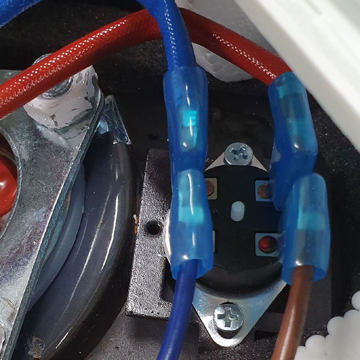
Resetting the high-level thermal cutout
Occasionally the high-level thermal cutout may trigger and shut the water heater down.
This occurs when water temperature exceeds 93°C, at this temperature the high-level
thermal cutout will shut off power to the heating element.
-9-ATC Electrical & Mechanical,
ATC House, Broomhill Drive, Tallaght, D24 EF99, Ireland
IE: 01 4678301, UK:0203 564 9164, Email sales@atc.ie
5 Litre Hi Level Reset 10 and 15 Litre Hi Level Reset
To reset the High Level Thermal cutout:
1. IMPORTANT: Disconnect heater from electrical power.
2. Remove the cover screw and cover.
3. Firmly press reset button (see above) and listen for a “click”.
4. Replace the cover and cover screw.
5. Reconnect power.
6. IMPORTANT: Check the operation of the thermostat, turn temperature dial from high
to low, if the red light does not go off on low setting, turn off the power supply, and
call a qualified service person to replace thermostat.
7. If the system works, please set thermostat to desired setting.
Note: a lower setting is more economical, and reduces the risk of scalding.
CAUTION: Call a technician if the high limit needs to be reset frequently.
TROUBLESHOOTING
Water does not heat up
1. Make sure the power supply is on and there is power available.
2. If light does not come on, check that the reset button is pushed in; follow steps from
previous section.
3. If the indicator light works properly but the temperature does not get hot at the tap,
test for a plumbing crossover. Shut off cold supply to heater and open hot water tap.
There should be no water flowing. Any continued flow indicates a crossover which
will affect the temperature and will need to be corrected.
4. Replace heating element (see previous section on changing the heating element).
-10-ATC Electrical & Mechanical,
ATC House, Broomhill Drive, Tallaght, D24 EF99, Ireland
IE: 01 4678301, UK:0203 564 9164, Email sales@atc.ie
Indicator Light not on
1. If the light does not come on, but water gets hot, check for faulty bulb.
2. Check reset button; follow steps from previous section.
Brown water
1. Brown or rusty water indicates a “spent” anode rod. Replace anode rod.
Odor in water
1. Smells from the water are usually due to an unusual reaction between local water
and the heater’s anode, check anode rod.
This usually occurs on non-municipal water supplies.
Water is too hot
1. Turn the temperature selector dial counter anti-clockwise to lower temperature.
2. If temperature does not change then replace the thermostat.
No Water flow
1. Check service valve is open and ensure minimum operation pressure is above 1
bar.
Note: This water heater is not suitable for use on gravity fed systems.
Unit Leaking
1. Check water connection fittings at the top of tank, ensure the connections to the
water heater are sound and are not the cause of the leak; if they are leaking, tighten
the connections.
2. Inspect heating element gasket for cracks or perishing if there are any signs of
damage replace element and gasket together.
NOTE: Elements and Gaskets should always be replaced together; do not reuse an
old gasket.
WARRANTY
ATC Electrical and Mechanical provides a two year limited parts warranty for the ATC
Pacific water heaters as long as the unit has been installed, used and maintained in ac-
cordance with the information provided in this manual. For full terms and conditions of
sale and warranty please see www.atc.ie.
In order to arrange parts for the heater, the information listed below is required. It is recom-
mended to write this information below and keep this instruction manual in a safe place.
Serial Number: Date of Manufacture:
Date of Purchase: Location Purchased:
-11-ATC Electrical & Mechanical,
ATC House, Broomhill Drive, Tallaght, D24 EF99, Ireland
IE: 01 4678301, UK:0203 564 9164, Email sales@atc.ie
ERP RATING INFORMATION
Model W5-U W10-U W15-U
Storage volume (V) L 5 10 14
Declared load profile XXS XXS XXS
Water heating energy efficiency class B B B
Water heating energy efficiency (ηwh) % 32.0 32.0 32.0
Annual electricity consumption (AEC) kWh 576 576 576
Sound power level (LWA) dB 15 15 15
Daily electricity consumption (Qelec) kWh 2.781 2.781 2.781
Mixed water at 40°C (V40) I --- --- ---
Thermostat temperature settings of the wa-
°C 75 65 65
ter heater, as placed on the market
(Waste Electrical & Electronic Equipment)
(Applicable in the European Union and other European
countries with separate collection systems)
This marking shown on the product or its literature, indicates
that it should not be disposed of with other household
wastes at the end of its working life.
To prevent possible harm to the environment or human
health from uncontrolled waste disposal, please separate
this from other types of wastes and recycle it responsibly to
promote the sustainable reuse of material resources.
Household users should contact either the retailer where
Packing List: they purchased this product, or their local government of-
1 Water heater fice, for details of where and how they can take this item for
environmentally safe recycling.
1 Mounting Bracket
4 Adhesive rubber feet Business users should contact their supplier and check the
1 6 Bar Pressure Relief Valve terms and conditions of the purchase contract. This product
1 Instruction Manual should not be mixed with other commercial wastes for
disposal.
2 Dielectric Connectors
1 Bag of fixings
-12-You can also read