VITALink Armored 2 Hour Fire Resistive Circuit Integrity Coaxial Cable - Comtran Cable
←
→
Page content transcription
If your browser does not render page correctly, please read the page content below
VITALink® Armored 2 Hour Fire Resistive Circuit
                     Integrity Coaxial Cable

                              INSTALLATION GUIDE
                               For 6 AWG Armored
                          2 Hour Fire Resistive Applications

c(UL)us 75°C Listed Type CMR
Armored
For use in Electrical Circuit Integrity
System FHIT.40C & FHIT7.40C
R27557, (72v)

Installation Guide Dated May 2021
Table of Contents
SCOPE ...................................................................................................................................................... 1
INTRODUCTION ........................................................................................................................................ 1
ELECTRICAL CIRCUIT INTEGRITY SYSTEM FHIT.40C and FHIT7.40C ............................................................... 1
DESIGN/SYSTEM/CONSTRUCTION/ASSEMBLY USAGE DISCLAIMER............................................................. 3
TOOLS REQUIRED FOR TERMINATION ........................................................................................................ 4
PULLING CALCULATIONS .......................................................................................................................... 4
        Maximum Allowable Pulling Tension .................................................................................................. 5
        Back Tension...................................................................................................................................... 6
BEND RADIUS CALCULATIONS .................................................................................................................. 6
INSTALLATION DETAILS .............................................................................................................................. 7
   1.      CABLE SUPPORT .............................................................................................................................. 7
   2.      WALL OR FLOOR ASSEMBLY: ........................................................................................................... 8
   3.      FIRE RESISTIVE CABLE: ...................................................................................................................... 8
   4.      SUPPORTS: ...................................................................................................................................... 8
   5.      ADDITIONAL INFORMATION: ......................................................................................................... 10
   6.      ARMOR REMOVAL ........................................................................................................................ 11

   330A Turner Street, Attleboro, MA 02703 • (P) (800)-842-7809 • (F) 508-399-8839 • www.comtrancorp.com
SCOPE
VITALink® Armored 2-Hour Fire Resistive Circuit Integrity Coaxial Cable is a unique coax which
offers superior fire endurance capabilities along with the well-established benefits & features
associated with NEC Type CMR cable designs. This coaxial cable is specifically designed to
meet the circuit integrity requirements in NFPA 72 National Fire Alarm and Signaling Code,
as well as other low voltage critical circuits in NFPA 70 National Electrical Code.
INTRODUCTION
The following instructions are for the VITALink® Armored 2-Hour Fire Resistive Circuit Integrity
Coaxial Cable for UL 2196/ULC S139 Electrical Circuit Integrity System No. FHIT.40C &
FHIT7.40C. The National Electrical Code, Canadian Electrical Code, and all applicable rules
and regulations, including federal, state, or provincial, local, and municipal or territorial laws
should be followed.
ELECTRICAL CIRCUIT INTEGRITY SYSTEM FHIT.40C and FHIT7.40C
Electrical Circuit Integrity Systems consist of components and materials that are intended
to provide protection for specific fire alarm and control wiring systems with respect to the
circuit integrity upon exterior fire exposure. The specifications for Electrical Circuit Integrity
System No. FHIT.40C and FHIT7.40C and its assembly are all important details in the
development of the ratings.
Ratings apply only to the entire integrity system assembly, constructed using the
combination of components specified in the system. Individual components and materials
are designated for use in a specific system(s) for which corresponding ratings have been
developed and are not intended to be interchanged between systems. Ratings are not
assigned to individual system components or materials.
The Electrical Circuit Integrity System No. FHIT.40C and FHIT7.40C must be fastened to a
concrete or masonry wall or a concrete floor-ceiling assembly. The fire rating of wall or floor-
ceiling assembly must be equal to or greater than the rating of the electrical circuit integrity
system. This is to ensure that the complete electrical circuit integrity system will survive during
the fire and hose stream exposure.
The Electrical Circuit Integrity System No. FHIT.40C and FHIT7.40C is evaluated by the fire
exposure and water hose stream test as described in the Standard UL 2196/ULC-S139. The
system contains the construction details of the tested configuration. The conductor size,
cable type, and voltage rating, etc. are construction details that are also provided. Cables
are listed to NEC and CEC Types and constructed to:
• c(UL)us -Type CMR to UL 444 harmonized with CSA C22.2 No. 214
330A Turner Street, Attleboro, MA 02703 • (P) 800-842-7809 • (F) 508-399-8839 • www.comtrancorp.com
1The Electrical Circuit Integrity System No. FHIT.40C and FHIT7.40C was tested with steel-strut
supports. The hardware, clamps, strut, etc., unless otherwise noted, are to be made of steel
so that these components do not melt in fire. No substitution to the equipment listed in the
system is allowed.
The supports are an important part of The Electrical Circuit Integrity Systems No. FHIT.40C and
FHIT7.40C, with Hose Stream Test. The maximum distance between the supports is listed in
the system and should not be exceeded. The type of support and the distance between
the steel supports is unique to that specific system and is for all sizes/types of cable unless
otherwise noted in a specific system.
The VITALink® Armored Coaxial Cable was tested in both horizontal with offsets configurations
and vertical configurations and the support mechanisms are detailed in the system.
Compatibility of support materials used in Electrical Circuit Integrity System No. FHIT.40C and
FHIT7.40C is also a concern. Bare copper should not be in contact with hot dip galvanized
cable tray or supports.
This system shall be installed in accordance with all provisions of the National Electric Code
and/or the Canadian Electric Code, as applicable to location, and as amended by the
details of each individual system (such as type of supports and distance between supports).
NOTE: Authorities having jurisdiction should be consulted in all cases as to the specific
requirements covering the installation and use of these classified systems.
330A Turner Street, Attleboro, MA 02703 • (P) 800-842-7809 • (F) 508-399-8839 • www.comtrancorp.com
2The following instructions are for the VITALink® Armored 2-Hour Electrical Circuit Integrity System
FHIT.40C and FHIT7.40C. These requirements must be followed to maintain the 2-Hour rating in
a fire rated area. It is assumed that the installation was properly designed. Comtran
Engineering support should be contacted for questions not addressed in the instructions.
DESIGN/SYSTEM/CONSTRUCTION/ASSEMBLY USAGE DISCLAIMER
• Authorities Having Jurisdiction (AHJ) should be consulted prior to construction and in
all cases as to the particular requirements covering the installation and use of UL
Certified products, equipment, systems, devices, and materials.
• Fire resistance assemblies and products are developed by the design submitter and
have been investigated by UL for compliance with applicable requirements. The
published information cannot always address every construction nuance
encountered in the field.
• When field issues arise, it is recommended the first contact for assistance be the
technical service staff provided by the product manufacturer noted for the design.
Users of fire resistance assemblies are advised to consult the general Guide
Information for each product category and each group of assemblies.
• Only products which bear UL/CSA Marks are considered Certified.
The following cables are approved for use in Electrical Circuit Integrity System No. FHIT.40C
and FHIT7.40C.
Nominal Nominal
Approximate
Part Number of Nominal Core Armor Jacket
Net Weight
Number Conductors Diameter (in/mm) Diameter Diameter
(Lbs/1000 Ft)
(in/mm) (in/mm)
36691 1 0.792”/20.119 1.070”/27.178 NA 725
36692 1 0.792”/20.119 1.070”/27.178 1.170”/29.718 839
COMTRAN VITALink®1/C 6 AWG 75C c(UL)us CMR CERTIFIED FIRE-RESISTIVE CABLE FOR USE
IN FHIT & FHIT7 ELECTRICAL CIRCUIT INTEGRITY SYSTEM #40C. SEE UL FIRE RESISTANCE
DIRECTORY R27557 (MONTH/YEAR).
330A Turner Street, Attleboro, MA 02703 • (P) 800-842-7809 • (F) 508-399-7004 • www.comtrancorp.com
3TOOLS REQUIRED FOR TERMINATION
PULLING CALCULATIONS
When installing the cable, the maximum pulling tension on the conductors and on the full
cable should not be exceeded. When the cable is pulled around a bend, it is in contact
against the inner arc of curvature of the bend. If any substantial amount of pulling force has
been developed in the cable, the friction load due to the pressure at this point will greatly
surpass that due solely to the weight of the cable. Thus, bends in the run increase the pulling
load significantly. Factors that shall be considered prior to installation, to minimize the
possibility of cable damage, are as follows:
• Tensile strength of the conductors
• Method of attachment to the cable
• Sidewall pressure
• Estimated pulling tension
• Force required to pull the cable off the reel
• Coefficient of friction between the cable and adjacent surfaces
• Bend radius
330A Turner Street, Attleboro, MA 02703 • (P) 800-842-7809 • (F) 508-399-7004 • www.comtrancorp.com
4Maximum Allowable Pulling Tension
The maximum allowable pulling tension on the cable(s) is the lesser of the maximum
allowable tension based on conductor strength, the maximum allowable tension based on
sidewall pressure, and the limit based on the attachment method to the cable.
Max Pull
Strength Value in lbs.
1 Conductor 210
*see IEEE 1185 for additional information on Pulling Calculations.
Cable Attachment Limit
When attaching to the cable it is important to apply equal tensions to the conductor and the
armor simultaneously. The attachment methods and/or ropes used to pull the cable must be
rated for the applied force. Recommended method of pulling coaxial cable is by the basket
weave type pulling grip applied over the outer sheath. Maximum pulling tensions are based
on this pulling method. Do not exceed the maximum pulling tensions.
Sidewall Pressure
When a cable is pulled around a bend, radial force is exerted on the insulation, armor, and
jacket as the cable is pressed against the inner arc of the bend. This is referred to as sidewall
pressure and is expressed as pounds per foot of radius.
Sidewall pressure is important in cable pulling calculations for two reasons. The first is its increase in the
total pulling tension due to greater pressure between the cable and the bend. The second is its
crushing effect upon the cable insulation and the possibility of permanent damage to the insulation
and/or the cable armor if excessive sidewall pressures are permitted. Sidewall pressure is usually the
determining factor when establishing maximum allowable pulling tension for large conductor sizes.
330A Turner Street, Attleboro, MA 02703 • (P) 800-842-7809 • (F) 508-399-7004 • www.comtrancorp.com
5The maximum value for sidewall pressure depends on the cable design. For VITALink®
Armored Coaxial Cables it is normally 200 pounds per foot of bend, with a 10-times pulling
radius multiplier. Under certain circumstances it may be necessary to reduce the bend radius
multiplier to 8 times (which is for permanent training). For this case, the sidewall pressure
should be reduced accordingly.
Back Tension
The force required to pull a cable off the reel is generally referred to as back tension. This is
normally taken to be zero since the cable is fed off the reel. This value may be negative, and
light braking may be applied to control the flow of cable to avoid feeding at too great a
rate. For downward pulls, considerable braking may be required.
BEND RADIUS CALCULATIONS
In establishing the minimum allowable bend radius for a cable, one must consider that two
distinct cases occur. There are bends which occur during pulling (in which case the cable is
under tension and is subsequently straightened after leaving the bend) and a bend made as
part of the permanent training in position (in which case the cable is not under tension and is
usually only bent once). Obviously, for pulling cable under tension, the radius should be as
large as practical to minimize the danger of flattening the armor or other damage occurring.
For permanent training, when no subsequent straightening or re-bending is required, the
minimum allowable radius can be smaller. Guidelines for the minimum permissible radius of
bend have been established for these conditions:
1) The minimum training radius is used where no tension is applied to the cable (i.e.,
permanent training), and
2) The minimum pulling radius is used where tension is applied to the cable.
Values recommended for bend radii are provided in the following table.
Note, bend radius is measured from the inside portion of the cable.
VITALink® Armored Coaxial Cable — Minimum Bend Radius of Cable
Conductor Size Normal Overall Min. Bend Radius (In)/(mm)
Part # Diameter
(AWG)
(In)/(mm) Training Pulling
36691 6 1.070”/27.178 8.5”/215.9 10.7”/271.78
36692 6 1.170”/29.718 9.4”/238.8 11.7”/297.18
330A Turner Street, Attleboro, MA 02703 • (P) 800-842-7809 • (F) 508-399-7004 • www.comtrancorp.com
6INSTALLATION DETAILS
1. CABLE SUPPORT
For cables installed in non-fire rated areas install per the NEC or CEC. For cables installed in
fire rated areas, see limits for UL System 40C.
When transitioning from a straight run of VITALink® Armored cable to a bend, use additional
supports at the start of the bend and the end of the bend as shown below.
For VITALink® Armored cables, cable shall be secured within 12 inches of boxes, cabinets, fittings, or
other cable terminations. It is recommended that support systems be completed as soon as possible
after the cable is installed. Fasten the cable at the far end of the installation and work back toward
the reel, straightening as you go. Straighten by hand if possible, do not use tools such as a hammer or
screwdriver, since this may deform the armor. Although not required, forms made from preformed PVC
conduit bends cut in half may be used as a guide when forming bends. Make sure the minimum bend
radius is observed.
330A Turner Street, Attleboro, MA 02703 • (P) 800-842-7809 • (F) 508-399-7004 • www.comtrancorp.com
7Bend in small increments, do not try to make the entire bend in one operation, shape into
final position gradually. When bending multiple cables at the same place, shape the inner
cable and form the other cables to this one. This will provide uniform curves. Do not leave
long lengths of cable in a manner that will subject cable to point stresses. If a long length
of cable is left hanging unsupported, the cable may be damaged before connection is
completed.
Cables should not be held under tension after installation and some slack is desirable in the
region of the terminations. In open installations, the cable must be adequately supported
to prevent undue strain on the cable and the termination.
2. WALL OR FLOOR ASSEMBLY:
Minimum 2 hour rated concrete or masonry wall or concrete floor. Opening in wall or floor
through which raceway passes is to be sized to closely follow the contour of the raceway.
Through-opening in wall or floor shall be fire stopped using an approved firestop system.
See Through-penetration Firestop Systems (XHEZ) for presently certified firestop systems.
3. FIRE RESISTIVE CABLE:
The 2-hour fire rating applies to Coaxial Armored cable passing completely through a fire
zone and terminating a minimum of 12 inches beyond the fire rated wall or floor bounding
the fire zone. The cables, as identified below, may be installed in the vertical or horizontal
orientation.
COMTRAN - VITALink® Brand Type c(UL)us CMR Armored Coaxial Cables with or without an
Overall Jacket. To be installed as described herein and in accordance with the
manufacturer’s installation instructions dated May 2021.
4. SUPPORTS:
Supports - Min 12 gauge, by 1-1/2-inch-wide or 1-5/8-inch-wide, painted, or unpainted,
slotted steel channels with hemmed flange edges. Channel bottom with or without holes.
Lengths of slotted steel channels 5 feet and less shall be secured to the wall or floor with a
min of two 1/4-inch diameter (or larger) by 2-1/4-inch min long concrete screws, or 1/4-
inch diameter (or larger) by 1-3/4-inch-long min steel masonry anchors. One screw or
anchor to be located at each end of the slotted steel channel. Lengths of slotted steel
channel in excess of 5 feet require a min of three screws or anchors, one at each end of
the channel and one centrally located within the length of the channel.
330A Turner Street, Attleboro, MA 02703 • (P) 800-842-7809 • (F) 508-399-7004 • www.comtrancorp.com
8A. Trapeze-type Supports – When the cable is installed
on/from trapeze-type supports, the trapeze-type supports
shall be secured from the surface of the floor. The supports
shall be spaced a maximum of 4 feet on center.
B. Clamps − For armored jacketed VITALink® coaxial
cables, both vertical and horizontal installations,
Kindorf®† J-800 series interlocking strap with
Kindorf®† J-851 locking brackets shall be used
(Figure 2). The inside diameter of each interlocking
strap shall be sized to correspond with the outside
diameter of the cable, to provide a secure mount
with the strap of the clamp in complete
contact with the outside of the cable.
B2. Clamps − In lieu of item B only for VITALink® Type
Armored cable without an outer jacket, in both vertical
and horizonal installations, a two-piece single bolt type
pipe clamp, or one piece, saddle type pipe clamps (not
shown), sized to correspond with the outside diameter of
the cable (Figure 3). The clamp shall provide a secure
mount to the strut without deforming the copper armor.
NOTE: For vertical cable installations, the supports shall be spaced a maximum of
6 feet on center. For horizontal cable installations using steel struts, the supports shall
be spaced a maximum of 4 feet on center.
330A Turner Street, Attleboro, MA 02703 • (P) 800-842-7809 • (F) 508-399-7004 • www.comtrancorp.com
95. ADDITIONAL INFORMATION:
General procedures for terminating are provided below. Be advised that Comtran cannot be
responsible for the effectiveness of a termination because we have no control over the
fabrication of these items.
The environment should be clean and dry. Tools should be in good working order and used
for the purpose that they are designed. Terminating materials must be high quality and be
compatible with the cable.
As shown in the following section, remove the armor from the end of the cable a sufficient
distance to allow separation of the conductor, provide the necessary length to connect to
the equipment being used. Any underlying tapes and fillers should then be removed.
• In removing this material, care should be taken not to damage any underlying layer,
particularly the cable insulation.
• Install the connector per manufacturer’s instructions. Connections to enclosures should be
through the use of connectors approved for use with copper armored cable in the
particular environment that it is installed.
• Strip the insulation from the conductor for a distance necessary to connect the equipment
per the equipment manufacturer’s instructions. Care should be taken to avoid cutting,
nicking, or scoring of the conductor.
• Apply compression terminal lugs or connectors per manufacturer instructions. When using
a compression connector, a calibrated, properly sized compression tool should be used.
• Use proper hardware and tightening torque to connect the terminal lugs.
330A Turner Street, Attleboro, MA 02703 • (P) 800-842-7809 • (F) 508-399-7004 • www.comtrancorp.com
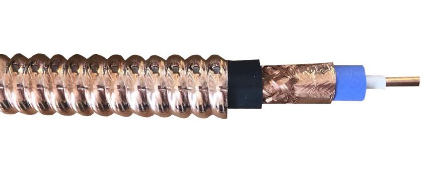
106. ARMOR REMOVAL
1. Mark where the armor is to be cut by
wrapping tape around the cable as a
guide. Use a tubing cutter to cut the armor.
The cutting wheel should be adjusted at the
crest of a corrugation and rolled back and
forth in ever increasing arcs while
advancing the wheel until a 360-degree
turn can be made without the tool
wobbling off track.
2. If required, mildly flex the cable until the sheath
parts at the cut.
3. Slightly rotate sheath back and forth while
pulling to remove sheath. Do not rotate
completely around. If present, filler cord may
be entangled. When present, remove tape
and filler cord. Remove any burrs. Install the
connector according to the connector
manufacturer’s instructions.
For longer lengths, armor may be removed in
sections.
330A Turner Street, Attleboro, MA 02703 • (P) 800-842-7809 • (F) 508-399-7004 • www.comtrancorp.com
11You can also read