FIX ROAD & FIX STRAP cargo securing systems - Operating Instruction Manual - NWE Network ...
←
→
Page content transcription
If your browser does not render page correctly, please read the page content below
FIX ROAD® & FIX STRAP®
    cargo securing systems
      Operating Instruction Manual

NWE NETWORK ENGINEERING OY AB    VAT: FI 09628099        1
Uppstutåget 2                   Tel: + 358 622 50 114
FIN-64200 Närpes, FINLAND       www.nwe.fi info@nwe.fi
Introduction
Please ensure you read these instructions and understand them fully and that you
have been trained in the use of the system by a competent person before using FIX
Road lashing systems. If you are in any doubt please refer to your Safety Officer for
advise before proceeding. Your ‘FIX Road’ or ´FIX Strap´ lashing systems has been
specially produced for you by NWE Network Engineering, specialists in cargo control
systems for Road and Sea.
When correctly used, all FIX lashing systems give a very high degree of load
restraint. With FIX the cargo is ‘over-lashed’, securing it to the cargo bed and making
it unitized with the vehicle load platform. In addition to this the FIX system is kind to
sensitive cargoes as FIX distributes the lashing load evenly across the entire contact
surface of the cargo thus reducing damage though point loading that can sometimes
occur when using a 50mm webbing lashing for example.
The FIX Road can be operated without mounting the vehicle load platform. The entire
lashing operation can be conducted from ground level therefore re-moving the
inherent dangers of mounting the vehicle load platform and other risks involved such
as throwing a lashing over a load to an unseen side.

Operating Instructions
Your FIX Road system is a specially reinforced high tensile strength tarpaulin that is
suspended at roof height on a bungee/roller system running in rail the length of the
load platform. The FIX can be supplied as a full-length system (single-element) or in
several individual sections (multi-element). The FIX is fitted with 50mm webbing
lashing straps at 1.3m intervals along its length to which ratchet tensioner will be
attached during the lashing process for securing the load. Fixed winches can also be
suitable. When the system is not in use, the bungee cords pull the FIX tarpaulin or
straps up to roof height automatically to make a clear loading space and then the
system is pulled back to the rear of the trailer. This position will be called the ‘Stowed’
position for the purpose of these instructions.
At no time should the ratchet tensioner be left attached to the lashing straps when
the FIX is being pulled along is rail or when in the stowed position. Prior to
commencement of loading ensure that all the elements of the system are drawn to
the opposite end of the vehicle to which loading will commence. This would normally
mean that the FIX system should be pulled back to the rear of the vehicle to ensure
the maximum width aperture is available for loading. In certain circumstances,
however you might wish to review this procedure. Do not load through hanging
straps. The lashing procedure can be approached in 2 ways.

Loading and FIX Road positioning:
1) With either a single or multi-element FIX Road system in the stowed position to the
front of the trailer, normally loading would commence from the front bulkhead end
and continue rearwards. Once loading is complete, the FIX system or elements
thereof may be drawn over the top of the load. This is done by pulling one of the
yellow pull cords where fitted or one of the lashing straps. The FIX system will follow
on its roller rails to the position you require.
2) Where a multi-element system is used, the FIX Road systems may also be
individually positioned over the load progressively as loading proceeds.

           NWE NETWORK ENGINEERING OY AB             VAT: FI 09628099                  2
           Uppstutåget 2                            Tel: + 358 622 50 114
           FIN-64200 Närpes, FINLAND                www.nwe.fi info@nwe.fi
3) Multi-element FIX Road system can also be ready pulled over the cargo space
before loading begins. Then special care has to be taken to avoid FIX or its parts to
get pulled away with the cargo or the forklift.

Loading procedure:
1) Where possible load the cargo evenly with similar height cargoes at either side of
the platform. This will ensure the most effective and secure method of lashing. If any
items are placed in a position where the FIX will not make significant top contact with
the load, then they will not be properly secured. Take care to avoid this eventuality.
Ensure that no sharp objects are left protruding where the FIX is due to come down
and cover. Any sharp object it comes into contact with will cut and damage the FIX
system and will affect is lashing strength capability locally.

2)

The FIX is now ready for lashing.
Always commence the lashing procedure by tensioning both ends of the cargo first.
The reason is to secure the cargo from moving forward or backward. When lashing a
‘Single-element’ FIX always continue the lashing procedure at the lowest point of the
cargo and work outwards from either side. When using a ‘Multi-Element’ FIX you
additionally have a possibility to do the tensioning in sections. The first and the last
pair of lashing lines can be mounted so that a necklace is formed like in picture
below. Then the lashing line should be at max. 45degrees. Only use approved
lashing points that tolerate the lashing angle. The rest of the lashing lines should be
as straight down as possible to maintain the lashing force caused by pre-tensioning.
Never make the lashing at an angle when securing to the rave as the hook will slip
along and the strap will become lose. Only where the tensioner is attached to a fixed
lashing ring (captive) the lashing strap may be inclined. Attach the ratchets to the
FIX’s lashing webbings (usually orange). A tensioner is required at each side of the

           NWE NETWORK ENGINEERING OY AB            VAT: FI 09628099                 3
           Uppstutåget 2                           Tel: + 358 622 50 114
           FIN-64200 Närpes, FINLAND               www.nwe.fi info@nwe.fi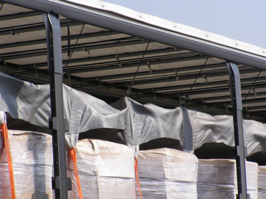
FIX. Pull the loose end of the lashing webbing through the slot in the ratchet barrel
until all the slack is taken up. Once the FIX makes good contact with the top of the
cargo, commence initial ratchet tightening. Repeat this operation sequentially on
either side, do not over tension at this stage. The object of this initial lashing
procedure is to ensure the FIX is evenly positioned at both sides of the cargo with
initial tension applied. Make sure that when doing this the maximum amount of
webbing is pulled through the ratchet to avoid the tensioner barrel to fill up
prematurely and jam the tensioner before the webbing strap has tightened
sufficiently. Finally tidy lose cords and lashing webbing ends to ensure they are
secure and do not trail.

Unloading:
There is a need for caution prior to commencement of releasing any lashings. Check
beforehand that there has been no movement of the load as releasing the lashing
may allow parts of the load to fall out. This might cause injuries or damages.

           NWE NETWORK ENGINEERING OY AB           VAT: FI 09628099                     4
           Uppstutåget 2                          Tel: + 358 622 50 114
           FIN-64200 Närpes, FINLAND              www.nwe.fi info@nwe.fi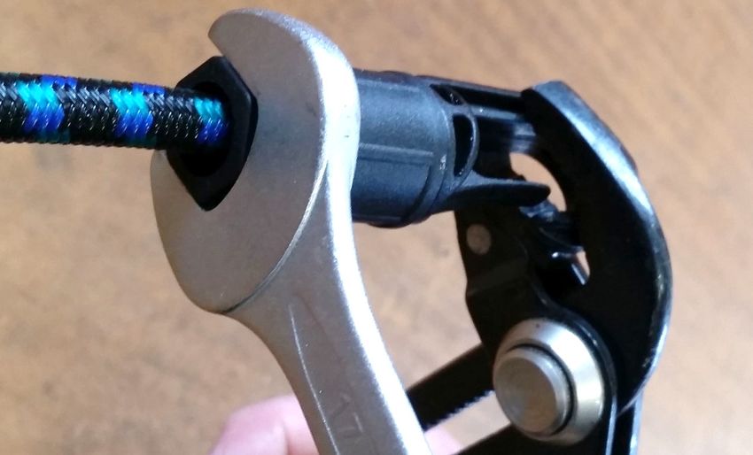
In normal circumstances, however, with the FIX system correctly engaged, your load
will arrive in a stable and secure condition. In these circumstances, the unloading
procedure is the reverse of the loading procedure. It is important to remember that
when the lashing has been released, the tensioner end must be removed from the
FIX lashing strap webbing end before sliding back the FIX. There is a good reason
for this; the strap end will swing outward if the tensioner end is still attached when
sliding the FIX on its rails. A heavy metal tensioner swinging freely could badly injure
anyone who is in the proximity of the vehicle.

Care and checks:
Always ensure your FIX system is correctly stowed for the current circumstances. If
left in the wrong position when load or unloading, the lashing straps can be caught up
in the load or e.g. fork lift and either damage the system and/or cause a serious
accident.
     − The FIX system should be visually inspected before and after each use
     − If your FIX system has sustained any damage it must be reported to your
         supervisor.
     − Damaged straps and tensioner equipment should be replaced.
     − Damage to the FIX must be inspected
     − Faulty or damaged equipment should not be used.
     − NEVER lashing onto a collapsible cargo
     − Always use an appropriate tensioner.
     − Never tie off the lashing straps instead of using a tensioner.
     − Never load through hanging straps.
     − The FIX and or its straps must not come in contact with sharp or abrasive
         objects
     − Always ensure the lashings are perpendicular when lashing to the rave.
         NEVER lash at an angle unless to approved captive lashing rings.
     − Only use approved lashing points

           NWE NETWORK ENGINEERING OY AB            VAT: FI 09628099                 5
           Uppstutåget 2                           Tel: + 358 622 50 114
           FIN-64200 Närpes, FINLAND               www.nwe.fi info@nwe.fi
− Ensure loose ends of webbing and tie cords do not trail. Ensure the are tidy
     and secure.
   − Do not attempt to continue your journey or undo your lashings if you suspect a
     shifted load
   − NEVER leave tensioners attached when in stowed or positioning mode

This operating manual has been prepared on the assumption that good working
practice and a sensible approach will be adopted by the operator. It attempts to cover
many of the operational aspects relating to the system that may be experienced on a
day-to-day basis but cannot predict every eventuality that may be encountered.
Correct use of the equipment is essential at all times and a common sense approach
to its use and operation is expected. Any misuse, abuse, damage, incorrect or
unauthorized use of the equipment will be the entire responsibility of the operator.
This equipment must only be used by personnel that have read and understood this
manual and have received training on how to operate the system correctly and
safely.

           NWE NETWORK ENGINEERING OY AB          VAT: FI 09628099                6
           Uppstutåget 2                         Tel: + 358 622 50 114
           FIN-64200 Närpes, FINLAND             www.nwe.fi info@nwe.fi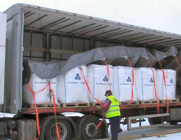
FIX STRAP Technical description

FIX Strap is an ordinary lashing strap including the strap, the ratchet short end and
some extra parts to make it more versatile and easier to use than normal loose
straps.
FIX Strap extra parts consists of a bungee suspension system, which lifts the strap
up to the roof while not in use, and the parts needed to attach the bungees to the
strap. At the roof there is the same rail system as with FIX Road.
At one side of the truck (the same side you decide to have the
hook of the long part of the strap) the strap is attached to the
bungee with FIX Slide. The strap is thread through FIX Slide like
in the picture. Do not thread the strap any other way as then the
adjustment is more difficult and tension in the strap when
tightened will deform FIX Slide. Place it roughly 5-15 cm closer to
the hook than the height of the cargo space.

The other end of the bungee is attached to another FIX Slide, but
here the strap is thread only once through the lower (larger) opening.
After loading the hook at the long end of the strap is placed in a
lashing point at the rave by pulling the strap down tensioning the
bungee cord. The bungee tension will keep the hook on place while
tensioning, which makes it easier, faster and safer to ensure
the hook stays in the place. The ratchet short end is placed
and tightened as normally. The strap will slide through the FIX
Slide until the strap is tightly around the cargo. The ring is so
large that the other bungee can slide trough it if the load is
very low.
When unloading the cargo, and loosening the ratchet, the
bungees will pull the strap up to the roof again and it can be sliding out of the way.
The advantages of the FIX Strap system are:

- straps can be easily pulled to right position
- hooks will stay in place during loading operations
with the tension of the bungee cord
- bungees will pull the strap out of the way when
released for unloading
- uses ordinary standard 50mm straps which allows damaged straps to be replaced
- same FIX Strap can be tuned in for different inner heights
- same roller and suspension system as in FIX Road, makes easy upgrade possible

           NWE NETWORK ENGINEERING OY AB             VAT: FI 09628099                    7
           Uppstutåget 2                            Tel: + 358 622 50 114
           FIN-64200 Närpes, FINLAND                www.nwe.fi info@nwe.fi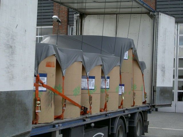
Assembly instructions for the FIX Road® and FIX Strap® systems

Before you start:
   • Mounting of the rails in FIX Load Securing system should be done by two
      persons to improve result and avoid injuries.
   • The rails need to be mounted as high as possible with the opening facing
      inwards.
   • Check that eventual moving roof, side curtain and beams etc. has enough
      space for the operation and make sure eventual locking device and side doors
      can move freely.

Installation:
   1. Drill holes in the profile with a distance of 750 mm center to center (figure 11).
       A) When mounting on a vertical surface use wall mounting brackets like in
       drawing above.
       B) If the rails are mounted on horizontal surface (roof sticks), use different
   brackets. Then the length of the rails may need to be cut acc. to mounting
   possibilities. Brackets are mounted on every second or every third roof stick
   depending on which suits better with approximately 750mm distance from each
   other.

Drawing 11. Wall mounting brackets and a wider joint bracket over the track joint.

           NWE NETWORK ENGINEERING OY AB           VAT: FI 09628099                  8
           Uppstutåget 2                          Tel: + 358 622 50 114
           FIN-64200 Närpes, FINLAND              www.nwe.fi info@nwe.fi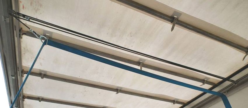
Drawing 12. Wall brackets and locking nut at end of track.

   2.     Mount the first bracket at the end of one side of the truck. Use screws or
        rivets to mount the brackets. Rivets must be of a folding type (Monobolt).

        Drawing 13. Note that bracket mounting must not disturb other functions in the beam.

   3.    Lift the rail into position and support it.

   4.     Mount the other brackets on place. The rails are supplied in 6m or 6,7m
        sections. You will note that one end of each rail is slightly more flared than the
        other which is more square. This is a natural aspect of all cold rolled section. It
        is important to match the ends together when making a smooth coupling. So
        ensure square to square, flare to flare. This way you will make the best joint
        and allow the carriage assembly to run smoothly through it. When installing
        the rails, the flared end should be to the front of the trailer to allow for square
        to square to be together at the main join of the 6m sections. The final piece
        should be installed to the end of the second 6m section, flare to flare. Rail
        joints are covered with a special wider bracket. At rear a 'get-out' section
        should be allowed for by stopping the rail about 100mm short of the full trailer
        length to allow for the introduction and removal of the roller carriages.

    5. Properly tighten all screws on brackets.

    6. Note! Check that the brackets are securely mounted before mounting the
      roller carriages.

    7. Start mounting the roller carriages into the rails.

a) Before introducing the bungee carriage units into the rail release the tension of the
bungees by unclipping the snap hook from the nose of each carriage. Once safely in

            NWE NETWORK ENGINEERING OY AB               VAT: FI 09628099                 9
            Uppstutåget 2                              Tel: + 358 622 50 114
            FIN-64200 Närpes, FINLAND                  www.nwe.fi info@nwe.fi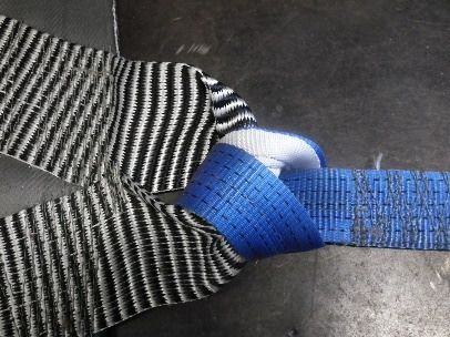
the rail, pull the carriage assemblies well onto the length off the rail and then
reconnect. Substantial tension is then accumulated within the system when the
bungees are reconnected so take special care ensuring the roller carriage does not
roll back and escape the rail ends during installation as the sudden realize force can
be substantial and could cause injury.

b) The carriage frame is cranked. Ensure the crank is facing down when installing.

c) Ensure the bungees are not twisted or tangled together.

The elastic cords should run parallel and not cross nor curl around each other. This
should be done so that one person holds the roller carriage in place on one side
while the other person mounts the
roller carriage on the other side.
Please take care that the roller
carriages don’t escape from the rail
while mounting them on the other
side. The tension in the suspension
lines can cause injuries if the roller
carriages escape.

                         Picture 14. Correct position of roller carriage and bungees.

   8. As the roller carriages are mounted, push them towards the front of the trailer.
      Place the roller carriages evenly along the length of the rails.

   9. Fasten a locking bolt (M8 x 12 DIN 933 Hex Cap Screw with Nylon Insert Lock
      Nut) to both ends of the rails to stop the roller carriages from escaping (Figure
      15).

                Drawing 15. Locking bolt and last wall bracket mounted.

   10. The Fix fabric is received folded. Spread out the fabric with the tag for the type
       code to the rear of the trailer as seen in figure 16. The tag for the type code
       must always be accessible in the rear of the trailer.

           NWE NETWORK ENGINEERING OY AB            VAT: FI 09628099                  10
           Uppstutåget 2                           Tel: + 358 622 50 114
           FIN-64200 Närpes, FINLAND               www.nwe.fi info@nwe.fi
Figure 16. Spread out the Fix fabric with the tag to the rear of the trailer.
Figure 17 & 18. Tag for
the type code tells (from top down) the size and model of the cover,
production month and year, serial number, DEKRA approval number, number of straps
and strap length . Tag for strap tells breaking strength BS, lashing capacity LC,
material, length, applied standard and manufacturer.
Lift the Fix fabric up and then attach the suspension lines to the metal rings on
the Fix as seen in figure 19.
11. Start with the suspension lines in the rear of the trailer and move on towards
the front as seen in figure 20. The tag for the type code should be found in the
rear of the trailer.
Figure 19. Attaching the bungee rope to the Fix with the plastic hook.
Figure 20 & 21. Work from the rear to the front of the trailer.
NWE NETWORK ENGINEERING OY AB VAT: FI 09628099 11
Uppstutåget 2 Tel: + 358 622 50 114
FIN-64200 Närpes, FINLAND www.nwe.fi info@nwe.fiNote! The Fix fabric should be lifted and not the suspension lines pulled down all the
way to avoid injuries caused by the tension in the lines.
12. When the system is not in use the bungee cords pull
the FIX tarpaulin up to roof height automatically and
then it can be pulled to one end of the body to make
a clear loading space. This is the ‘Stowed’ position
(figure 22).
Figure 22. Fix tarpaulin in stowed position.
Mounting of FIX Strap
FIX Strap uses the same tracks and bungee suspension system as FIX Road.
Instead of attaching bungee cords to the FIX Road fabric as above, the bungee cords
are attached on both sides to FIX Slide, which supports the lashing strap.
On the hook side the strap is thread
through FIX Slide like in the pictures.
Do not thread the strap any other
way as then the adjustment is more
difficult and tension in the strap
when tightened will deform FIX
Slide.
Adjusting the height is easiest to do
so that the strap is pushed through the FIX Slide from both sides at the same time
and then adjusting the loop size of the strap before pulling it out again.
The free end (on ratchet side) the strap can slide freely through
the lower (larger) opening of FIX Slide. It does not matter which
way the strap is thread through if it is only going through FIX Slide
once. Now the strap will slide easily through on one side of the
vehicle and will be adjusted to fixed position on the other side so it
can be attached to the rave and will stay there with bungee force
while the other side is tensioned. It is not allowed to load or
unload through hanging straps. They must be drawn completely clear of loading /
unloading aperture.
NWE NETWORK ENGINEERING OY AB VAT: FI 09628099 12
Uppstutåget 2 Tel: + 358 622 50 114
FIN-64200 Närpes, FINLAND www.nwe.fi info@nwe.fiScrew hooks assembly
Tools needed:
17mm FLARE NUT wrench or 17mm standard wrench
Pliers
Hook parts: hook and locking nut
Place the bungee through the nut and into the hook.
NOTE! The threads inside the nut towards NOTE! The bungee need to reach all the way.
the free end of the bungee cord.
Take a steady grip of the hook. Screw on the nut by hand until it stays correctly on the
threads.
When hand force is not
enough, take a steady
grip of the hook with
pliers and turn the nut
with wrench until the nut
is completely on place.
NWE NETWORK ENGINEERING OY AB VAT: FI 09628099 13
Uppstutåget 2 Tel: + 358 622 50 114
FIN-64200 Närpes, FINLAND www.nwe.fi info@nwe.fiSome options might become handy.
Figure 23. Replacement strap Figure 24. & 25. Adjustable hook and how the strap is routed
NWE NETWORK ENGINEERING OY AB VAT: FI 09628099 14
Uppstutåget 2 Tel: + 358 622 50 114
FIN-64200 Närpes, FINLAND www.nwe.fi info@nwe.fiYou can also read