Dynamics of motor vehicle equipped with post-impact control system to avoid other road accidents
←
→
Page content transcription
If your browser does not render page correctly, please read the page content below

Dynamics of motor vehicle equipped with post-impact control system to avoid other road accidents Sava Daniel 1, * and Copae Ion 2 1 S.A-R City Insurance, Bucharest, Romania. 2 Department of Military Vehicles and Transportation, Military Technical Academy "Ferdinand I", Bucharest, Romania. World Journal of Advanced Engineering Technology and Sciences, 2021, 02(01), 082–090 Publication history: Received on 17 February 2021; revised on 22 March 2021; accepted on 25 March 2021 Article DOI: https://doi.org/10.30574/wjaets.2021.2.1.0024 Abstract The paper presents elements related to the dynamics of the vehicle equipped with a post-impact dynamics control system, so if a first impact has occurred. Possible solutions are given in practice. A mathematical model used for the post-impact control system is presented. A real operational accident is targeted, through the comparative study in case of lack and in case of existence of a post-impact control system. Keywords: Electronic control; ABS; ESC; ESP; PISC 1. Introduction From the practice of operating vehicles, it was found that of the total number of road accidents approximately 25% are multiple, so involving more than two vehicles; for example, there are situations with collisions of three vehicles, or two vehicles and a fixed obstacle (wall, tree etc.). It is therefore of practical interest to have solutions to avoid other collisions after a first impact has already taken place; thus, the need for post-impact displacement control systems arose [1, 3, 7, 8, 9, 10, 12]. For example, Figure 1 shows the actual operating case of a multiple impact with three vehicles marked V1, V2, V3. This is case no. 2009-09-088 to NASS-CDS (National Automotive Sampling System - Crashworthiness Data System); it was estimated that if the V2 vehicle had a post-impact control system, the last two collisions would not have occurred (Impact 2 and Impact 3). As a real world example, Figure 1 shows a crash which depicts devastating multi-impact consequences after a minor initial impact. The three vehicles involved were traveling in the same direction before the crash. Vehicle 1 (V1) and vehicle 3 (V3) illustrate different trucks, and vehicle 2 (V2) is a passenger car which had multiple impacts. Vehicles depicted with dotted lines represent moving state and vehicles with solid lines represent stopped state. The first event started when V1 changed lanes. The driver of V1 might not have realized the existence of V2, and the right front corner of V1 came in contact with the left rear corner of V2. Then, V2 spun counter-clockwise and began crossing lanes to the left until V2's left front side came in contact with a metal guardrail, causing Event 2. After that, V2 spun clockwise and crossed lanes to the right. Finally, in Event 3, V2's right side struck the left rear tires of V3‟s trailer. The passenger in V2 suffered severe injuries. As imagined from the picture at each event, the first impact for V2 was relatively minor structural deformation, and severities were much higher in subsequent impacts [6]. Corresponding author: Sava Daniel Eng., S.A-R City Insurance, Bucharest, Romania. Copyright © 2021 Author(s) retain the copyright of this article. This article is published under the terms of the Creative Commons Attribution Liscense 4.0.
World Journal of Advanced Engineering Technology and Sciences, 2021, 02(01), 082–090

                                     Figure 1 Multiple impact in a road accident [6]

2. Theoretical aspects
Post-impact displacement control can be performed with the following solutions:

Solution 1: by additional braking of the vehicle immediately after its first impact, in which case the ABS and ESC systems
are used. In practice, the systems called MCB: Multi-Collision Brake (Porsche, Volkswagen - figure 2a, Skoda - figure
2b, Seat etc.), or SCBA: Secondary Collision Brake Assist (Audi), Post-Crash-iBrake (BMW) etc.

                             Figure 2 Volkswagen and Skoda multi-collision brake system.

Therefore, in this solution, the control system has the role of avoiding a second impact by additional braking, when the
vehicle has previously been involved in a collision. On first impact, if the airbag has been deployed, information is
transmitted from its microcontroller to the electronic ESC stability control system to brake the vehicle using ABS. If the
braking system is intact after the first impact, then it will brake the vehicle automatically. This additional braking
reaches a speed of 10 km/h in a maximum of 6 milliseconds, which allows either the avoidance of the second impact or
the reduction of its effects if it still occurs.

As it turns out, the MCB system acts independently of the driver, who is often not even able to control the vehicle after
the first impact. It should also be noted that, even after a first impact, the microcontroller of the ESC stability control
system can ensure the braking of a pair of opposite front and rear wheels, a facility provided by design and construction.

Solution 2: by braking and steering immediately after a first impact, in which case the facilities offered by the ABS (Anti-
Lock Braking System), ESC/ESP (Electronic Stability Control / Electronic Stability Program) and PISC           (Post-Impact
Stability Control) functions are used, as shown in figure 3 [4, 5, 15].

                                                                                                                         83
World Journal of Advanced Engineering Technology and Sciences, 2021, 02(01), 082–090

                    Figure 3 Integrated post-impact displacement control with ABS, ESC and PISC.

As can be seen in Figure 3, the inlet variables for the ABS system are the brake pressure controlled by the ESC, the
required slip and their actual slip; the output parameter is the braking pressure on all four wheels. The input variables
of the ESC are the steering angle and the state quantities of the system, the last being the longitudinal speed, the lateral
speed, the angular speed of rotation of the vehicle; the output parameters are the braking pressure and the required
slip of the four wheels. The input variables of the PISC are the state values of the system, and the output variables are
the steering angle and the braking pressure.

In Figure 3 there is also the estimator of the state variables of the system, which establishes the mentioned variables
based on the information provided from the built-in transducers, radars and video cameras that serve to identify fixed
or mobile obstacles that can generate a second impact. The additional brake actuation is similar to the previous solution,
and the steering actuation is similar to the EPAS (Electric Power Assisted Steering) steering system.

Solution 3: by accelerating the vehicle after the primary impact, in order to avoid a secondary collision with another
moving vehicle. In this case the post-impact control system takes into account the distances and the relative speed
between the two vehicles and applies a certain movement pattern in traffic.

Solution 4: by optimally controlling the movement of the vehicle, to establish its trajectory in order to avoid a secondary
collision. This solution uses a mathematical model of vehicle dynamics (presented below), based on which the impact
forces at the first collision and the optimal steering angle are established to avoid secondary impact.

3. The mathematical model of the vehicle dynamics
The most used mathematical model is the one with 4 degrees of freedom, whose schemes are presented in figure 4. The
diagrams show the center of gravity CG (with distances to axles a and b), the center of roll C (located at distance h from
CG), the point/center of primary impact A (with coordinates xA, yA and zA), suspended ms, unsuspended mass mn, total
suspension stiffness Ks, total suspension damping (Ds), steering angle δ, vehicle track B.

                                                                                                                         84
World Journal of Advanced Engineering Technology and Sciences, 2021, 02(01), 082–090
Figure 4 The four-degree freedom model of vehicle dynamics [6].
The diagrams also show the longitudinal forces at the wheels Fx,(.), the lateral forces at the wheels Fy,(.) (for wheels: index
f - front, index r - rear, index L - left, index R - right) , the vertical forces on the left axles Fz,L and right Fz,R, as well as the
weight forces of the suspended mass msg and the unsuspended mass mng (car mass m=ms+mn). Considering the impact
in the horizontal plane, the impact forces Fx,impact and Fy,impact were also reproduced. Regarding the 4 degrees of freedom
of the mathematical model, the diagrams highlight the linear velocities (longitudinal vx and lateral vy), as well as the
angular velocities (yaw z and rollover x (rollover angle ).
The mathematical model with 4 degrees of freedom related to figure 4 consists of four nonlinear first order differential
equations, as follows [6]:
- for longitudinal dynamics / motion (unknown vx):
m vx v yz Fx ,impact Fx , f Fx , f
L R
cos F y , fL R
Fy , f sin Fx ,r Fx ,r L R
(1)
- for lateral dynamics / movement (unknown vy):
L R
m vy vxz ms hx Fy ,impact Fy ,r Fy ,r Fx , f Fx , f sin Fy , f Fy , f
L R
L R
cos (2)
- for rotational motion (unknown ωz):
I zzz I xz x x A Fy ,impact y A Fx ,impact a Fx , f Fx , f sin a F F cos ...
y , fL y , fR
(3)
L R
b Fy ,r Fy ,r
L R
0,5B F x , rR
Fx ,r L
0,5B F F cos F F sin
x , fR x , fL y , fR y , fL
- for rollover motion (unknown ωx):
I xx ,sx I xzz ms h vy v xz Fy ,impact z A h ms gh K s Dsx (4)
In these relations also intervene the moments of inertia related to the rotational movements around the respective axes
(for example Izz is the moment of inertia of rotation, Ixx, s is the moment of inertia of rollover of the suspended mass etc.),
which can be established with relations from specialty literature. The longitudinal forces at the wheels and the lateral
forces at the wheels can be established with Pacejka's relations. The total stiffness and damping of the suspension shall
85
World Journal of Advanced Engineering Technology and Sciences, 2021, 02(01), 082–090
be determined taking into account that the springs and dampers of the vehicle are arranged in series. Geometric
elements and masses are known for a particular vehicle. The coordinates of the center of gravity are established with
the relations in the specialized literature.
Considering a triangular-shaped impulse shape (with a peak in the middle of the impact duration T), the impact forces
on the two directions in figure 4 result:
2 Px 2 Py
Fx ,impuls ; Fy ,impuls (5)
T T
In expressions (5), Px and Py are the percussions on the two axes in the horizontal plane. These are established from the
equations on the two axes of the principle of conservation of momentum and result:
Px m1 m2 Vx v x ; Py m1 m2 Vy v y (6)
where m1 and m2 are the masses of the impact vehicles, v1 and v2 the impact speeds, V the common separation speed, in
expressions (6) being the axle components of the speeds.
Having thus the values of the impact forces from the relations (5), according to figure 4, the mathematical model with 4
degrees of freedom is further applied and the desired value of the angular speed of rotation zd results. The Ackermann
steering angle is obtained as follows:
ab
ku v x zd (7)
vx
wherein the coefficient of survival ku has the expression from the ESC system:
m b a
ku (8)
a b C , f C ,s
where Cf and Cs are the side stiffnesses of the front and rear tires.
Expression (7) determines the optimal steering angle, which ensures that a secondary collision is avoided after a
primary impact has occurred.
4. Dynamics of vehicles involved in a road accident
It is still aimed at a real road accident in operation, which presents the main elements related to its reconstruction, after
which the dynamics of vehicles in the situation of using post-impact displacement control systems are analyzed. The
Honda Jazz car and the Mitsubishi Diamante car were involved in this accident, for which in figure 5 some positions of
the cars obtained from the reconstruction of the accident with the PC-Crash program are presented. Figure 5 shows
that in the final position the Mitsubishi car hit the wall on the side of the road [2, 11, 13, 14].
86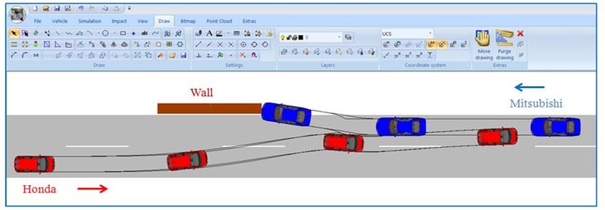
World Journal of Advanced Engineering Technology and Sciences, 2021, 02(01), 082–090
Figure 5 Road crash scene with multiple collisions.
Figure 6 shows the variation of the speeds of the two cars, as well as some parameters related to the collision between
them, which is the primary impact of the road accident in the case without a post-impact control system. The speeds of
the cars in the initial position were vi1=65 km/h at Honda and vi2=45 km/h at Mitsubishi. It also results that the impact
between cars was at t =1.82 s, at which the impact speeds were v1=46.6 km/h and v2 =29.2 km/h.
Figure 6 Travel speeds of the two cars and some impact parameters.
At this first impact (shown in figure 7) the separation speeds are V1=35.1 km/h and V2=22.3 km/h, values presented
in the impact diagram. Figure 6 also shows that following the impact between cars, their maximum deformations (on
the main direction of force) were x1=18 cm and x2=15 cm, respectively. The deformation energies were Ed1 = 30.68 kJ
and Ed2 = 26.96 kJ, respectively. Delta-V, which indicates the severity of the impact, were V1=14.96 km/h and
V2=10.37 km / h. The restitution coefficient is ε= 0.15, and the tangential friction coefficient μ=0.55.
87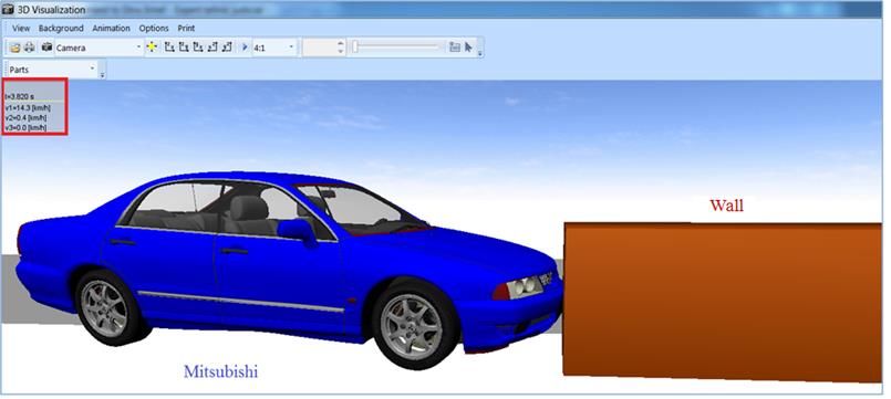
World Journal of Advanced Engineering Technology and Sciences, 2021, 02(01), 082–090
Figure 7 The first impact of the accident, between the two cars.
Figure 6 also shows the secondary impact at time t =3.82 s shown in Figure 8, when the Mitsubushi car hit the wall at a
speed of 4.2 km/h and stopped.
Figure 8 The second impact of the accident, between the Mitsubishi car and the wall.
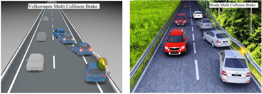
It is still considered that the Mitsubishi car has a post-impact control system with solution 1 previously shown, so with
the possibility of avoiding the impact with the wall by an additional braking (MCB system: Multi-Collision Brake).
The graph in figure 9 is thus obtained with the speeds for this case, from which the absence of the secondary collision
with the wall is ascertained, the Mitsubishi car stopping in front of it at time t =4.08 s, aspect confirmed also in detail A.
The stopping of the Mitsubishi car in front of the wall is also confirmed in figure 10, where it is found that the car stopped
at a distance of 0.54 m from the wall at time t =4.08 s; in figure 10a there is a representation in the plane, and in figure
10b a representation in space.
88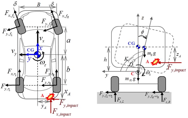
World Journal of Advanced Engineering Technology and Sciences, 2021, 02(01), 082–090

         Figure 9 Travel speeds of cars in the situation of being equipped with a post-impact control system.

                 Figure 10 Avoid collisions with the wall by additional braking after the first impact.

5. Conclusion
The post-impact dynamics control system is of great importance, as an impermissible deviation of the trajectory after a
first impact can lead to road accidents with serious consequences for people and significant damage to the vehicles
involved. For this reason, the control and stability of the post-impact dynamics concern aspects related to the vehicle,
the road and the driver.

Of the four possible solutions to be used by the post-impact control system, the most widely used is to avoid further
collisions by additional braking. Of all four solutions, the rapid response of the post-impact control system is of major
importance.

                                                                                                                      89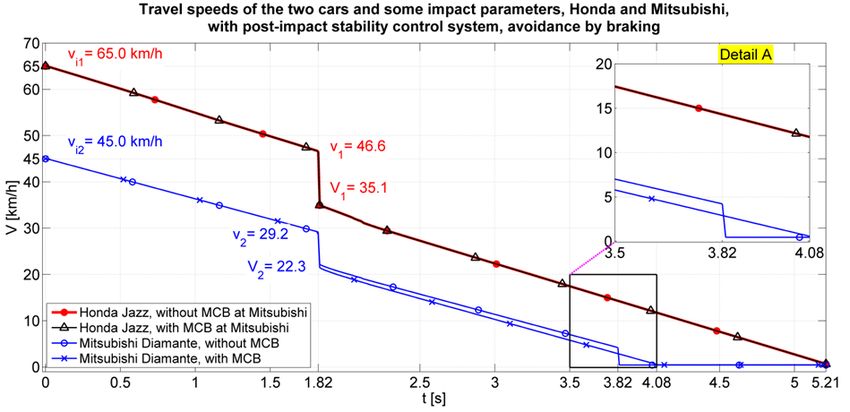
World Journal of Advanced Engineering Technology and Sciences, 2021, 02(01), 082–090

References
[1]    Brach R, Brach M. Vehicle accident analysis and reconstruction methods. SAE,Varrendale, USA, 2011stone M. Car-
       following, a historical review. University of Southampton. 2000
[2]    Datentechnik S. PC-Crash. Operating and technical manual. Mea forensic, USA. 2013.
[3]    Derong Y. Vehicle Dynamics Control after Impacts in Multiple-Event Accidents. Chalmers University of
       Technology. 2013.
[4]    Gao Y. Development and Integration of a Post Impact Control function for Passenger Vehicles. PhD thesis,
       Chalmers University of Technology. 2014.
[5]    Guoye W. Study of ESP control. International Conference of SSDMS. 2012.
[6]    Kim B, Yao M. Optimal Vehicle Motion Control to Mitigate Secondary Crash after an Initial Impact. PhD thesis,
       University of Michigan. 2015.
[7]    Mane SE. Detection and Prevention of Accidents using IOT, International Journal for Research in Applied Science
       & Engineering Technology (IJRASET), Volume 8, Issue XI, Nov 2020; 630-634.
[8]    Sokolovskij E. Modelling of collisions of the automobiles. Technical University, Vilnius. 2006.
[9]    Soltani A. Low cost integration of EPAS and ESP. PhD thesis, Cranfield University. 2014.
[10]   Uchenna Christopher Akwara. The rigid kinetic energy (RKE) concept for deflective suspended mobile robot in
       energy workspace. World Journal of Advanced Engineering Technology and Sciences, (WJAETS). 2021; 02(01):
       001–010.
[11]   Wach W. Simulation of vehicle accidents using PC-Crash. Institute of forensic Research Publishers, Cracow,
       Poland. 2011.
[12]   Yang D. Vehicle Dynamics Control after impacts in multiple-event accidents. PhD thesis, Chalmers University o
       Technology. 2013.
[13]   Ilie V, Fratila Gh, Stoica R-M, Nicolau M, Pantece I. Aspects regarding the rollover crash reconstruction of road
       accidents. Asian Academic Research Journal of Multidisciplinary. august 2017; 4(8): 37-47.
[14]   Stoica R-M, Radulescu V-J, Neagu D, Trocan C, Copae I. Aspects Regarding the Analysis and Reconstruction of Car
       Crashes. ROJAE. september 2017; 23: 113.
[15]   Voicu D, Barothi L, Stoica R-M, Mandache-Dodoiu A. The Development of a Recording System Able to Read Vehicle
       Parameters From On-Board Computer Without the Use of a Dedicated/Universal Tester. The International
       Congress off Automotive and Transport Engineering, AMMA 2018.

                                                                                                                     90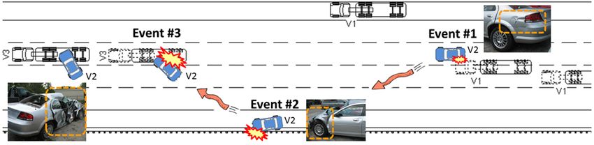
You can also read