Review of AT&T Small Cell Wireless Applications - Prepared for the City of Burlingame January 2019 - Burlingame.org
←
→
Page content transcription
If your browser does not render page correctly, please read the page content below
Review of AT&T Small Cell Wireless
                     Applications
        Prepared for the City of Burlingame
                               January 2019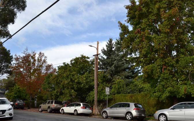
Review of Small Cell Wireless Application – AT&T Burlingame, CA | January 2019

Contents
1     Executive Summary ...................................................................................................................................... 1

    1.1   Overview of Analysis........................................................................................................................................1

    1.2   Findings ...........................................................................................................................................................2

2     Brief Background on Cellular Antenna Issues ................................................................................................ 3

    2.1   Wireless Coverage and Target Signal Levels ...................................................................................................3

    2.2   FCC Guidelines for Human Exposure to Radio Frequency Fields ......................................................................3

3     Overview of Current and Planned AT&T Service in the City .......................................................................... 6

    3.1   AT&T’s Stated Intent for New Sites .................................................................................................................6

    3.2   On-Site Field Tests ...........................................................................................................................................6

4     Summary of the Small Cell Applications........................................................................................................ 8

    4.1   Summary of Small Cell Application for Site 1800 Hillside Drive .......................................................................8

    4.2   Summary of Small Cell Application for Site 701 Winchester Drive ................................................................12

    4.3   Summary of Small Cell Application for Site 704 Winchester Drive ................................................................15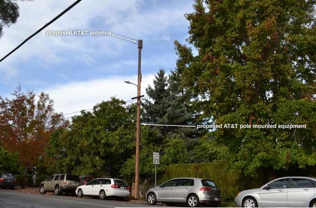
Review of Small Cell Wireless Application – AT&T Burlingame, CA | January 2019

Tables
Table 1: AT&T Capacity by Wireless Band .....................................................................................................................6
Table 2: Data Transmission Test Measurements at 1800 Hillside Drive ........................................................................7
Table 3: Data Transmission Test Measurements at 701 Winchester Drive ...................................................................7
Table 4: Communications Equipment Specifications - Site 1800 Hillside ....................................................................10
Table 5: Communications Equipment Specifications - Site 701 Winchester ...............................................................13
Table 6: Communications Equipment Specifications - Site 704 Winchester ...............................................................17

Figures

Figure 1: FCC Limits for Maximum Permissible Exposure ..............................................................................................4
Figure 2: Most Critical Areas for Consideration of RF Exposure ....................................................................................5
Figure 3: Drive Test Results for Burlingame ..................................................................................................................7
Figure 4: Site 1800 Hillside Drive Existing Photo ...........................................................................................................8
Figure 5: Site 1800 Hillside Drive Photo Simulation ......................................................................................................9
Figure 6: Site 1800 Hillside Drive Antenna Radiation Pattern .....................................................................................11
Figure 7: Site 701 Winchester Drive Existing Photo.....................................................................................................12
Figure 8: Site 701 Winchester Drive Photo Simulation................................................................................................13
Figure 9: Site 701 Winchester Drive Antenna Radiation Pattern ................................................................................14
Figure 10: Site 704 Winchester Drive Existing Photo...................................................................................................15
Figure 11: Site 704 Winchester Drive Photo Simulation (Source: AT&T) ....................................................................16
Review of Small Cell Wireless Application – City of Burlingame, CA | January 2019

1 Executive Summary
The City received two applications (including one alternative site location) from AT&T to mount
wireless access facilities on existing utility poles. The small cell wireless facility siting applications
are designed to serve targeted coverage gaps where there is currently either low RF signal level
or inadequate network throughput capacity. A small cell typically provides network coverage
within 1,000 to 1,500 feet from the site.

Columbia Telecommunications Corporation (CTC) is an independent telecommunications
consulting firm that has been retained by the City to perform a technical review of the
applications. CTC has performed a technical review and analysis of the applications with respect
to AT&T’s communications engineering materials, its justification for the sites, and the overall
functionality of this site in relation to other existing and proposed AT&T transmission facilities.

This report describes the information that we received and documents our analysis and
conclusions related to the applications. Our analysis does not include a review or evaluation of
the appropriateness of the proposed facilities or sites. Rather, our analysis is confined to the
technical aspects of the applications and includes:

    1. A review of the technical equipment that is being proposed by the applications and the
       suitability of such equipment to meet the purposes set forth by the applications

    2. A review of the RF emissions studies submitted by the applicant to confirm that the
       proposal would not exceed the Federal Communications Commission (FCC) RF emissions
       guidelines

    3. An evaluation of the coverage and network maps submitted by the applicant to determine
       whether such existing and potential coverage can be confirmed

    4. An evaluation of technically feasible alternative locations and equipment design
       configurations that would meet the purposes set forth by the applications

Accordingly, our recommendation is based on an evaluation of the technical characteristics of
the proposal being made and does not intend to address the traffic, public safety, or various
other potential impacts of the proposal upon the surrounding area, the public, or the City as a
whole.

1.1 Overview of Analysis
This report documents CTC’s findings relative to AT&T’s proposed sites. In November 2018, CTC’s
engineers performed the following tasks:

                                                                                                        1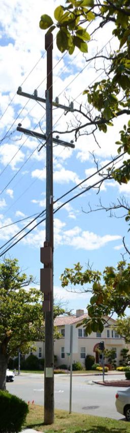
Review of Small Cell Wireless Application – City of Burlingame, CA | January 2019

    •   Reviewed all application materials submitted by AT&T, including:
            o Coverage maps (showing the target area and vicinity)
            o Equipment specifications
            o RF level analysis
            o Photo simulations
    •   Conducted a site visit to inspect the proposed locations and vicinity, and to verify the
        documentation provided in the applications
    •   Conducted on-site coverage and capacity tests at and near the proposed locations
    •   Conducted an independent review of the applications for compliance with FCC guidelines
        on Human Exposure to Radio Frequency Electromagnetic Fields
    •   Examined the area around the proposed sites to seek to identify suitable alternative
        locations
    •   Identified potential site design changes that may enhance the aesthetics of the
        infrastructure in the City’s judgment

1.2 Findings
We recommend these applications from a technical standpoint. In summary:

    •   Our review of the proposed technical equipment finds that the equipment is suitable to
        meet the purposes set forth by the applications.

    •   Our review of the RF emissions studies submitted by the applicant (prepared by the
        engineering consulting firm of Hammett & Edison) and the independent analysis of our
        team (under the supervision of Lee Afflerbach, P.E.) confirm that at each site, the total
        calculated RF emissions would not exceed the FCC’s guidelines at ground level or at the
        antenna’s horizontal planes.

    •   Our on-site testing of AT&T’s current network performance at the two sites found that
        most of AT&T’s network delivers wireless throughout area examined, but data transfer
        rates vary greatly. In most cases, our measurements recorded wireless signal levels of
        sufficient amplitude to support the high-speed transfer of data—but user demand had a
        clear effect on network throughput.

                                                                                               2
Review of Small Cell Wireless Application – City of Burlingame, CA | January 2019

2 Brief Background on Cellular Antenna Issues
The following brief discussion presents a framework for understanding our analysis of AT&T’s
application and our findings.

2.1 Wireless Coverage and Target Signal Levels
Wireless coverage for modern 4G technology broadband services is determined by a carrier’s
radio frequency (RF) signal amplitude and signal quality within a desired service area. Signals
need to be at a minimum amplitude to override noise and, in many cases, interference from other
wireless facilities. Signal levels also need to be maintained at a power level such that user devices
are not constantly connecting and reconnecting (either because of a loss of signal or because an
existing connection is overpowered by another wireless access point).

Handing off a user from one access site to another is part of the mechanics of dealing with users
who are in motion—particularly in an urbanized area with multiple signal paths and tower sites.
Further, modern 4G technologies as employed by AT&T and other carriers operate with
sophisticated encoding technology that permits higher transmission speeds in areas where signal
levels are higher than those required for minimum data rate transfers.

While the Federal Communications Commission (FCC) has no technical standards for the services
provided by commercial wireless carriers, the industry and equipment manufacturers have
generally established target signal levels for various service environments. Typically referenced
service environments include outdoor coverage, in-vehicle coverage, and in-building coverage.

For 4G technology, target levels are specified in terms of the ratio of decibels (dB) to milliwatts
(mW) of signal power, with a reference level of 0 dBm being equal to 1 milliwatt of signal power.
Modern cellular equipment is extremely sensitive and can operate at signal levels as low as -120
dBm RSRP. 1

2.2 FCC Guidelines for Human Exposure to Radio Frequency Fields
The FCC’s guidelines for evaluating human exposure to RF signals were first established in 1985.
The current guidelines were adopted in August 1997 in FCC OET Bulletin 65. 2 The guidelines are
expressed in terms of Maximum Permissible Exposure (MPE) to electric and magnetic field
strength and power density. The guidelines cover the frequency range of 300 kHz to 100 GHz.
The guidelines cover two separate tiers of exposure:

    1. Occupational/controlled exposure limits apply to situations in which persons are exposed
       as a consequence of their employment and in which those persons who are exposed have

1
 Reference Signals Received Power, measured in dBm, indicates the power of an LTE cellular signal.
2
 “Evaluating Compliance with FCC Guidelines for Human Exposure to Radiofrequency Electromagnetic Fields,” OET
Bulletin 65, edition 97-01. https://www.fcc.gov/general/oet-bulletins-line#65

                                                                                                           3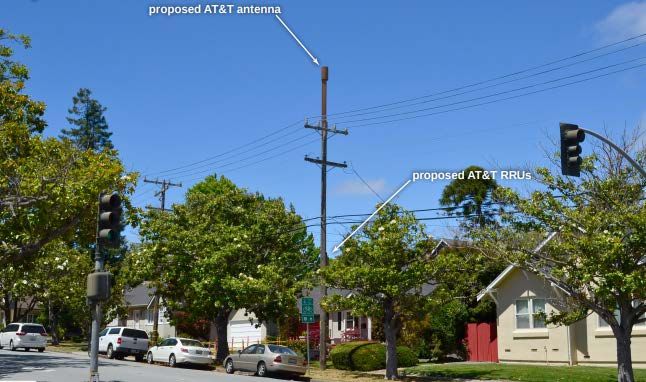
Review of Small Cell Wireless Application – City of Burlingame, CA | January 2019

        been made fully aware of the potential for exposure and can exercise control over their
        exposure.

    2. General population/uncontrolled exposure limits apply to situations in which the general
       public may be exposed or in which persons who are exposed as a consequence of their
       employment may not be made fully aware of the potential for exposure or cannot
       exercise control over their exposure.

Figure 1 is a plot of MPE as a function of RF.

                     Figure 1: FCC Limits for Maximum Permissible Exposure (mW/cm2)

Figure 2 illustrates the areas where the greatest RF exposure is present—specifically, at or near
the base of the antenna mounting structure and horizontally at an elevated location near the
antenna.

                                                                                               4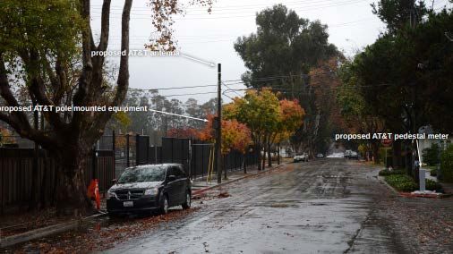
Review of Small Cell Wireless Application – City of Burlingame, CA | January 2019

                       Figure 2: Most Critical Areas for Consideration of RF Exposure

                                                         Area where an occupied
                                                         structure might be adjacent to
                                                         the antenna

                                                           Area where a pedestrian
                                                           might be near the pole’s
                                                           base

                                                                                          5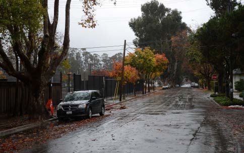
Review of Small Cell Wireless Application – City of Burlingame, CA | January 2019

3 Overview of Current and Planned AT&T Service in the City
AT&T currently provides commercial wireless service throughout the City with antennas
mounted on buildings and towers. These traditional wireless facilities, which are designed to
serve users in a 1- to 2-mile radius, are often referred to as “macro” sites.

AT&T delivers service in three wireless bands (Table 1). Historically, wireless service providers
used different bands for different services (voice/data/text), now all wireless services are
transmitted without regard to the kind of end-user activity across all wireless bands. However,
while AT&T’s existing sites cover the City, most areas of the City receive only 700 MHz service.
Coverage in the higher-frequency PCS and AWS bands—which account for 75 percent or more of
AT&T’s total bandwidth—are limited to areas within one-half mile or less from the macro sites.

                                 Table 1: AT&T Capacity by Wireless Band

                 Band             Licensed FCC Spectrum Service            Frequency
                 700 MHz         UHF low band                               700 MHz
                 PCS             Personal Communications Service           1,900 MHz
                 AWS             Advanced Wireless Service                 2,100 MHz

3.1 AT&T’s Stated Intent for New Sites
AT&T’s proposed “small cell” antenna node sites are intended to enhance the performance of
AT&T’s Long-Term Evolution (LTE) service. LTE is the standard behind today’s top-of-the-line 4G
(fourth-generation wireless) smartphones and tablets. (We note, too, that future 5G deployment
is expected to build upon ongoing upgrades of existing 4G infrastructure.)

The proposed small cells, placed at targeted locations, would provide additional capacity and
increased signal strength to serve users in areas that do not currently have access to AT&T PCS
and AWS signal coverage. The small cells would also reduce the net load on the macro sites.

3.2 On-Site Field Tests
Our signal intensity measurements confirm that AT&T’s existing network delivers a signal level
that is mostly adequate to support a high level of connectivity and service (i.e., the network
provides adequate coverage).

This finding matches our experience in other communities in California where AT&T LTE sites that
are not subjected to the demands of a large concurrent user base (i.e., user demand does not
overwhelm the network’s capacity) consistently deliver reliable download speeds in the range of
30 Mbps to 40 Mbps and upload speeds ranging from 10 Mbps to 25 Mbps (i.e., performance
typically achievable with the current generation of 4G LTE transmission equipment).

That said, the data transmission rates we measured performed far below those at the two sites
at the time of our sampling. For example (in Table 2), our measurements at 1800 Hillside Drive

                                                                                               6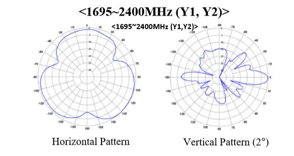
Review of Small Cell Wireless Application – City of Burlingame, CA | January 2019
were extremely poor with 1990’s-era dial-up upload speeds and very high latency times (the time
it takes to connect to the server which is conducting the speed tests). At 701 Winchester Drive
(Table 3), both download and upload speeds are more acceptable, along with good latency times
show, although the lower download speeds still indicate a heavily loaded network with many
concurrent users.
Table 2: Data Transmission Test Measurements at 1800 Hillside Drive
Table 3: Data Transmission Test Measurements at 701 Winchester Drive
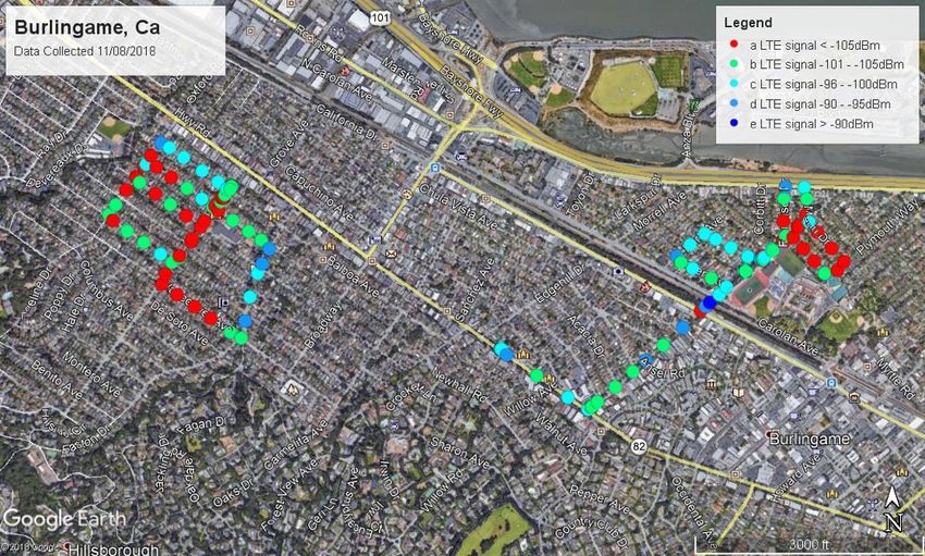
In addition to the on-site speed tests, we conducted drive test measurements of signal levels on
primary roads in and near the proposed small cell deployment areas. Figure 3 is a map illustrating
the signal levels recorded. During the day in which testing was conducted, we experienced no
disconnects and no interruption in the connection to the 4G LTE network service.
Figure 3: Drive Test Results for Burlingame
7Review of Small Cell Wireless Application – City of Burlingame, CA | January 2019
4 Summary of the Small Cell Applications
Burlingame applications comprise 3 individual sites.
• Site SFOK02_014 across from 1800 Hillside Drive
• Site SFOK02_019 adjacent to 701 Winchester Drive
• Site CRAN_RSFR_SFOK2_019 across from 704 Winchester Drive
We describe each site below.
4.1 Summary of Small Cell Application for Site 1800 Hillside Drive
The applicant proposes to install a wireless access facility on an existing 38′ 7″ utility pole across
from 1800 Hillside Drive that will be extended 7’0” in order to comply with the safety code for
clearance from power lines. The overall height of the extended pole will be 47′ 10″. Figure 4 is a
photograph of the existing pole.
Figure 4: Site 1800 Hillside Drive Existing Photo (Source: AT&T)
8Review of Small Cell Wireless Application – City of Burlingame, CA | January 2019
The site will be connected to the client network through a dedicated fiber optic communications
link. The link will monitor and control the site and will transport the communications traffic (i.e.,
voice and data) to and from the network users.
All equipment will be pole-mounted and fully visible. Figure 5 (below) is a photo simulation of
the site as it will look with the wireless equipment installed. The canister antenna will be mounted
on the top of the pole. The associated equipment to be mounted wholly on the pole includes two
LTE remote radios, coaxial cabling, antenna coupling devices, fiber network interface housing,
and a power disconnect switch.
Figure 5: Site 1800 Hillside Drive Photo Simulation (Source: AT&T)
AT&T’s application included specifications for the equipment that will be installed at the
proposed site (Table 4). This equipment is consistent with small cell hardware used throughout
the wireless industry.
9Review of Small Cell Wireless Application – City of Burlingame, CA | January 2019
Table 4: Communications Equipment Specifications - Site 1800 Hillside (Source: AT&T)
Item PCS (1900 MHz) AWS (2100 MHz)
KMW Shared Antenna Shared Antenna
Horizontal Beamwidth (°) 360 360
Bearing Azimuth (°) Omni Omni
Gain (dBd) 8.3 8.3
Vertical Beamwidth (°) 10.7 10.7
RAD Above Ground (feet) 46’-10” Shared Antenna
Dimensions (inches) 9.45” D x 23.63” H 9.45” D x 23.63” H
Coordinates 37.585211 /-122.37405 Shared Antenna
Ericson RRU-4415 RRU-4415
Power (Watts) 160 160
ERP (Watts) 683 683
Dimensions (inches) 14.96″ H x 13.19″ W x 7.39″ D 14.96″ H x 13.19″ W x 7.39″ D
AT&T submitted an independent engineering study of the level of RF emission exposure (both at
ground level and antenna height level) for the small cell equipment to be located at 1800 Hillside.
The study was prepared by the engineering consulting firm of Hammett & Edison, Inc., a firm that
specializes in RF emission analysis consistent with the guidelines established by the FCC. The
consultant calculated that the maximum ground-level RF exposure level due to the proposed
Verizon operation will be 0.0071 mW/cm², which is 0.7 percent of the applicable public exposure
limit. The consultant calculated that at antenna height level, the nearest end floor building is 30
feet away and will have an exposure level less than 1.8 percent of the MPE.
As part of our assignment we performed an independent analysis of the calculated RF exposure
levels at Site SFOK02-14. Figure 6 provides graphs of the RF energy emitted by the proposed
antenna in the horizontal and vertical planes. Note that in the horizontal plane, the radiation
pattern is essentially omni-directional with minor nodes due to the various fabrication
components. In the vertical plane, the maximum radiation is focused outward, perpendicular to
the utility pole. In the downward direction (toward the ground at the pole) the radiation is at
least 16 dB (1/40th) below the radiation in the horizontal plane.
10Review of Small Cell Wireless Application – City of Burlingame, CA | January 2019
Figure 6: Site 1800 Hillside Drive Antenna Radiation Pattern
Horizontal Radiation Pattern Vertical Radiation Pattern
Based on the specifications of the proposed antenna and transmission equipment, we concur
with the applicant’s findings that the maximum general-population RF exposure calculated for
the site at both the base and at the antenna’s horizontal plane is within the FCC’s MPE.
11Review of Small Cell Wireless Application – City of Burlingame, CA | January 2019
4.2 Summary of Small Cell Application for Site 701 Winchester Drive
The applicant proposes to install a wireless access facility on an existing 29′ 1″ utility pole adjacent
to 701 Winchester Drive that will be extended 7’0” in order to comply with the safety code for
clearance from power lines. The overall height of the extended pole will be 38′ 1″. Figure 7 is a
photograph of the existing pole.
Figure 7: Site 701 Winchester Drive Existing Photo (Source: AT&T)
The site will be connected to the client network through a dedicated fiber optic communications
link. The link will monitor and control the site and will transport the communications traffic (i.e.,
voice and data) to and from the network users.
All equipment will be pole-mounted and fully visible. Figure 8 (below) is a photo simulation of
the site as it will look with the wireless equipment installed. The canister antenna will be mounted
on the top of the pole. The associated equipment to be mounted wholly on the pole includes two
LTE remote radios, coaxial cabling, antenna coupling devices, fiber network interface housing,
and a power disconnect switch.
12Review of Small Cell Wireless Application – City of Burlingame, CA | January 2019
Figure 8: Site 701 Winchester Drive Photo Simulation (Source: AT&T)
AT&T’s application included specifications for the equipment that will be installed at the
proposed site (Table 5). This equipment is consistent with small cell hardware used throughout
the wireless industry.
Table 5: Communications Equipment Specifications - Site 701 Winchester (Source: AT&T)
Item PCS (1900 MHz) AWS (2100 MHz)
KMW Shared Antenna Shared Antenna
Horizontal Beamwidth (°) 360 360
Bearing Azimuth (°) Omni Omni
Gain (dBd) 8.3 8.3
Vertical Beamwidth (°) 10.7 10.7
RAD Above Ground (feet) 37’ Shared Antenna
Dimensions (inches) 9.45” D x 23.63” H 9.45” D x 23.63” H
Coordinates 37.58438056/-122.3482194 Shared Antenna
Ericson RRU-4415 RRU-4415
Power (Watts) 160 160
ERP (Watts) 683 683
Dimensions (inches) 14.96″ H x 13.19″ W x 7.39″ D 14.96″ H x 13.19″ W x 7.39″ D
13Review of Small Cell Wireless Application – City of Burlingame, CA | January 2019
AT&T submitted an independent engineering study of the level of RF emission exposure (both at
ground level and antenna height level) for the small cell equipment to be located at Site 701
Winchester Drive. The study was prepared by the engineering consulting firm of Hammett &
Edison, Inc., a firm that specializes in RF emission analysis consistent with the guidelines
established by the FCC. The consultant calculated that the maximum ground-level RF exposure
level due to the proposed AT&T operation will be .011 mW/cm², which is 1.1 percent of the
applicable public exposure limit. The consultant calculated that at antenna height level, the
nearest end floor building is 30 feet away and will have an exposure level less than 2.2 percent
of the MPE.
As part of our assignment we performed an independent analysis of the calculated RF exposure
levels at Site 701 Winchester Drive. Figure 9 provides graphs of the RF energy emitted by the
proposed antenna in the horizontal and vertical planes. Note that in the horizontal plane, the
radiation pattern is essentially omni-directional with minor nodes due to the various fabrication
components. In the vertical plane, the maximum radiation is focused outward, perpendicular to
the utility pole. In the downward direction (toward the ground at the pole) the radiation is at
least 16 dB (1/40th) below the radiation in the horizontal plane.
Figure 9: Site 701 Winchester Drive Antenna Radiation Pattern
Horizontal Radiation Pattern Vertical Radiation Pattern
14Review of Small Cell Wireless Application – City of Burlingame, CA | January 2019
Based on the specifications of the proposed antenna and transmission equipment, we concur
with the applicant’s findings that the maximum general-population RF exposure calculated for
the site at both the base and at the antenna’s horizontal plane is within the FCC’s MPE.
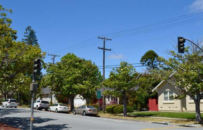
4.3 Summary of Small Cell Application for Site 704 Winchester Drive
The applicant proposes to install a wireless access facility on a replacement 24′ 11″ utility pole
across from 704 Winchester Drive. This site would be considered as an alternate site location for
the site near 701 Winchester Drive and only one of these sites would be required to be built to
accommodate AT&T’s network design. The overall height of the extended pole will be 27′ 3″.
Figure 10 is a photograph of the existing pole.
Figure 10: Site 704 Winchester Drive Existing Photo (Source: AT&T)
The site will be connected to the client network through a dedicated fiber optic communications
link. The link will monitor and control the site and will transport the communications traffic (i.e.,
voice and data) to and from the network users.
All equipment will be pole-mounted and fully visible. Figure 11 (below) is a photo simulation of
the site as it will look with the wireless equipment installed. The canister antenna will be mounted
on the top of the pole. The associated equipment to be mounted wholly on the pole includes two
LTE remote radios, coaxial cabling, antenna coupling devices, fiber network interface housing,
and a power disconnect switch. Since the original pole (and its proposed replacement) are owned
15Review of Small Cell Wireless Application – City of Burlingame, CA | January 2019
by AT&T, PG&E will not locate a power meter on the pole. Therefore, AT&T is proposing building
a pedestal meter across the street in a separate cabinet (4’2” high) across the street.
Figure 11: Site 704 Winchester Drive Photo Simulation (Source: AT&T)
AT&T’s application included specifications for the equipment that will be installed at the
proposed site (Table 6). This equipment is consistent with small cell hardware used throughout
the wireless industry.
16Review of Small Cell Wireless Application – City of Burlingame, CA | January 2019
Table 6: Communications Equipment Specifications - Site 704 Winchester (Source: AT&T)
Item PCS (1900 MHz) AWS (2100 MHz)
Commscope VVSSP-360S-F Shared Antenna
Horizontal Beamwidth (°) 360 360
Bearing Azimuth (°) Omni Omni
Gain (dBd) 6.6 7.3
Vertical Beamwidth (°) 21.9 19.1
RAD Above Ground (feet) 26’3” Shared Antenna
Dimensions (inches) 7.9” D x 23.6” H Shared Antenna
Coordinates 37.584718/-122.347514 Shared Antenna
Ericson RRU-4415 RRU-4426
Power (Watts) 160 160
ERP (Watts) 683 683
Dimensions (inches) 16.54″ H x 13.46″ W x 5.87″ D 14.96″ H x 13.19″ W x 7.39″ D
AT&T did not submit an independent engineering study of the level of RF emission exposure for
the small cell equipment to be located at Site 704 Winchester Drive. If a study is provided, we
can further review that information for compliance with FCC RF emissions requirements.
However, based on the specifications of the proposed antenna and transmission equipment and
its proximity to the originally proposed site near 701 Winchester Drive and nearby buildings, we
expect to find that the maximum general-population RF exposure calculated for the site at both
the base and at the antenna’s horizontal plane is within the FCC’s MPE.
17You can also read