Determining the Angle-of-Arrival of an Radio-Frequency Source with a Rydberg Atom-Based Sensora
←
→
Page content transcription
If your browser does not render page correctly, please read the page content below
Determining the Angle-of-Arrival of an Radio-Frequency Source with a
                                                   Rydberg Atom-Based Sensora)
                                                             Amy K. Robinson,1 Nikunjkumar Prajapati,1 Damir Senic,2 Matthew T. Simons,3 and Christopher L. Holloway3, b)
                                                             1)
                                                                Depart. of Electr. Engin., University of Colorado, Boulder, CO 80305, USA
                                                             2)
                                                                ANSYS, Inc., Boulder, CO, USA
                                                             3)
                                                                National Institute of Standards and Technology, Boulder, CO 80305, USA
                                                             (Dated: 29 January 2021)
                                                             In this work, we demonstrate the use of a Rydberg atom-based sensor for determining the angle-of-arrival of an
                                                             incident radio-frequency (RF) wave or signal. The technique uses electromagnetically induced transparency
                                                             in Rydberg atomic vapor in conjunction with a heterodyne Rydberg atom-based mixer. The Rydberg atom
arXiv:2101.12071v1 [physics.atom-ph] 28 Jan 2021

                                                             mixer measures the phase of the incident RF wave at two different locations inside an atomic vapor cell.
                                                             The phase difference at these two locations is related to the direction of arrival of the incident RF wave.
                                                             To demonstrate this approach, we measure phase differences of an incident 19.18 GHz wave at two locations
                                                             inside a vapor cell filled with cesium atoms for various incident angles. Comparisons of these measurements to
                                                             both full-wave simulation and to a plane-wave theoretical model show that these atom-based sub-wavelength
                                                             phase measurements can be used to determine the angle-of-arrival of an RF field.

                                                      The ability to measure angle-of-arrival (AoA) is of             laser (called a “coupling” laser) is used to establish a co-
                                                   great importance to radar and advanced communications              herence in the atomic system. When the RF E-field is
                                                   applications. Here we present a method of determin-                applied, it alters the susceptibility of the atomic vapor
                                                   ing AoA based on Rydberg-atom sensors. Atom-based                  seen by the probe laser. By detecting the power in the
                                                   sensors have garnered a lot of attention in the past sev-          probe laser propagating through the cell, the RF E-field
                                                   eral years because of their many possible advantages over          strength can be determined. This approach has shown to
                                                   other conventional technologies. Measurement standards             be very successful for determining the magnitude of an
                                                   have evolved towards atom-based measurements over the              RF E-field. However, an alternative approach is required
                                                   last couple decades; most notably length (m), frequency            to measure phase, which is necessary to determine AoA.
                                                   (Hz), and time (s) standards. Recently there has been              Recently, we developed a heterodyne technique using a
                                                   a great interest in extending this to magnetic and elec-           Rydberg atom-based mixer21 . In this approach, a ref-
                                                   tric (E) field sensors. In particular, since the initiation        erence RF field is applied to the atoms. This reference
                                                   and completion of DARPA’s QuASAR program, NIST                     RF field is on-resonance with the Rydberg-atom transi-
                                                   and other groups have made great progress in the devel-            tion, and acts as a local oscillator (LO). The LO field
                                                   opment of Rydberg atom-based radio-frequency (RF) E-               causes the EIT/AT effect in the Rydberg atoms which
                                                   field sensors1–12 . The Rydberg atom-based sensors now             is used to down-convert a second, co-polarized RF field
                                                   have the capability of measuring amplitude, polariza-              (referred to as SIG and is the field for which the phase is
                                                   tion, and phase of the RF field. As such, various ap-              desired). The SIG field is detuned (by a few kHz) from
                                                   plications are beginning to emerge. These include SI-              the LO field. The frequency difference between the LO
                                                   traceable E-field probes3,4 , power-sensors13 , receivers for      and the SIG is an intermediate frequency (IF) and the
                                                   communication signals (AM/FM modulated and digital                 IF is detected by optically probing the Rydberg atoms.
                                                   phase modulation signals)14–19 , and even recording mu-            This IF is essentially the beat-note between the LO and
                                                   sical instruments20 . In this paper, we investigate the ca-        SIG frequencies. The phase of the IF signal corresponds
                                                   pability of a Rydberg atom-based sensor for determining            directly to the relative phase between the LO and SIG
                                                   AoA of an incident RF field.                                       signals. In effect, the atoms down-convert the SIG to the
                                                      The majority of the work on Rydberg atom-based                  IF, and the phase of SIG is obtained by the probe laser
                                                   E-field sensors uses on-resonant electromagnetically in-           propagating through the atomic vapor.
                                                   duced transparency (EIT) and Autler-Townes (AT) split-                In order to determine the AoA, the phase (φ) of SIG
                                                   ting techniques4–6 . The concept uses a vapor of alkali            is needed at two different locations, see Fig. 1. Once the
                                                   atoms placed in a glass cell (referred to as a “vapor cell”)       phase of SIG is determined at the two different locations,
                                                   as a means of detecting and receiving the RF E-field or            the relationship between AoA (defined as θ in Fig. 1) and
                                                   signal. The EIT technique involves using two lasers. One           the phase difference at the two locations (location 1 and
                                                   laser (called a “probe” laser) is used to monitor the opti-        2 in the figure) can be calculated. Assuming SIG is a
                                                   cal response of the medium in the vapor cell and a second          plane wave, the relationship between θ and φ is:

                                                                                                                                                                −1   ∆φ2,1
                                                                                                                        ∆φ2,1 = φ2 − φ1 ≈ k d sin(θ) : θ ≈ sin                 (1)
                                                   a) Publication
                                                                                                                                                                       kd
                                                                  of the U.S. government, not subject to U.S. copy-
                                                   right.                                                             where d is the separation between the two locations, φ1,2
                                                   b) Electronic mail: christopher.holloway@nist.gov
                                                                                                                      are the phases of SIG at the two locations, k = 2π/λ,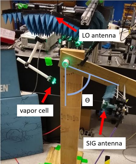
2

                                                                                    (a) Laser field schematic
FIG. 1. Incident plane wave (SIG) onto three locations sepa-
rated by d and offset by t.

and λ is the wavelength of SIG. This expression assumes
that the line formed by locations 1 and 2 is perpendicular
to the line for which the angle θ is measured. If the two
locations (say locations 1 and 3 in Fig. 1) form a line that
is not perpendicular to the line that determine θ, then
the phase difference between locations 1 and 3 are given
by

        ∆φ3,1 = φ3 − φ1
                 p
              ≈ k d2 + t2 sin θ + tan−1 (t/d)

                                                          (2)


                         ∆φ
        θ ≈ sin−1        √ 3,1          − tan−1 (t/d) ,   (3)                      (b) antenna arrangement
                        k d2 + t2
                                                                FIG. 2. (a) Schematic of the orientation of the optical fields.
where t is defined in Fig. 1. Eqs. (1)-(3) relate AoA to        The probe beam is split in two by a beam cube, and one cou-
the measured phase of the SIG and LO signals at two             pling field is re-circulated using a dichroic mirror to counter-
locations in the cell, assuming that the AoA is defined         propagate along each probe beam. (b) The LO antenna is sus-
in a plane orthogonal to the probe laser propagation.           pended above the cell, such that the LO field is incident nearly
                                                                perpendicular to the line between the two optical beams. The
Future work will include the measurement AoA in two
                                                                SIG is held by an adjustable arm to vary the angle of in-
dimensions, see discussion below.                               cidence, which is measured using an electronic compass at-
    To measure the phase at any two different locations,        tached to the horn mount.
we generate EIT in two locations inside a vapor cell
filled with 133 Cs, see Fig. 2(a). The probe laser is
split with a beam cube and passed through the vapor
                                                                approach3,4 ). A second SG is used to generate a CW
cell at two locations. The full power of the coupling
                                                                SIG field at 19.18 GHz+fIF (where the fIF =50 kHz)).
laser is passed through each of the two locations, see
                                                                The output from the two SG are connected to two stan-
Fig. 2(a). The beam directions are chosen to ensure
                                                                dard gain horn antennas via RF cables. The LO horn is
that at both locations in the cell, the probe and cou-
                                                                mounted directly above the vapor cell and is stationary,
pling lasers are counter-propagating. To generate EIT at
                                                                whereas the SIG horn sits on a rotating arm which sets
the two locations in the cell, we tune the probe laser to
                                                                the incident angle (θ).
the D2 transition for 133 Cs (6S1/2 -6P3/2 or wavelength of
λp = 852.35 nm) focused to a full-width at half maximum            Two different photodetectors are used to monitor the
(FWHM) of 390 µm, with a power of 96 µW. To pro-                two probe beams that travel through the vapor cell. The
duce an EIT signal, we couple to the 133 Cs 6P3/2 -58S1/2       output of the photodetectors are sent to an oscilloscope
states by applying a counter-propagating coupling laser         and a lock-in amplifier. Fig 3(a) shows the beam position
at λc = 509.26 nm with a power of 60 mW, focused to a           at the two locations inside the vapor cell. These beam
FWHM of 450 µm.                                                 positions correspond to locations 1 and 3 as defined in
    The LO and SIG are applied to the vapor cell as shown       Fig. 1, and the phase relationship is given in eq. (3). In
in Fig. 2(b), where the LO is at a fixed position and the       our experiments, d = 2.6 mm and t = 0.3 mm. The
SIG is rotated to different incident directions (θ). We         lock-in is referenced to a 50 kHz signal from a mixer that
use a signal generator (SG) to apply a continuous wave          is fed by the two signal generators. The Rydberg atoms
(CW) LO field at 19.18 GHz to couple states 58S1/2 and          automatically down-convert the CW carrier (i.e., SIG)
59P3/2 . While we use 19.18 GHz in these experiments,           to the IF (the amplitude of the probe laser transmission)
this approach can work at carriers from 100 MHz to              and the phase of SIG is determined.
1 THz (because of the broadband nature of the EIT/AT               The Rydberg-atom sensor and the photodetectors act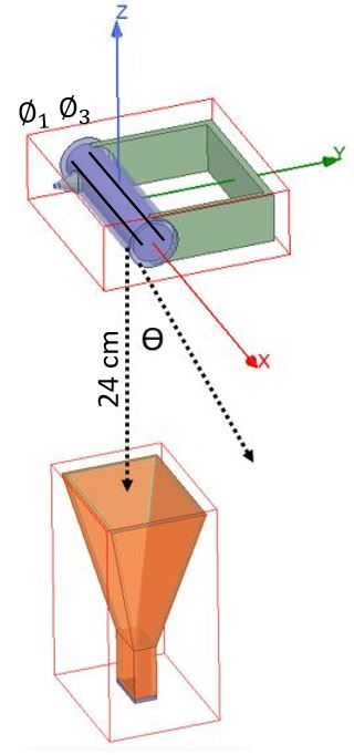
3
figure are the theoretical results given in eq. (3). Upon
comparing the experimental results to the theoretical re-
sults, we see that while the standard deviation for the
phase measurement for each incident angle is small (i.e.,
small error bars), the measurements do not lie exactly
on the theoretical results. The reason why the data does
not exactly follow the theoretical model is twofold. First,
from Fig. 2(b) we see there are several objects in the ap-
paratus used to rotate the SIG antenna. These objects
cause scattering which are not accounted for in the the-
(a) (b)
oretical results. The second reason is due to the vapor
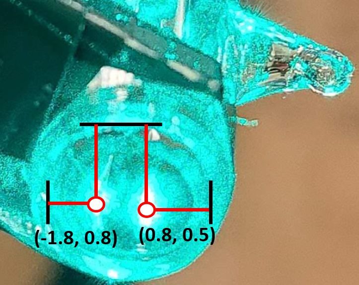
FIG. 3. (a)The x-y location of lasers inside vapor cell, where cell itself. Because the vapor cell is a dielectric, the RF
the origin is the center of the cell, and (b) Beat-note for two fields can exhibit multi-reflections inside the cell and RF
locations inside the vapor cell. standing waves (or resonances) in the field strength can
develop in the cell4,5,25,26 . Thus, for a given location in-
side the cell, the RF field can be larger or smaller than
like a mixer and low pass filter in a classic RF hetero- the incident field and the phase of the field at a given
dyne setup. The LO and SIG create a beat-note and the location will be perturbed as well. Hence, the stand-
atoms respond directly to this beat-note, which is de- ing wave can generates differences in the measured AoA
tected by the probe laser transmission measured on the when compared to the expected sinusoidal relationship
photodetectors. At each location inside the vapor cell, as given in eqs. (1) and (3). Numerical models can be
the total electric field (Eatoms ) is the sum of the LO and used to investigate this effect. While modeling the entire
SIG fields (ELO and ESIG ). The atoms demodulate the structure used to support the SIG antenna is difficult, we
high-frequency ωLO field and the probe transmission as can use full-wave numerical tools to simulate the vapor
a function of time at locations i and j (1 and 3 as defined cell effects.
in Fig. 1) is given by21,22
We use ANSYS HFSS (High Frequency Structure
T(i,j) ∝ |Eatoms | ≈ ELO + ESIG cos (∆ω t + φi,j ) , (4) Simulator)27 to simulate only the SIG antenna and the
vapor cell (including the plastic vapor-cell holder), see
where φi,j corresponds to the phase of SIG at locations Fig. 5. HFSS convergence criteria was based on the en-
i and j, and ∆ω = ωLO − ωSIG . Once φi and φj are ergy of a plane wave to 0.01 W, and the mesh around
determined from the probe laser transmissions measured the cell was seeded using curvilinear approximation, and
on the two different photodetectors, the phase difference inside the cell using length-restriction to 1 mm, with
(∆φ) between the two locations is given by first order polynomial solving. With this model, we de-
termine the phase at location 1 and 3 (as defined in
∆φ = φj − φi . (5) Fig. 1) and the ∆φ3,1 obtained from HFSS are shown
in Fig. 4(a). To ensure that the phases are being calcu-
To be more exact, φi,j is actually the phase difference lated correctly with the HFSS simulation, we first deter-
(at each location) between the LO and SIG21 . In these mine ∆φ3,1 with no vapor cell present. These results are
experiments, LO is at a fixed location such that a mea- shown in Fig. 4(a) and match the theoretical calculation
surement of ∆φ is a measurement of the phase change of closely, as expected. Now that we have confirmed that
SIG between the two locations. the HFSS is implemented correctly, the result from the
For a given incident angle θ, the beat-notes as mea- HFSS for the case when the vapor cell is included are
sured from the two photodetectors are shown in Fig. 3(b). shown in Fig. 4(a). We see that the HFSS results (in-
From the figure, we see the “cosine” behavior as predicted cluding the vapor cell) correspond well to the measured
by eq. (4) with a period of 20 µs (or the IF frequency of data for angles >-25o . As with the experimental results,
50 kHz used in the experiments). In this figure we see the HFSS results indicate that the vapor cell does per-
that the two beat-notes are shifted in phase. This is the turb the phase measurement and causes deviation from
phase difference for the given incident angles that is de- the theoretical results. We see that the HFSS results do
fined in eq. (3). not correspond exactly to the measured data over all the
Using the setup shown in Fig. 2(b), the SIG antenna angles, but do show the same trends. The deviations be-
is scanned from θ = ±40o . The phase difference (∆φ) tween the measured data and HFSS are twofold. First,
at each θ position was determined and the measured ∆φ the exact permittivity (r ) of the glass is not known, r
for each incident angle is shown in Fig. 4(a). The error ranges from 3 to 628 (in this numerical model we as-
bars correspond to the standard deviation of 5 data sets. sume r = 5). Secondly, upon comparing the photo of
The uncertainties of Rydberg atom based measurements the experimental setup in Fig. 2(b) and the HFSS model
in general are discussed in Ref.23 and it is shown in Ref.24 in Fig. 5, we see that not all the objects used to rotate
that the heterodyne Rydberg atom-based mixer approach the SIG antenna are included in the HFSS model. With
can measure the phase to within 1o . Also shown in this that said, the measured and HFSS model compare well4
measured ∆φ, the deviation in the measured AoA (and
the HFSS results for AoA) is due to the vapor cell per-
turbation and due to the supporting apparatus used to
experimental equipment (SIG antenna and vapor cell).
This demonstrates that the Rydberg atom-based sensor
can be used to determine AoA of an incident RF signal.
While the cell does perturb the AoA measurement,
two approaches can be pursued to mitigate this effect.
One approach is to design a vapor cell that can minimize
and even eliminate the vapor cell perturbations. Various
groups are investigating different approaches to modify
(a) (b)
the vapor cell used for these Rydberg atom-based sensors.
Two examples include the use of vapor cells with honey-
FIG. 4. (a) Experimental and HFSS data for ∆φ. The error
comb sides29 or the use of metamaterials on the sides of
bars correspond to the standard deviation of 5 data sets, and
(b) AoA from the experimental data.
the vapor cells30 . A second approach is to use the HFSS
results to calibrate the vapor cell to reduce the perturba-
tion effects. This is done by defining a calibration factor
as
C = AoAHF SS − AoAtheory (6)
and subtracting this from the measured AoA
AoAcal = AoAmeas − C (7)
where AoAHF SS , AoAtheory , and AoAmeas are the AoA
obtained from the HFSS results, theory, and experimen-
tal results, respectively. Fig. 4(b) shows AoAcal . While
there is not a perfect correlation to the solid line with
the calibration based on the HFSS results, we do see
that the calibration did improve the AoA measurement,
especially for angles >-25o . Once again, the deviations
FIG. 5. HFSS model for the cell and horn antenna. The from the theory and HFSS simulation for angles -25o . termine the angle of arrival of an RF signal using an
There are asymmetries in the apparatus use in the ex- atom-based sub-wavelength phase measurement method.
perimenters. For angles5
1 Gordon, J.A., et al., “Quantum-Based SI Traceable Electric- 21 Simons, M.T., et al., Applied Physics Letters, 114, 114101 2019.
Field Probe,” Proc of 2010 IEEE International Symposium on 22 Gordon, J.A., et al., AIP Advances, 9, 045030, 2019.
Electromagnetic Compatibility, July 25-30, 321-324, 2010. 23 Simons, M.T., et al., “Uncertainties in Rydberg atom-based RF
2 Sedlacek, J.A., et al., Nature Phys., 8, 819, 2012. E-field measurements,” in Proc. EMC Eur., Amsterdam, The
3 Holloway, C.L., et al., IEEE Trans. on Antenna and Propag., Netherlands, pp. 376–380, Aug. 2018.
62(12), 6169-6182, 2014. 24 Simons, M.T., et al., IEEE Access, vol. 7, pp. 164975-164985,
4 Holloway, C.L., et al., IEEE Trans. on Electromagnetic Compat., 2019, doi: 10.1109/ACCESS.2019.2949017.
59(2), 717-728, 2017. 25 Simons, M.T., et al., ”Applications with a Rydberg Atom-based
5 Holloway, C.L., et al., Applied Phys. Lett., 104, 244102-1-5, 2014. Radio Frequency Antenna/Receiver,” Procc in EMC EUrope
6 Sedlacek, J.A., et al., , Phys. Rev. Lett., 111, 063001, 2013. 2019, Barcelona, Spain, Sept. 2019.
7 Tanasittikosol, M., et al., J. Phys B, 44, 184020, 2011. 26 Fan H., et al., Physical Review Applied, 4, 044015, November,
8 Gordon, J.A., et al., Applied Physics Letters, 105, 024104, 2014. 2015.
9 Fan, H., et al., J. Phys. B: At. Mol. Opt. Phys., 48, 202001, 2015. 27 Ansys® HFSS, Release 2020R2,
10 Simons, M.T., et al., IEEE Access, 7, 164975-164985, 2019. https://www.ansys.com/products/electronics/ansys-hfss. Men-
11 Simons, M.T., et al., Applied Optics, 57(22), pp. 6456-6460, 2018. tioning this product does not imply an endorsement by NIST,
12 Anderson, D.A., et al. Physical Review Applied, 5, 034003, 2016. but serves to clarify the software used.
13 Holloway, C.L., et al., Applied Phys. Letters, 113, 094101, 2018.
28 Tropf, W.J., et al., Properties of Crystals and Glasses. Chapter
14 Song, Z., et al., Optics Express, 27(6), 2019. 33, p 33.7.
15 Meyer, D.H., et al., Appl. Phys. Lett., 12, 211108, 2018. 29 J.P. Shaffer, “Atom-based electromagnetic field sensing (Confer-
16 Holloway, C.L., et al., IEEE Antenna and Wireless Propag. Lett., ence Presentation),” Proc. SPIE 11296, Optical, Opto-Atomic,
18(9), 1853-1857, 2019. and Entanglement-Enhanced Precision Metrology II, 112960Q
17 Cox, K.C., et al., Phys. Rev. Lett. 121, 110502, 2018. (27 March 2020); https://doi.org/10.1117/12.2552626.
18 Holloway, C.L., et al., “A Multi-Band Rydberg-Atom Based Re- 30 H. Mu, et al., “A Low Permittivity Metamaterial on a Glass
ceiver: AM/FM Stereo Reception”, IEEE Antenna and Propa- Substrate for Fabricating an Atomic Vapor Cell,” 2019 Photon-
gation Magazine, 2020. ics & Electromagnetics Research Symposium - Fall (PIERS -
19 Anderson, D.A., et al., arXiv:1808.08589v1, Aug. 26, 2018. Fall), Xiamen, China, 2019, pp. 344-350, doi: 10.1109/PIERS-
20 Holloway, C.L., et al., AIP Advanced, 9(6), 065110, 2019. Fall48861.2019.9021792.You can also read