Design of Dual-Band Conformal AMC Integrated Antenna for SAR Reduction in WBAN
←
→
Page content transcription
If your browser does not render page correctly, please read the page content below
Progress In Electromagnetics Research C, Vol. 110, 91–102, 2021

 Design of Dual-Band Conformal AMC Integrated Antenna for SAR
                      Reduction in WBAN

                          Bidisha Hazarika, Banani Basu* , and Arnab Nandi

Abstract—A wearable, miniaturized, dual-band, Artificial Magnetic Conductor (AMC) integrated
antenna operating on ISM band (2.38–2.47 GHz) and WLAN band (5.11–5.31 GHz) is proposed for
Wireless Body Area Network (WBAN). A dumbbell shaped unit-cell is designed to achieve zero reflection
phase and modified material characteristics. When 2 × 2 array of dumbbell shaped AMC is put
underneath the monopole, the antenna gain increases up to 9.5 dB and 8.1 dB at 2.43 GHz and 5.2 GHz,
respectively. Different bending conditions have been considered to confirm the robustness of the AMC
antenna. Debye model is used to approximate the dielectric properties within phantom tissue model.
Antenna shields most of the backward radiation and reduces the specific absorption rate (SAR) of the
integrated antenna by more than 95% in 1-g of phantom hand tissues at both the frequencies. The
acquired results exhibit that the AMC antenna is more secure for on body applications.

1. INTRODUCTION

With the recent growth of WBAN system, it is crucial to design an antenna to be implanted inside and
outside the human body. Antennas used for wearable applications are essentially compact, light weight,
and mechanically robust. Use of AMC to achieve low profile, high gain, and unidirectional antenna
is studied in many articles [1–4]. Application of AMC to achieve improved radiation performance and
higher isolation in dual bands is reported in [1]. [2] presents an AMC loaded antenna resonating at
2.45/5.8 GHz to reduce the SAR. Article [3] has proposed a metamaterial based high gain antenna
for radar and BAN applications. A low-profile left-handed metamaterial based multiband antenna for
wireless application is proposed in [4]. Another high gain metamaterial antenna for long range radio
frequency identification (RFID) applications has been reported in [5]. In [6], an AMC planar antenna is
introduced with 43.3% SAR reduction. A low-profile antenna based on AMC is designed to lower SAR
value for WLAN application [7]. In [8], a wearable monopole in both flat and bent conditions has been
designed. A dual-band AMC antenna is presented to lessen SAR up to 70% [9]. A wearable antenna
with reduced SAR has been reported for indoor-outdoor positioning system [10]. [11] has introduced
a low SAR, dual-band wearable antenna to perform different structural deformation when it is placed
near artificial human body. Reduction of the SAR on different human body parts has become a topic
of recent interest for implantable and wearable antennas.
     The article presents a novel low-profile, conformal, dual-band AMC integrated antenna at 2.43 GHz
and 5.2 GHz. The AMC layer consists of a dumbbell-shaped unit-cell structure which possesses an
effective zero reflection phase at 2.5 GHz and bandwidth from 2.45 to 2.55 GHz limited within ±90◦
reflection phase. The reported AMC layer attains double-negative permittivity and permeability, and
negative refractive index in the designated bands. A monopole with rectangular slot covering 2.5 GHz
band is designed to integrate with AMC. The AMC integrated slotted monopole having 5 mm separation
   Received 12 December 2020, Accepted 9 February 2021, Scheduled 21 February 2021
* Corresponding author: Banani Basu (banani.basu@gmail.com).
The authors are with the Department of Electronics and Communication Engineering, National Institute of Technology Silchar,
Silchar, Cachar, Assam 788010, India.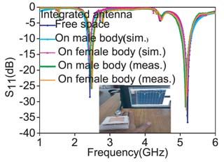
92                                                                            Hazarika, Basu, and Nandi

proffers dual operating bands and 9.5 dB and 8.1 dB gains at the respective bands. The integrated
antenna increases the front to back radiation to 6.3 dB and 21.2 dB at the two frequencies and has E-
field co-x pol intensity differences of 10.23 dB and 11.15 dB, and H-field intensity differences of 13.62 dB
and 12.21 dB at 2.43 GHz and 5.2 GHz, respectively. Excellent radiation efficiency values of 95% and
98.5% are achieved at both the bands. The AMC integrated antenna is deformed over different bending
radii to see the robustness of the antenna. Dielectric properties of the antenna are characterized at both
the bands when it is placed near human body. The AMC integrated antenna is placed on male and
female hand phantom models for 1-g tissues to see the maximum SAR performance. The values agree
well with that of the FCC and ICNIRP standards.

2. ANTENNA AND AMC DESIGN

Simulation is carried out to design AMC layer and a slotted monopole antenna for WBAN applications.
A dumbbell shaped AMC unit-cell is developed to be operated at 2.5 GHz. Different material
characteristics of the AMC layer have been studied to examine the double negative properties (ε < 0,
μ < 0).

2.1. Configuration of AMC
The proposed dumbbell shaped unit-cell is exhibited in Fig. 1(a). A Roger RO3003 flexible substrate
with εr = 3, tan δ = 0.0013, and thickness = 1.5 mm is used in the design. The AMC surface is
implemented by zero reflection phase characterization. It is seen from Fig. 1(b) that the exact point of
the zero phase reflection is positioned at 2.5 GHz with a small bandwidth from 2.45 GHz to 2.55 GHz
within ±90◦ phase values [12] where signal interference is obtained between the incident wave and
reflected wave. Master and slave boundaries and Floquet ports are used to establish the simulation for
infinite periodic array in HFSS.

                     (a)                             (b)                             (c)

Figure 1. (a) Design of unit-cell. (b) Design of 2 × 2 AMC and zero reflection phase of unit-cell. (c)
S-parameters of unit-cell.

2.2. Material Characteristics of Unit-Cell
The response of a design is determined through its permittivity (ε) and permeability (μ). Scattering
parameter-retrieval [12] is an effective method to extricate these material properties.                 The
characterization of the AMC requires a limitless number of unit-cells towards the lattice vectors
direction. These properties are attained by giving periodic boundaries to the unit-cell and the S-
parameters: S11 and S21 are extricated and presented in Fig. 1(c). ε and μ are extricated by utilizing
S11 and S21 , and shown in Figs. 2(a) and (b) correspondingly. In the figure it is proved that the designed
AMC offers small and negative ε and μ at the respective bands. It provides positive wave impedance
(z) and small negative index of refraction (n) which are eventually reflected in Figs. 2(c) and (d).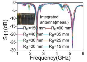
Progress In Electromagnetics Research C, Vol. 110, 2021                                         93

                                (a)                                    (b)

                                (c)                                    (d)

Figure 2. Material features of unit-cell. (a) Real μ, ε. (b) Imaginary μ, ε. (c) Real n, z and (d)
Imaginary n, z.

2.3. Antenna Configuration
The monopole antenna and its S11 are shown in Figs. 3(a) and (b). The monopole is realized on the
same Rogers RO3003 substrate as used for AMC. Essential design parameters are precisely adjusted so
that it matches well with the AMC. The antenna operates at 2.5 GHz, and the optimized parameters
of the radiator are recorded in Table 1.

                               (a)                              (b)

Figure 3. (a) Configuration and (b) S11 of monopole antenna.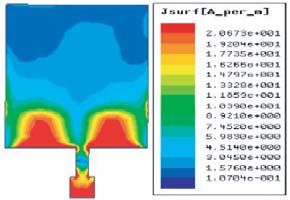
94                                                                                  Hazarika, Basu, and Nandi

Table 1. Optimized monopole parameters (Unit: mm).

                           Design
                                          Mw    Ml   mw1    mw2         ml1    ml2
                         Parameters
                           Values          34   34    6     3.2          5      7
                           Design
                                           gl   gw   dw      dl         gndl
                         Parameters
                           Values           5   20   11.5   40          20

2.4. Integration of Proposed AMC Antenna
The AMC integrated antenna and its prototype are presented in Figs. 4(a) and (b). The h air value is
moderately adjusted to produce better impedance matching and realized using foam spacers of height
5 mm and dielectric constant near 1 between the antenna and AMC layer at the four corners. The
monopole antenna is positioned on top of the AMC surface to attain in-phase reflection characteristics
at both the frequency bands. The reflection characteristic of the AMC layer mentioned in Fig. 5
suggests that the monopole can be positioned at 5 mm height above the AMC layer without affecting
its radiation efficiency [Fig. 8(b)] at the designated frequency. Considering the dimension of the feed
line and radiation analysis of the antenna, we have selected the AMC layer with a 2 × 2 unit-cell array
having the dimension of 57.77 × 59.71 mm2 . Fig. 1(b) shows the physical design of the dumbbell-shaped
2×2 AMC unit-cells array.

                                          (a)                     (b)

Figure 4. (a) Configuration of integrated antenna. (b) Prototype of fabricated antenna.

                                    (a)                                  (b)

Figure 5. (a) S11 and, (b) gain of integrated antenna.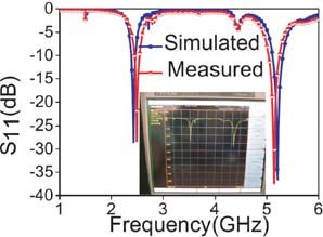
Progress In Electromagnetics Research C, Vol. 110, 2021                                              95

3. RESULTS AND DISCUSSION

The integration of monopole with the AMC is accomplished to improve the radiation performances.
According to Fig. 1(b), the AMC structure offers zero phase reflection at 2.5 GHz. The proposed
antenna also shows weak resonance at 2.5 GHz. AMC antenna provides excellent impedance matching
at 2.5 GHz. Again at 5.2 GHz, the space phase caused due to the gap between radiator and the AMC
modifies the effective reflection phase and establishes the impedance matching condition. The integrated
antenna also gives good front-to-back radiation ratio and co- and x-pol intensity difference up to 14 dB
for both the bands.

3.1. S11 Parameter
The S-parameters of the integrated antenna, measured by the Anritsu vector network analyzer
MS2037C, is exhibited in Fig. 5(a). Fig. 5(a) depicts that the simulated reflection coefficient bandwidth
equivalent to S11 < −10 dB is spaced at 2.38–2.47 GHz and 5.11–5.31 GHz. The monopole resonating
near 2.5 GHz ha used rectangular slot to make antenna layer inductive at 5.2 GHz which upon integration
with the capacitive AMC layer excites two resonating bands at 2.43 GHz and 5.2 GHz.

3.2. Gain, Radiation Pattern and FB Ratio
When the AMC layer with full ground at the back is located near the monopole, it functions as an infinite
layer, reduces the edge effect, and improves the spill over efficiency. The gain, radiation pattern, and
FBR of the integrated antenna are measured in an anechoic chamber with pyramidal shaped absorbers
using Anritsu MS2037 VNA. The slotted monopole placed at a distance 5 mm above the AMC surface
proffers gain nearly equal to 9.5 dB and 8.1 dB at both the bands as in Fig. 5(b) [13, 14]. Measured gain
of the AMC antenna shows maximum discrepancy of 0.6 dB compared to the simulated gain because of
fabrication error. The 2 × 2 array AMC effectively has transformed the spherical-like phase contour of
the radiated wave into in-phase planar pattern and enhanced the antenna gain. Without the slot the
AMC antenna offers 7.5 dB and 3.7 dB gains at the two bands.
     Figures 6(a)–(d) show the simulated and measured E- and H-field radiation features (far-field) of
the AMC integrated antenna at the two frequencies. At 2.43 GHz, the radiation intensity differences

                                    (a)                             (b)

                                    (c)                             (d)

Figure 6. Simulated and measured far-field distributions of AMC integrated antenna. (a) E-field and
(b) H-field at 2.43 GHz. (c) E-field and (d) H-field at 5.2 GHz.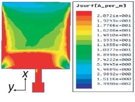
96                                                                           Hazarika, Basu, and Nandi

between E- and H-field co-x pol at broadside direction are 10.23 dB and 13.62 dB respectively. On the
other hand, the measured AMC antenna has E- and H-field radiation intensity differences between co-pol
and x-pol equal to 8.7 dB and 8.08 dB. At 5.2 GHz, the E- and H-field radiation intensity differences at
broadside direction are 11.15 dB and 12.21 dB, respectively. However, the measured E-field and H-field
radiation intensity differences at 5.2 GHz are 11.91 dB and 12.82 dB respectively [15]. The simulated and
measured radiation patterns are varied due to fabrication and cabling error, and air bubble is present
in the foam spacer.
     Figure 7 shows that the phase of the E-field is relatively stable within main lobe directions at
2.43 GHz and 5.2 GHz when the antenna is incorporated with the AMC. Thus the AMC layer nullifies
the out-of-phase radiation and improves radiation gain.

                                    (a)                              (b)

Figure 7. Phase center of integrated antenna at (a) 2.43 GHz and (b) 5.2 GHz.

     The integrated antenna gives FBR values of 6.3 dB at 2.43 GHz and 21.2 dB at 5.2 GHz
[Fig. 8(a)] [13]. The radiation efficiency values of the integrated antenna are 0.95 at 2.43 GHz and
0.985 at 5.2 GHz because of integration of AMC below the monopole, as displayed in Fig. 8(b).

                                    (a)                             (b)

Figure 8. Integrated antenna parameters. (a) FB ratio. (b) Radiation efficiency.

     Figures 9(a) and (b) present the current distributions on the antenna without slot at 2.43 GHz
and 5.2 GHz. Figs. 9(c) and (d) show the current distributions on the antenna slot at 2.43 GHz
and 5.2 GHz. Due to the slot on the monopole, the current path redistributes, and surface current
distribution depresses signifying that the antenna with slot radiates more electromagnetic energy.

4. CONFORMAL ANTENNA ANALYSIS

For WBAN application in real scenario, the antenna undergoes physical deformation, which is
approximated with different bending angles. Bending radii of Ra = 150 mm, 90 mm, 40 mm, 35 mm,
30 mm, 25 mm, 20 mm, and 15 mm are assigned to the AMC antenna, and the results obtained are
analyzed and presented in Fig. 10. We have also designed a reference patch antenna at 2.4 GHz for
evaluating the three bending responses. As we vary the bending radius from 150 mm to 15 mm for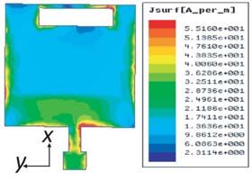
Progress In Electromagnetics Research C, Vol. 110, 2021                                           97

                                 (a)                            (b)

                                 (c)                            (d)

Figure 9. Simulated surface current distribution at (a) 2.43 GHz without slot, (b) 5.2 GHz without
slot, (c) 2.43 GHz with slot, (d) 5.2 GHz with slot.

                                       (a)                       (b)

                                       (c)                        (d)

Figure 10. (a) S11 of conformal integrated antenna. (b) Conformal prototype. (c) S11 of conformal
ref patch and (d) gain of integrated and ref patch for different Ra .

the AMC antenna, the 2.43 GHz frequency band shifts with the maximum deviation up to 0.09 GHz,
and the 5.2 GHz frequency band swings with the maximum deviation up to 0.24 GHz as represented in
Fig. 10(a). It is also observed from Fig. 10(a) that the S11 curve deteriorates as the bending radius
increases. The related conformal structure is shown in Fig. 10(b). For reference patch antenna, due
to bending, the peak resonant frequency shifts significantly to 2.64 GHz, 2.84 GHz, and 3.44 GHz from
2.4 GHz as in Fig. 10(c). It is seen from Fig. 10(d) that the broadside simulated gain profile of the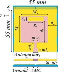
98 Hazarika, Basu, and Nandi
integrated antenna at Ra = 150 mm offers a peak gain of 8.4 dB and 7.5 dB at the dual frequency bands.
However, according to Fig. 10(d), the reference patch antenna suffers from substantial gain drop in the
respective bands owing to the shifting of resonating frequency due to bending and the broadening of the
radiation beamwidth. From this analysis, we can infer that the performances of both the structures,
original and conformal AMC based antennas, are in accordance well. It happens that as the antenna
is deformed around any surface, the effective length of the antenna increases. The integrated antenna
consists of two parts: the monopole antenna and AMC surface. When length increases, the monopole
becomes inductive, and AMC becomes capacitive. At resonances, the inductive and capacitive effects
nullify each other, and the antenna proffers robustness in bending.
5. IMPACT ON HUMAN BODY
The simulated and measured S11 of the antenna while being placed on the phantom model and on body
are exhibited in Fig. 11(a). While the integrated antenna is put on male phantom hand, the frequency
is shifted to 2.41 GHz and 5.12 GHz, respectively [Fig. 11(a)]. In the case of female phantom hand,
the frequency shifts to 2.42 GHz and 5.17 GHz [Fig. 11(a)], respectively. The conformal antenna, with
a bending radius of 150 mm, operates at 2.44 GHz and 5.28 GHz in free space. As the test antenna is
positioned on male and female phantom hands, the lower frequency band is shifted to 2.55 GHz and
2.48 GHz on male and female hands, respectively, as shown in Fig. 11(b). Again in the case of higher
operating frequency band, the operating frequency shifts to 5.18 GHz and 5.15 GHz as loaded on male
and female hands individually. This shifting occurs because of the dielectric variation of the antenna
in the presence of human tissues. A reference patch antenna operating at 2.4 GHz is also placed on
both male and female phantom hands. While the antenna is situated at 10 mm apart from the human
hand phantom, the operating frequency shifts to 3.25 GHz and 3.26 GHz for male and female hands,
respectively [Fig. 11(c)].
(a) (b) (c)
Figure 11. Simulated and measured S11 of integrated antenna on (a) flat and (b) bent condition, (c)
simulated S11 of patch antenna on bent and flat condition.
6. SAR EVALUATION FOR ARTIFICIAL HUMAN MODEL ANALYSIS
The Specific Absorption Rate (SAR) is the rate of EM power absorbed per unit mass of body tissues.
According to the IEEE C95.1-1999, SAR values should not be greater than 1.6 W/kg over 1-g of tissues.
Before utilizing the antenna for WBAN application, the SAR is calculated considering the input power
equal to 100 mW.
The amount of RF exposure on human body is related to the conductivity of the human tissues
(σ), mass density (ρ), and the intensity of the electric-field (E). As the absorbed power is associated
with the E-field to the highest extent, the maximum SAR value needs to be listed in the regions where
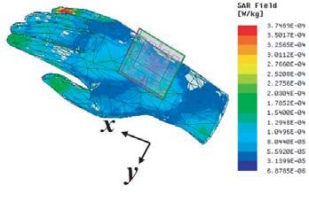
E-field strengths are maximum. An artificial multi-layered human tissue model as shown in Fig. 12 has
been used to perform the on body SAR analysis. This artificial model consists of skin, fat, muscle, and
bone with individual permittivity, conductivity, thickness, and mass-density values. To record SAR,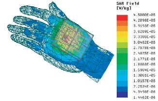
Progress In Electromagnetics Research C, Vol. 110, 2021                                                    99

Figure 12. Flat multi-layered human tissue model.

AMC-based antenna is located at 1 mm apart from the air-skin interface. The relative permittivity and
conductivity of different tissues at different frequencies due to the placement of the proposed antenna
are simulated using Debye model [16] and plotted in Fig. 13. Finally, the multi-layered tissue properties
including SAR values at two designated frequencies are listed in Table 2.

Table 2. Permittivity, conductivity and SAR values using Debye model.

        Human tissue
                                                          Debye model
           layers
                                           ε                        σ                 SAR (W/kg)
                          ε∞    2.43 GHz       5.2 GHz    2.43 GHz      5.2 GHz    2.43 GHz   5.2 GHz
             Skin          4    4.00002        4.00001    0.00267       0.00267      0.225     0.146
             Fat          2.5   2.50003        2.50002    0.00167       0.00167      0.21      0.14
           Muscle          4    4.00001        4.000002   0.00267       0.00267      0.247     0.124
            Bone          2.5   2.50002        2.500008   0.00167       0.00167      0.131    0.00453

7. SAR EVALUATION FOR HUMAN PHANTOM MODEL

As presented in Fig. 14, the human phantom model for hand developed by ANSYS HFSS is exploited
for testing. The separation (d) between the skin and AMC antenna is set at 10 mm. Table 3 presents
the SAR value of the flat and bent monopole and integrated antennas for 1-g of tissues at the respective
bands. It is seen that maximum SAR of the flat and bent antennas on male and female hands at 1-g
of tissues are below the existing regulations [13, 14] in all the cases. However, the SAR values of the
conformal antenna in every cases are slightly higher than that of the flat one. In comparison to the
monopole antenna alone: the SAR reduction acquired from the AMC antenna is 99.9% at 2.43 GHz

Table 3. Simulated SAR values of flat and bent (Ra = 150 mm) monopole and AMC integrated antenna
on human phantom hand (Unit: W/kg).

                       Flat (F) and Bent (B)                                      Bent (B) (Ra = 150 mm)
    Parameters                                      Flat (F) AMC antenna
                     (Ra = 150 mm) Monopole                                            AMC antenna
    Frequency          1-g             1-g            1-g          1-g             1-g           1-g
      (GHz)           (male)        (female)         (male)     (female)          (male)      (female)
   2.5 (Mono)/      0.404 (F)      0.682 (F)
                                                     0.00037    0.000833          0.0019       0.0091
  2.43 (Int) GHz    0.413 (B)      0.870 (B)
     5.2 GHz                                        0.000686    0.000893          0.00245      0.0288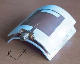
100                                                                         Hazarika, Basu, and Nandi

                           (a)                                        (b)

                           (c)                                        (d)

Figure 13. Permittivity and conductivity of tissues. (a) Skin, (b) fat, (c) muscle and (d) bone for
Debye model.

when it is on male hand. In the same environment, at 5.2 GHz, the reduction for 1-g body tissues
is 99.83%. In comparison to the deformed monopole antenna, the bent AMC antenna offers 99.5%
reduction at 2.43 GHz on male phantom. However, at 5.2 GHz, the curved AMC antenna achieved
99.4% reduction in SAR value with respect to the SAR of the monopole at 2.5 GHz, when it is on male
phantom hand. Table 4 compares the features of the proposed antenna in terms of S11 , gain, efficiency,
ka, and SAR values with those of the existing implantable antennas described in literature [6–9] and
substantiates the superiority of the proposed one. Here k = free-space wave number and a = radius of
the sphere confining the radiator [17]. In the proposed design, antenna has the ka value equal to 1.22
and considered as a compact antenna. So the antenna offers high Q value which gives high gain and
leads to lower BW of 3.7% and 3.8% at 2.43 GHz and 5.2 GHz.

               (a)                               (b)                               (c)

Figure 14. Simulated SAR of flat and bent AMC antenna at 2.43 GHz. (a) 1-g of tissues on male
hand. (b) 1-g of tissues on female hand. (c) 1-g on female hand at 5.2 GHz.
Progress In Electromagnetics Research C, Vol. 110, 2021 101
Table 4. Comparison of antenna characteristics described for WBAN applications.
Ref. No. Size Bands Gain Efficiency ka SAR
0.17 W/kg,
1.96 GHz, 4.668 dB,
0.178 W/kg,
[6] 0.190λ × 0.123λ 1.97 GHz, 4.693 dB, n/a 0.37
0.163 W/kg
1.98 GHz 4.722 dB
(10-g on hand)
0.22 W/kg,
5.2 GHz, 6.1 dBi, 92%,
[7] 1.12λ × 1.12λ 3.93 0.18 W/kg
5.8 GHz 5.9 dBi 91%
(1-g on head)
0.33 W/kg (1-g
[8] 0.316λ × 0.274λ 2.45 GHz 8.41 dBi 71% 1.15
on artificial layer)
2.48 W/kg,
2.45 GHz, 5.2 dB, 61.3%,
[9] 0.246λ × 0.2λ 0.51 3.33 W/kg (1-g
5.8 GHz 7.7 dB 67.2%
on forearm)
0.0683 W/kg,
3.5 GHz, 9.373 dB, 83.5%,
[13] 0.367λ × 0.486λ 1.89 0.333 W/kg (1-g
5.8 GHz 6.634 dB 96.5%
on hand)
0.22 W/kg (1-g
[14] 0.225λ × 0.146λ 2.45 GHz 6.51 dBi 74.8% 0.833
on hand)
0.00037 W/kg,
[Proposed 2.43 GHz, 9.5 dB, 95%,
0.492λ × 0.478λ 1.22 0.000686 W/kg (1-g
work] 5.2 GHz 8.1 dB 98.5%
on hand)
8. CONCLUSION
This paper has proposed a dual-band, wearable AMC integrated antenna for WBAN applications. It
utilizes a 2 × 2 array of dumbbell-shaped metallic sheet backed AMC for attaining higher gain and
lower SAR on human phantom hand. The realized antenna accomplishes higher gains of 9.5 dB and
8.1 dB and efficiencies of 95% and 98.3% at the two frequency bands. Co-pol and x-pol radiation
intensity differences of 10.23 dB and 11.15 dB for E-field and 13.62 dB and 12.21 dB for H-field have
been achieved at 2.43 GHz and 5.2 GHz, respectively. The multi-layered AMC has further reduced the
backward electromagnetic radiation and increases the FB radiation ratio up to 6.3 dB and 21.2 dB at
lower and upper frequency bands, respectively. Different conformal performances have demonstrated
the robustness of the antenna. The impact of the human body loading of the integrated antenna is
investigated using Debye model. While the monopole is integrated with AMC, the SAR performance
decreases more than 95% on both flat and bent conditions, which is enough within the limits specified
by ICNIRP.
REFERENCES
1. Zhai, H., K. Zhang, S. Yang, and D. Feng, “A low-profile dual-band dual-polarized antenna with an
AMC surface for WLAN applications,” IEEE Antennas and Wireless Propagation Letters, Vol. 16,
2692–2695, 2017.
2. Mersani, A., L. Osman, and J.-M. Ribero, “Performance of dual-band AMC antenna for wireless
local area network applications,” IET Microwave and Antenna Propagation, Vol. 12, No. 6, 872–878,
2018.102 Hazarika, Basu, and Nandi
3. Misra, P., S. S. Pattnaik, W. Cao, S. Shi, Q. Wang, and W. Zhong, “Metamaterial loaded fractal
based interdigital capacitor antenna for communication systems,” Progress In Electromagnetics
Research M, Vol. 16, 2473–2476, 2018.
4. Ayd, A. and R. Rad, “Low-profile MIMO antenna arrays with left-handed metamaterial structures
for multiband operation,” Progress In Electromagnetics Research M, Vol. 89, 1–11, 2020.
5. Moreira, E. C., R. O. Martins, B. M. S. Ribeiro, and A. S. B. Sombra, “A novel gain-enhanced
antenna with metamaterial planar lens for long-range UHF RFID applications,” Progress In
Electromagnetics Research B, Vol. 85, 143–161, 2019.
6. Kwak, S. I., D.-U. Sim, J. H. Kwon, and Y. J. Yoon, “Design of PIFA with metamaterials for body-
SAR reduction in wearable applications,” IEEE Transactions on Electromagnetic Compatibility,
Vol. 59, No. 1, 297–300, 2017.
7. Cao, Y. F., X. Y. Zhang, and T. Mo, “Low-profile conical-pattern slot antenna with
wideband performance using artificial magnetic conductors,” IEEE Transactions on Antennas and
Propagation, Vol. 66, No. 5, 2210–2218, 2018.
8. Alemaryeen, A. and S. Noghanian, “Crumpling effects and specific absorption rates of flexible AMC
integrated antennas,” IET Microwave and Antenna Propagation, Vol. 12, No. 4, 627–635, 2018.
9. Wang, M., Z. Yang, J. Wu, J. Bao, J. Liu, L. Cai, T. Dang, H. Zheng, and E. Li, “Investigation of
SAR reduction using flexible antenna with metamaterial structure in wireless body area network,”
IEEE Transactions on Antennas and Propagation, Vol. 66, No. 6, 3076–3086, 2018.
10. Lee, H., J. Tak, and J. Choi, “Wearable antenna integrated into military berets for indoor/outdoor
positioning system,” IEEE Antennas and Wireless Propagation Letters, Vol. 16, 1919–1922, 2017.
11. Hazarika, B., B. Basu, and A. Nandi, “Design of antennas using artificial magnetic conductor
layer to improve gain, flexibility, and specific absorption rate,” Microwave and Optical Technology
Letters, Vol. 62, No. 12, 3928–3935, 2020.
12. Hazarika, B., B. Basu, and A. Nandi, “An artificial magnetic conductor-backed monopole antenna
to obtain high gain, conformability, and lower specific absorption rate for WBAN applications,”
International Journal of RF and Microwave Computer-aided Engineering, Vol. 30, No. 12, 1–9,
2020.
13. Atrash, M. E., M. A. Abdalla, and H. M. Elhennawy, “A wearable dual-band low profile high gain
low SAR antenna AMC-backed for WBAN applications,” IEEE Transactions on Antennas and
Propagation, Vol. 67, No. 10, 1–10, 2019.
14. Atrash, M. E., M. A. Abdalla, and H. M. Elhennawy, “A compact highly efficient-section CRLH
antenna loaded with textile AMC for wireless body area network applications,” IEEE Transactions
on Antennas and Propagation, doi: 10.1109/TAP.2020.3010622.
15. Ghosh, A., S. Chakraborty, S. Chattopadhyay, A. Nandi, and B. Basu, “Rectangular microstrip
antenna with dumbbell shaped defected ground structure for improved cross polarised radiation
in wide elevation angle and its theoretical analysis,” IET Microwave and Antenna Propagation,
Vol. 10, No. 1, 1–11, 2016.
16. Gabriely, S., R. W. Lau, and C. Gabriel, “The dielectric properties of biological tissues: III.
Parametric models for the dielectric spectrum of tissues,” Physics Medical Biology, Vol. 41, No. 11,
2271–2293, 1996.
17. Sievenpiper, D. F., D. C. Dawson, M. M. Jacob, T. Kanar, S. Kim, J. Long, and R. G. Quarfoth,
“Experimental validation of performance limits and design guidelines for small antennas,” IEEE
Transactions on Antennas and Propagation, Vol. 60, No. 1, 8–19, 2012.You can also read