Measurement method of pillow spring based on machine vision
←
→
Page content transcription
If your browser does not render page correctly, please read the page content below

Journal of Physics: Conference Series

PAPER • OPEN ACCESS

Measurement method of pillow spring based on machine vision
To cite this article: Huanlong Liu et al 2021 J. Phys.: Conf. Ser. 1986 012118

View the article online for updates and enhancements.

                                This content was downloaded from IP address 46.4.80.155 on 10/09/2021 at 17:54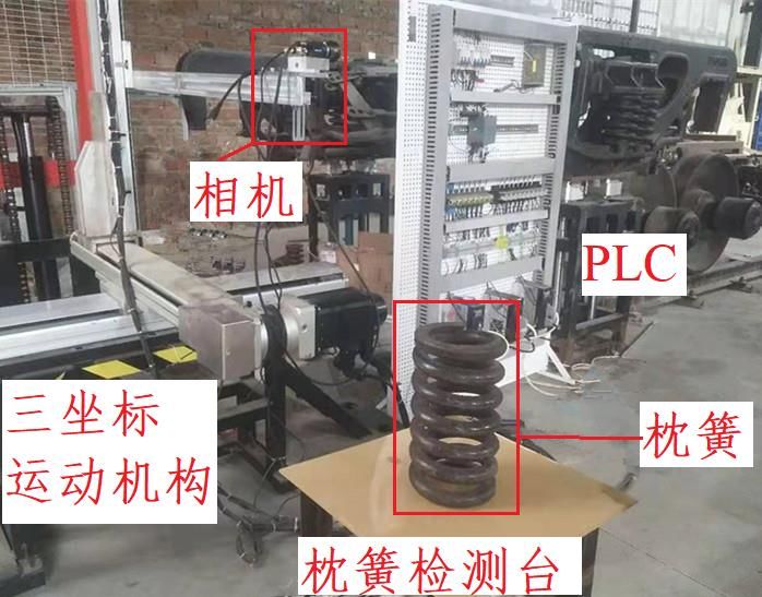
MMEAT 2021                                                                                                      IOP Publishing
Journal of Physics: Conference Series                         1986 (2021) 012118          doi:10.1088/1742-6596/1986/1/012118

Measurement method of pillow spring based on machine
vision

                     Huanlong Liu1a, Bin Jiang2b*,Dafa Li1c, Zhengjie Wang2d
                     1
                         School of Mechanical Engineering, Southwest Jiaotong University, Chengdu, China
                     2
                         Graduate Tangshan Institute, Southwest Jiaotong University, Tangshan , China
                     a
                      email: lhl_swjtu@163.com, cemail: 1754709736@qq.com, demail:
                     798925153@qq.com
                     *bemail: jiangbin93@my.swjtu.edu.cn

                     Abstract: In the current maintenance of pillow springs of railway freight cars in our country,
                     the measuring method of manually using measuring scale and measure gauges is still common.
                     In order to improve the quality and efficiency of the pillow spring measurement, and to support
                     the automatic upgrade of the pillow spring maintenance line, a new method for measuring the
                     size of the pillow spring based on machine vision is proposed. By analyzing the requirements
                     and characteristics of pillow spring detection and matching, a visual measurement system was
                     designed to replace manual measurement, and openCV was used for image processing, feature
                     extraction and size calibration.Compared with manual measurement, the measurement
                     accuracy and efficiency of this method are higher. Experiments were conducted under different
                     lighting conditions, and the measurement results have good repeatability and stability,
                     indicating that the method has good robustness to the light intensity of the pillow spring
                     environment.

1.Introduction
Damping springs and bolster springs are collectively called pillow springs, which are an important part
of railway freight car bogies and are mainly used to dampen the vibration and impact of railway
freight cars in operation. According to the requirements of "Regulations for Repair of Railway Freight
Cars", the pillow springs of railway freight car bogies need to be overhauled regularly [1], which
mainly include the height of the pillow spring, the diameter of the round steel and the size difference
between different pillow springs. According to the measurement results, select the pillow spring
combination.
    The traditional detection method is to measure the height of the pillow spring with a ruler, and
measure the diameter of the pillow spring with a gauge. There are many types of bogie bolster springs.
The existing operating methods are low in efficiency, labor intensive, and are interfered by human
factors. Therefore, there is an urgent need to develop automated measurement equipment to replace
labor. CRRC Qiqihar Company has developed a mechanical bolster spring geometric tolerance
measurement platform [2], which has better measurement accuracy and stability than manual
measurement. Shenhua Railway Freight Transport Co., Ltd. has developed an intelligent detection
system for sleeper springs based on 3D structured light technology [3]. For the measurement of the
outer diameter of the pillow spring, there are relatively few research reports based on the machine
vision measurement method. However, geometric measurement technology based on machine vision
              Content from this work may be used under the terms of the Creative Commons Attribution 3.0 licence. Any further distribution
              of this work must maintain attribution to the author(s) and the title of the work, journal citation and DOI.
Published under licence by IOP Publishing Ltd                          1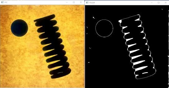
MMEAT 2021                                                                                  IOP Publishing
Journal of Physics: Conference Series          1986 (2021) 012118     doi:10.1088/1742-6596/1986/1/012118

has begun to be applied in fields such as mechanical parts and agricultural products.For example, the
paper [4-7] proposed some machine vision-based dimensional inspection technologies for bearing inner
and outer rings, aviation rivets, brake pads and other workpieces; The paper [8] improves the accuracy
of the bearing measurement by improving the median filter; the paper [9] compares the image of the
standard part with the image of the measured part to measure the machining error of the workpiece; in
the paper [10-12] Applying machine vision technology to the size and shape detection and classification
of mango, perilla leaves and corn; Paper [13] designed a machine vision-based measurement method for
the end face size of turnout rail parts; In the paper [14], a double projection-based hole size
measurement method was proposed. The phase shift method is used to calculate the phase of the
grating image in two directions, and the reconstructed 3D shape in two directions is combined to
measure the hole size.
   The existing pillow spring measurement technology has low work efficiency and is difficult to
adapt to the intelligent development of bogie maintenance. Due to the special structural characteristics
of the pillow spring and the complicated measurement environment, the existing measurement
methods based on machine vision technology are difficult to be fully applicable. Therefore, for the
specific detection object of the pillow spring, this paper studies and designs a method for measuring
the size of the pillow spring based on machine vision technology, which realizes the measurement of
the free height and diameter of the pillow spring.

2. System design and workflow
This vision measurement method is mainly composed of an image acquisition system, an image
processing and analysis system. The Fig. 1 is pillow spring and image acquisition system;Fig. 2 is a
flow chart of the implementation of the method scheme; Fig. 3 is a flow chart of the image processing
system algorithm.

                                                              camera
                                                                                             PLC

                                                motion                                         pillow
                                                mechanism                                      spring

                                                                         Measurement
                                                                         platform
           (A)Pillow spring                                         (B) Image acquisition system
                            Fig. 1 Pillow spring and image acquisition system

   As shown in Fig. 1(A), the picture shows the detected target pillow spring. In this method, the
diameter of the end face of the pillow spring and the free height of the pillow spring are measured
respectively. Fig. 1 (B) shows the image acquisition system, and its main components are the camera,
the pillow spring detection platform, the PLC controller, and the three-coordinate motion system. Fig.
2 shows that the specific detection process is: realize the movement of the camera through the
three-coordinate motion system; after obtaining the image of the detection target, the image processing
algorithm is used to obtain the corresponding size information and display and output.In this method,

                                                    2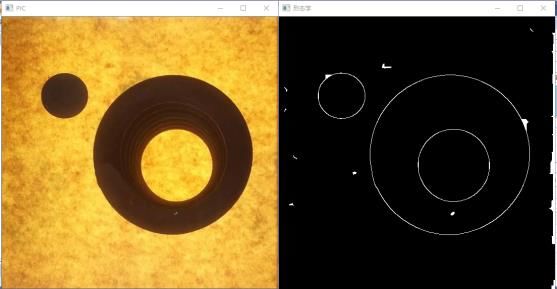
MMEAT 2021                                                                                IOP Publishing
Journal of Physics: Conference Series          1986 (2021) 012118   doi:10.1088/1742-6596/1986/1/012118

the camera used is a 5 million pixel CCD camera with model GMT200-H, and the lens model is
SA1620M-10MP. In order to ensure the image quality, the backlighting scheme is used for light source
compensation in this method. The measured target pillow spring is placed between the light source and
the camera. The measured target body is a black shadow in the collected image, which can be
displayed to the greatest extent. The edge profile of the pillow spring. In this method, the work surface
on which the pillow spring is placed is made of transparent acrylic material.

                               Fig. 2 Flow chart of scheme implementation

3. Image preprocessing

                         Fig. 3 Algorithm flow chart of image processing system

Fig. 3 is a flowchart of the image processing system algorithm of the method. In the process of image
acquisition by the system, factors such as the camera's shooting angle, lens distortion, and pillow
spring position will cause errors in the final measurement results. Therefore, in the image processing
process, the image needs to be corrected. Then through a series of morphological processing, the
image noise is reduced in order to accurately find the contour of the pillow spring. Finally, edge
extraction, contour fitting and size calculation are performed on the image.

                                                    3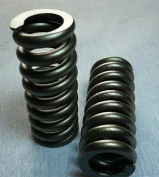
MMEAT 2021 IOP Publishing
Journal of Physics: Conference Series 1986 (2021) 012118 doi:10.1088/1742-6596/1986/1/012118
3.1 Image correction
In order to improve the measurement accuracy of the pillow spring size, reduce the camera angle and
the distortion of the camera lens itself. This method uses Zhang Zhengyou calibration method to
correct the image. First, use the camera to take 20 images of the chessboard at different angles. The
chessboard is a grid of alternating black and white, and the number of corners of the chessboard is
11*11. Then, sub-pixel positioning method is used to detect and draw the corners in the chessboard.
The detected corner points are added to the vector of coordinate points, and the calibration parameter,
which is the distortion matrix, is calculated. The calibration model between the world coordinate
system and the camera coordinate system can be expressed as:
u x
v = G y ⑴
w z
Where,the M (x, y, z ) is pixel in the world coordinate system; m(u, v, w) is the pixel in the camera
coordinate system; G is the distortion correction matrix.
The result of matrix G can be obtained by calibration:
1 1
0
x
x
1 1
G= 0 ⑵
y y
0 0 1
3.2 Image brightness correction
Due to the complexity of the actual measurement environment, the light source compensation
equipment cannot completely avoid the unevenness of illumination. In order to reduce the influence of
uneven illumination on the subsequent image preprocessing results, this method uses a brightness
equalization algorithm to correct the brightness of the image, so that the brightness of the image is
more balanced.
The principle of the brightness equalization algorithm is as follows: Assuming the image of
M N , the gray level is (0, , L ) . Then the average brightness is:
M =1 N =1
p(i, j )
i =0 j =0
Lumav = ⑶
M N
Among them, p(i, j ) is the brightness value of the pixel with coordinate (i, j ) in the image.
The image is divided by the size of m n , and the average brightness of each sub-region is:
m =1 n =1
p(i, j )
i =0 j =0
Lum av _ bm = ⑷
m n
From (3) and (4), the difference between the average brightness of the sub-region and the average
brightness of the whole image can be obtained as: lum = Lumav _ bm − Lumav .
Through the adjustment of Lum , makes the brightness between adjacent sub-regions smooth.
3.3 Morphological processing
In order to reduce the amount of data in the image processing process, improve the effect of edge
fitting and extraction. This method performs binarization processing on the collected original image to
4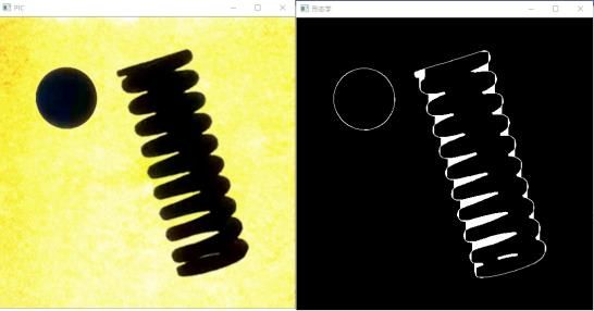
MMEAT 2021 IOP Publishing
Journal of Physics: Conference Series 1986 (2021) 012118 doi:10.1088/1742-6596/1986/1/012118
better display the characteristic contour of the pillow spring.
Fig. 4 shows the original image captured by the camera and the image after binarization. The
binary mathematical model is:
255, f (i, j ) T
g (x, y ) =
0, f (i, j ) T ⑸
Where, g (x, y ) is the value of pixel (x, y ) in the binarized image; , is the gray value range of
the original image f (i, j ) ; T is the global threshold, and. T .
Fig. 4 Original image and binary image
Fig. 5 shows the optimization effect diagram of the three edge detection algorithms of canny, sobel,
and Laplacian. As shown in Fig. 5, the edge detection effect of the canny and Laplacian algorithms is
significantly better than the sobel algorithm.
(A) Canny (B) Sobel (C) Laplacian
Fig. 5 Canny、Sobel、Laplacian effect picture
Fig. 6 shows the edge lines of Canny and Laplacian edge detection algorithms. In the figure, the
Canny algorithm has a clearer edge than the Laplacian algorithm, and the edge of the Canny algorithm
is composed of one pixel, while the Laplacian algorithm is composed of three pixels. The Canny
detection algorithm indicates that the edge is more accurate and is as close as possible to the actual
edge. This method uses the canny algorithm for edge detection.
(A)Canny (B) Laplacian
Fig. 6 Canny、Laplacian edge line
The Canny edge detection algorithm is mainly based on the first and second derivatives of the
image, but the derivatives are usually very sensitive to noise, so filters must be used to improve the
performance of noise-related edge detection. This method uses Gaussian filtering to eliminate noise,
that is, a discretized Gaussian function is used to generate a set of normalized Gaussian kernels, and
5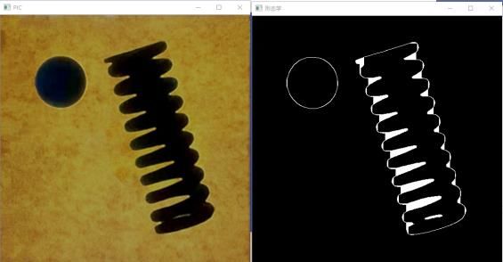
MMEAT 2021 IOP Publishing
Journal of Physics: Conference Series 1986 (2021) 012118 doi:10.1088/1742-6596/1986/1/012118
then a weighted sum of each point of the image gray matrix is performed based on the Gaussian kernel
function. The steps and principles are as follows:
Step 1:The image is smoothed and filtered by the Gaussian function G(i, j ) , g (i, j ) is the filtered
and smoothed image, f (x, y ) is the original image. Its mathematical model is expressed as:
i2 + j2
G(i, j ) =
1
exp − ⑹
2 2 2 2
g (i, j ) = G(i, j ) * f (x, y ) ⑺
Where, is the standard deviation of Gaussian function; * is the symbol of convolution operation.
The first-order differential operator of g (i, j ) in the x, y direction is as follows:
f (x + 1, y ) − f (x, y ) + f (x + 1, y + 1) − f (x, y + 1)
Gx = ⑻
2
f (x, y + 1) − f (x, y ) + f (x + 1, y + 1) − f (x + 1, y )
Gy = ⑼
2
Where, Gx and G y are the first-order differentials of the smooth image g (x, y ) in the x and y
directions.
From ⑽ and ⑾, the gradient amplitude M (x, y ) and the gradient direction (x, y ) can be
obtained.
M (x, y ) = Gx2 + G y2 ⑽
Gy
(x, y ) = arctan
⑾
G x
Step 2:In order to exclude non-edge pixels, only candidate edges are retained. The interpolation
method is used to suppress the non-maximum value of local pixels. Find the local maximum of a pixel,
set the gray value corresponding to all non-maximum points as the background pixel, and the local
optimum of the gradient value in the neighboring area of the pixel will be judged as the edge of the
pixel. Relevant information of other non-maximum values is suppressed, and most non-edge points are
proposed using this criterion.
Step 3:In order to determine the final edge pixel point, it is necessary to set the hysteresis threshold.
The high threshold set in this method is H = 100 , and the low threshold is L = 50 . If the amplitude
of a certain pixel position is H , the pixel will be reserved as an edge pixel; If the amplitude of a
certain pixel position is L , then the pixel is excluded; if the amplitude of a certain pixel position
is L H , then the pixel will only be retained if it is connected to a pixel higher than a high
threshold.
4. Feature extraction and size acquisition
In this method, the outline diameter r1 of the reference object in the image is obtained by the smallest
outer rectangle, Contour diameter of pillow spring image R1 and the height of the pillow spring
H1 .Finally, the height H and contour diameter R of the pillow spring are obtained from the ratio
.
4.1 Extract contour
In order to accurately extract the contours of the reference object and the pillow spring, this method
traverses the detected contours in sequence. The area size of the extracted contour area is checked to
avoid the interference of image noise, and the final contour area is circumscribed. As shown in Fig.7,
the left side of the figure is the reference object, and the right side is the detection target body pillow
spring. The green rectangle is the circumscribed rectangle of the outline.
6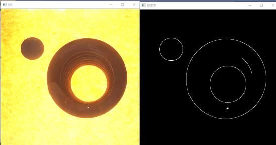
MMEAT 2021 IOP Publishing
Journal of Physics: Conference Series 1986 (2021) 012118 doi:10.1088/1742-6596/1986/1/012118
Fig. 7 Geometric model
4.2 System size calibration
The size of the pillow spring in the image is obtained by calculating the Euclidean distance between
two pixels, and then the actual size of the pillow spring is obtained by the ratio . The ratio is the
ratio of the pixel width of the object to the true width of the object. The reference object in this method
is uniquely identifiable in any case.
The calculation formula of the ratio is as follows:
= r1 / r0 ⑿
Where, is ratio. That is, the ratio of the pixel size to the real size; r1 is the pixel size of the
calibration object; r0 is the actual size of the calibration object, r0 = 38mm 。
4.3 size parameters
After edge detection and feature extraction, the contour diameter R1 of the pillow spring image and
the height H1 of the pillow spring can be obtained through the smallest circumscribed rectangle of
the contour. From ⑿, the dimensions R and H of the pillow spring can be obtained, as shown in
the following formula:
R = R1 ⒀
H = H1 ⒁
Where, R 、 H is the size of the pillow spring; R1 、 H1 is the pixel size of the pillow spring.
5. Analysis of measurement results
In this test experiment, the hardware platform configuration used is:Intel i7-3632QM CPU. The
software environment is configured as: Visual Studio 2017 and OpenCV 4.1.1。
In order to verify the reliability of this measurement method under different lighting conditions, the
same pillow spring was measured at different times. In order to ensure the accuracy of the data and
reduce the interference data, the positions of the camera and the pillow spring of the target detection
body are fixed during the image acquisition process in this article.
(A) (B)
7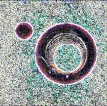
MMEAT 2021                                                                                IOP Publishing
Journal of Physics: Conference Series          1986 (2021) 012118   doi:10.1088/1742-6596/1986/1/012118

                         (C)                                                   (D)

                            (E)                                                   (F)
                      Fig. 8 Edge detectiont results under different light conditions

   Fig. 8 shows the edge detection results under three typical lighting conditions. As shown in Fig. 8,
affected by the lighting conditions, the edge detection results obtained under different lighting
conditions are different, and the final measurement results are also affected to a certain extent.Take
three different pillow springs to measure under three light conditions. The measurement results of the
free height and diameter of the pillow spring are shown in Table 1.

              Table 1 Measurement results of pillow spring under different light conditions
                                                 Manual          Visual measurement results
                               Measurement
                Sample                         measurement         under different lighting
                                  items
                                                 (mm)                conditions(mm)
                                   Height           250         249.19     252.81    251.20
               Sample 1
                                  Diameter          138         139.87     140.31    138.75
                                   Height           262         263.72     262.43    262.98
               Sample 2
                                  Diameter          125         126.89     125.52    125.05
                                   Height           232         233.51     233.79    234.93
               Sample 3
                                  Diameter          148         148.23     149.59    149.09

   As shown in Table 1, the measurement error under different lighting conditions is also different
under the influence of lighting conditions. The error range is within mm, which can meet the
requirements of pillow spring measurement.
   To test the stability of the measurement accuracy of this method. Under the same conditions, the
visual measurement method and the vernier caliper were used to repeatedly measure the contour
diameter and free height of the same sample. The measurement results are shown in Fig. 9.

                                                    8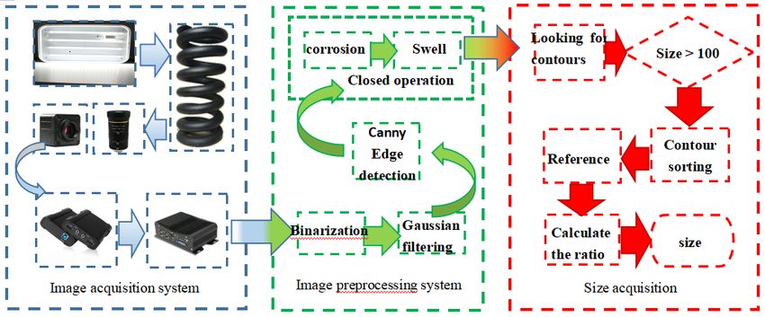
MMEAT 2021                                                                                IOP Publishing
Journal of Physics: Conference Series          1986 (2021) 012118   doi:10.1088/1742-6596/1986/1/012118

                          Fig. 9 Measurement results of outer contour diameter

                            Fig. 10 Measurement results of unsupported height

   In Fig. 9 and Fig. 10, the abscissa axis represents the number of measurements, and the ordinate
axis represents the measured value. It can be seen from the measurement results shown in the figure
that the measurement results of the two methods are relatively close. Affected by various
environmental factors, the results of manual measurement and visual image measurement have a
certain degree of error. The visual image measurement method is more efficient than the manual
measurement method using a vernier caliper, and meets the accuracy requirements.

6. Conclusions
⑴ In this paper, a method for measuring the size of pillow springs based on visual images is designed.
In the image acquisition system, the light source is assisted by backlighting, so that the edge of the
pillow spring is clear, and the effect of the original image is guaranteed to the greatest extent. In the
process of image preprocessing, distortion correction is performed on the image by the method of
checkerboard grid, and the morphological processing algorithm of brightness correction and Gaussian
filtering is used to remove the interference noise in the image. The canny edge detection algorithm is
used to obtain the contour edge, the minimum contour matrix and the reference object to realize the
measurement of the free height and diameter of the pillow spring.
    ⑵ Compared with the traditional contact-type pillow spring size measurement method, the
accuracy and repeatability of the measurement results obtained by this measurement method in the
actual test are basically the same as those obtained by manual vernier calipers. In terms of efficiency
and scalability, the visual image measurement method is better than the traditional measurement
method.

                                                    9
MMEAT 2021 IOP Publishing
Journal of Physics: Conference Series 1986 (2021) 012118 doi:10.1088/1742-6596/1986/1/012118
⑶ In practical engineering applications, due to the limitations of actual environmental factors and
the conditions of the pillow spring, it is difficult to achieve high-precision measurement based on the
machine vision-based size measurement method of the pillow spring. In-depth research is needed to
improve the accuracy of edge detection.
References
[1] TG/CL111-2012, Ailway Freight Car Depot Repair Specification.
[2] Kang, C.X., Xu, W. (2016) Development of geometric tolerance testing platform for cylindrical
sleeper spring of bogie. J .MW Metaal Cutting., S1. 208-210.
[3] Duan, L., (2017) Intelligent detection system of pillow spring. J. New Technology & New Products
of China, 24. 32-33.
[4] Xing, X.L., Gan, W.B., Jiang, C.C., (2020) Technology of Size Detection of Air Rivets Based on
Machine Vision. J. Acta Metrologica Sinica, 41(05): 518-523.
[5] Zhang, B., Li, H.X., Liu, D, et al. (2018) An Accurate Dimension Measuring Method of the
Cylindrical End Face in Complex Background. J. Journal of Zhengzhou University (Natural
Science Edition), 50(04). 70-74+100.
[6] Fan, S., Tang, Y.T., LU M.h.. (2016) Detecting and Classifying the Inner-outer Ring Sizes of
Bearings Based on Machine Vision.J. Process Automation Instrumen-tation,
37(11).77-80+87.
[7] Zhang, W. Y., Liu, X. J., Zhang, M.. (2017) Research on the Size Measurement of Porous Parts
Based on Machine Vision. C. In:2017 12th IEEE Conference on Industrial Electronics and
Applications (ICIEA), 242-247.
[8] Zhang, L. G., Yang, Q. L., Su, Q., aet al. (2019) Research on the size of mechanical parts based on
image recognition. J. Journal of Visual Communication and Image Representation, 59.
[9] Xiang, R., He, W.H., Zang X.N., aet al. (2018) Size measurement based on a two-camera
machine vision system for the bayonets of automobile brake pads. J. Measurement, 122-127.
[10] Chandra, S.N., Bipan, T., Chiranjib K.. (2016) A Machine Vision Technique for Grading of
Harvested Mangoes Based on Maturity and Quality. J. IEEE Sensors Journal, 16(16). 21-26.
[11] Zhao, B., Wang, Y,, Fu, Ju., et al. (2020) Online Measuring and Size Sorting for Perillae Based on
Machine Vision. J. Journal of Sensors.
[12] Wu, G., Wu Y.F., Chen, D., et al. (2020) Measurement Method of Maize Ear Characters Based on
Machine Vision. J. Transactions of The Chinese Society of Agricultural Machinery,
51(S2).357-365.
[13] Dou, Y., Zheng, Y.Q., Liu, H.Z., Dai, P.. (2015) Size measuring of the end surface of turnout rail
parts based on machine vision. C. In:2015 Seventh International Conference on Measuring
Technology and Mechatronics Automation. pp.991-994.
[14] Jin, Y., Chang, Y.M. Wang, J,Y. et al. (2020) The Measurement Method for the Size of the Hole
on the Part Surface Based on Grating Image Processing. J. IEEE Access, 8. 29159-29168.
10You can also read