Science Arts & Métiers (SAM) - Science Arts & Métiers (SAM)
←
→
Page content transcription
If your browser does not render page correctly, please read the page content below

Science Arts & Métiers (SAM)
    is an open access repository that collects the work of Arts et Métiers Institute of
  Technology researchers and makes it freely available over the web where possible.

             This is an author-deposited version published in: https://sam.ensam.eu
                          Handle ID: .http://hdl.handle.net/10985/20777

To cite this version :

B. ZHAO, J. GONG, T. TONG, Y. XU, E. SEMAIL, N. -K. NGUYEN, F. GILLON - A Novel Five-
Phase Fractional Slot Concentrated Winding with Low Space Harmonic Contents - IEEE
Transactions on Magnetics - Vol. 57, n°6, p.5 - 2021

Any correspondence concerning this service should be sent to the repository
                Administrator : archiveouverte@ensam.eu
IEEE TRANSACTIONS ON MAGNETICS, VOL. 57, NO. 6, JUNE 2021                                                                                             8104605

        A Novel Five-Phase Fractional Slot Concentrated Winding
                  with Low Space Harmonic Contents
             B. Zhao1, J. Gong           1,   T. Tong1,2, Y. Xu        1,   E. Semail      3,   N.-K. Nguyen        3,   and F. Gillon3
                             1
                         School of Electrical Engineering, Shandong University, Jinan 250061, China
2
    HEI, EA 2697-L2EP-Laboratoire d’Electrotechnique et d’Electronique de Puissance, Univ. Lille, Arts et Métiers ParisTech,
                                              Centrale Lille 59000 Lille, France
                      3
                        State Grid Jiangxi Electric Power Research Institute, Nanchang 330096, China

   In this article, a novel five-phase fractional-slot concentrated winding (FSCW) with 20-slot/22-pole is presented. It benefits not
only the advantages of conventional FSCW but also weak space harmonics of magnetomotive force (MMF). The winding allows
eliminating the first sub-order harmonic. The new layout of the winding topology is obtained by a combination of stator shift
technique of the winding in the slots with a special coupling of the windings (star-pentagon), using winding function theory. The
high performances of the new winding layout are validated using the finite element method (FEM). Compared to the conventional
winding, the winding factor and the total harmonic distortion (THD) of MMF are improved by 1.3% and 2.2%, respectively. With
the same injection of current density, the average output torque is increased by 1% and the torque ripple is decreased by 60%.
The eddy current losses in the permanent magnets (PMs) at rated speed (600 r/min) and 2100 r/min speed are improved by 67%
and 56%, respectively.
    Index Terms— 5-phase permanent magnet (PM) machine, finite element analysis, low-harmonic contents.

                          I. I NTRODUCTION                                      integrated with an optimization algorithm for the winding
                                                                                design in [14] and [15]. A higher number of layers (≥3)
F    RACTIONAL-SLOT concentrated winding (FSCW) are
     widely applied in electrical machines, due to the advan-
tages of short end windings, high power density, high effi-
                                                                                can also be used for the reduction of dominant loss-producing
                                                                                harmonics [16], [17]. However, with the increase of the layer
                                                                                number, the winding becomes more complex to realize. In this
ciency, high slot-filling factor, small cogging torque, etc.,                   article, based on the stator shift technique but with the end-
[1], [2]. Numerous commercial three-phase traction motors                       winding non-overlapping, a new topology of five-phase FSCW
with FSCW can be found, such as Honda (24 slots/16 poles),                      with selective harmonic elimination is proposed by combining
Bosch (36 slots/ 24 poles), Hyundai (24 slots/16 poles), and                    the star and pentagon coils connection [18]. This method can
Toyota (12 slots/8 poles). In the case of multiphase machines,                  also be extended to any number of phase winding design.
more choices of slot/pole combinations of FSCW can be made,                        This article will be organized as follows. In Section II,
which provides more possibilities for the requirement of the                    the basic structure of the traditional five-phase 20-slot/
machine performance [1].                                                        22-pole winding with MMF harmonics presentation is intro-
   One of the main challenges of FSCW is the rich content of                    duced, and the derivation process of the proposed new winding
space harmonics of magnetomotive force (MMF), including                         topology layout using winding shift technology is introduced.
both sub- and high-orders. These parasite harmonics can                         In Section III, the finite element method (FEM) is used to
lead to local core saturation [3], Eddy current loss, vibration                 verify the high performance of machines with the proposed
and noise, etc., which deteriorate the performance of the                       winding topology.
machine, especially for high-speed applications. Therefore,
many research studies have been made to avoid the bad                                II. D ERIVATION P ROCESS OF N EW W INDING W ITH
selection of slot/pole combinations [4], [5]. In addition, to fur-                           L OW MMF H ARMONIC C ONTENTS
therly reduce or eliminate parasitic harmonics of classical
slot/pole combinations of FSCW, various techniques have been                    A. Conventional 20-Slot/22-Pole Winding
proposed [6]. Stator shifting method is the most common one,                       For electrical machines with FSCW, the relationship
which can significantly reduce the loss-producing harmonics                     between the slot number (Q) and the pole number (2 p),
and improve the flux weakening performance by extending the                     i.e., 2 p = Q ± 2, is often satisfied to obtain high flux linkage
one slot coil pitch to two slots [7]–[9]. The effectiveness of                  and torque density. Therefore, a five-phase winding topology
this method was also validated with multiphase machines in                      in [19] is chosen here as a reference to present the new method,
[10] and [11]. Unfortunately, the end-winding is overlapped,                    which can be used to eliminate the parasite harmonics of
which makes the winding production more complex. Unequal                        MMF. The method can be easily extended to other similar
tooth widths technique is proposed in [12] and [13] and                         slot/pole combinations of different phases. Fig. 1(a) shows the
                                                                                structures of the outer-rotor 5-phase/20-slot/22-pole permanent
  Manuscript received November 30, 2020; revised December 29, 2020 and          magnet synchronous machines (PMSMs) with conventional
January 28, 2021; accepted January 31, 2021. Date of publication February 8,    winding configuration, which can be used for in-wheel traction
2021; date of current version May 17, 2021. Corresponding author: J. Gong       application. The windings of different phases are distinguished
(e-mail: gongjinlin@sdu.edu.cn).
  Color versions of one or more figures in this article are available at
                                                                                by color and the A-phase winding is marked as an example.
https://doi.org/10.1109/TMAG.2021.3057650.                                      It can be noted that the winding of each phase consists of four
  Digital Object Identifier 10.1109/TMAG.2021.3057650                           coils which can be connected in series or parallel.
                       0018-9464 © 2021 IEEE. Personal use is permitted, but republication/redistribution requires IEEE permission.
                                     See https://www.ieee.org/publications/rights/index.html for more information.

          Authorized licensed use limited to: UNIVERSITE DE LILLE. Downloaded on July 30,2021 at 16:22:02 UTC from IEEE Xplore. Restrictions apply.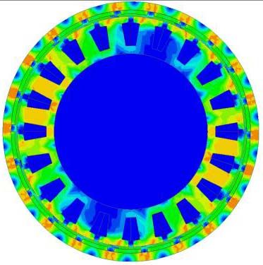
8104605                                                                                    IEEE TRANSACTIONS ON MAGNETICS, VOL. 57, NO. 6, JUNE 2021

                                                                                   Combining (1) and (2), the vth harmonic of the total MMF
                                                                                can be then expressed as

                                                                                      5k N I         φ ∓ vδ            φ               δ
                                                                                 fv =        ·2·cos           cos ωt −      −v θ −         .
                                                                                       πv              2                2              2
                                                                                                                                          (3)
                                                                                  According to (3), a distribution factor of the vth harmonic
                                                                                of MMF is defined in the following equation:

                                                                                                               φ ∓ vδ
                                                                                                   kv = cos             .                 (4)
                                                                                                                 2
                                                                                   The distribution factor of working harmonic can be designed
                                                                                to be 1, i.e., k11 = 1, and the ones of the other parasite
                                                                                harmonics can be selectively eliminated by designing kv .
                                                                                In this article, the first harmonic is first chosen to eliminate,
                                                                                i.e., k1 = 0, and the following relationship can be obtained:
                                                                                                φ − 11δ = 2kπ, with k11 = 1                           (5)
                                                                                                  φ − δ = (2k + 1)π, with k1 = 0.                     (6)
                                                                                   Since the shifted mechanical angle δ should be integral
                                                                                multiple of the slot angle (360◦ /20 = 18◦ ), the optimal angle
                                                                                δoptim is equal to 126◦, i.e., the sub-winding 2 is shifted seven
                                                                                slots compared to the sub-winding 1. In this case, the phase
                                                                                difference of the currents between these two sub-windings is
                                                                                φoptim = −54◦ , i.e., the injected current in sub-winding A2 is
                                                                                lagged 54◦ to the sub-winding A1.
                                                                                   In the case of the elimination of the ninth harmonic,
                                                                                the relationship in (7) should be respected
Fig. 1. 5-phase/20-slots/22-poles conventional winding. (a) Conventional
layout. (b) MMF harmonics [20].                                                                 φ − δ = (2k + 1)π, with k9 = 0.                       (7)
  The MMF of this winding topology is analyzed using                               However, the obtained angle δ from (5) and (7) cannot
winding function theory and shown in Fig. 1(b). It can be seen                  be achieved practically due to the condition of the integral
that the amplitude of the sub- and sup-harmonics are important                  multiple of the slot angle.
compared to the working harmonic (11th). These harmonics                           The proposed new winding configuration is shown
of MMF rotate in the air gap with different speeds inducing                     in Fig. 2(a), which consists of two sub-winding groups: A1 and
eddy-currents and causing losses not only on the stator but also                A2 and shifted by seven slots in the anti-clockwise direction.
on the permanent magnets (PMs) on the rotor, local saturation
and torque ripple, etc., which are expected to be as small as                   C. Supply Strategy of the New Winding
possible.                                                                         The phase difference of the injected currents between the
                                                                                two sub-windings can be obtained by using two five-leg
B. Proposal of New Layout of 20-Slot/ 22-Pole Winding                           voltage source inverter (VSI) inverter but also in the precise
   To eliminate or reduce the parasitic harmonics, the conven-                  case by achieving a star and pentagon connection between
tional winding configuration of each phase can be split into                    the windings as shown in Fig. 2(b). In a five-phase machine
two sub-windings A1 and A2 as shown in Fig. 1(a), and each                      supplied in steady-state operation, the shift angle between two
sub-winding consists of two coils. Considering the injection of                 successive voltages is effectively (180◦ − 360/5)/2 = 54◦ .
fundamental current, the vth MMF harmonic of sub-winding                        To keep the balance MMF distribution between these  √ two sub-
A1 is expressed as                                                              windings, the number of turns of A1 is equal to ( 5/2) times
                          5kw N I                                               of the one of A2. Meanwhile, the section of the conductor
                  f 1v =          cos(ωt ∓ vθ )             (1)                 should be also adjusted in the same ratio to have the same
                            πv
                                                                                current density.
where kw is the winding factor, N is the effective number
of turns of each coil around tooth, I is the rms value of
the current, ω is the angular velocity, θ is the initial angle,                 D. Winding Factors and MMF Analysis
the harmonics rotating in the same direction as the working                        For the new winding layout, the winding distribution coef-
harmonic as are with “−,” and the reverses are with “+.”                        ficient kd = 1 and a short-pitch coefficient kp = 0.9877, and
   Now the new stator shift technique is applied to the con-                    the winding factor is 0.988 instead of 0.9755 for the initial
ventional configuration. Supposing that the sub-winding A2 is                   layout. Hence, the higher flux linkage and the higher torque
shifted by a mechanical angle δ, and the injected current is                    density can be obtained with the new layout.
shifted by an electrical angle φ, the vth MMF harmonic of                          The main advantage of the new winding configuration is the
the sub-winding 2 can be expressed as                                           elimination of selected space harmonics of MMF, while the
                   5k N I                                                       short-end characteristic of FSCW is kept. Using the theory of
           f 2v =          cos[(ωt − φ) ∓ v(θ − δ)].        (2)
                     πv                                                         winding functions, Fig. 3 shows the comparison of the MMF

          Authorized licensed use limited to: UNIVERSITE DE LILLE. Downloaded on July 30,2021 at 16:22:02 UTC from IEEE Xplore. Restrictions apply.
ZHAO et al.: NOVEL FIVE-PHASE FSCW WITH LOW SPACE HARMONIC CONTENTS                                                                                  8104605

Fig. 2. 5-phase/20-slots/22-poles new winding. (a) New winding layout.         Fig. 3.  Comparison of MMF waves and harmonics. (a) MMF wave.
(b) Supply strategy.                                                           (b) MMF harmonics.

                              TABLE I
            M AIN S PECIFICATIONS OF THE T WO M ACHINES

                                                                               Fig. 4.   Flux line distribution with the new winding layout.

                                                                               B. Comparison of Winding-Produced Air-Gap
                                                                               Flux Density and Spectrum
wave and the harmonic spectrum between the two winding                            Fig. 4 shows the winding flux line distribution of the
configurations. It can be seen that the first sub-space harmonic               proposed machine. To remove the interference of the rotor
of the new winding is eliminated, the 11th one is slightly                     magnetic field on the MMF of the windings, the PMs on the
increased, and the total harmonic distortion (THD) is reduced                  rotor are considered as laminated iron.
by 2.2%. The method has been presented for a particular                           The flux density of the two machines under no-load is
five-phase machine but it can be used for other multiphase                     shown in Fig. 5. Only one flux density is shown due to the
machines.                                                                      two are the same because the two machines have a similar
                                                                               rotor except for coil turns.
       III. P ERFORMANCE E VALUATION U SING FEM                                   The MMF harmonic spectrum can be verified by analyzing
                                                                               the winding produced air-gap flux density [19]. The waveforms
A. Machine Design                                                              and the harmonic spectrum of the two configurations are
  To verify the previous analysis, the 5-phase/20-slot/22-pole                 compared in Fig. 6. It can be seen that the first sub-order space
machines with both winding layouts are designed and analyzed                   harmonic is eliminated and the THD is improved by 2.1%.
using FEM. Table I presents the main specifications of the                     Hence, similar results are obtained compared to the ones
machine.                                                                       obtained by winding function theory in Section II-C.

         Authorized licensed use limited to: UNIVERSITE DE LILLE. Downloaded on July 30,2021 at 16:22:02 UTC from IEEE Xplore. Restrictions apply.
8104605                                                                                    IEEE TRANSACTIONS ON MAGNETICS, VOL. 57, NO. 6, JUNE 2021

Fig. 5.   Flux density of two machines under un-load.

                                                                                Fig. 7. Back-EMFs at 600 r/min. (a) Comparison of the back EMF of
                                                                                two machines under no-load. √
                                                                                                            (b) Comparison of the back EMF of two sub-
                                                                                windings under no-load with 5/2 ratio.

Fig. 6. Air gap flux density waves and harmonics without PMs. (a) MMF
wave. (b) MMF harmonics.
                                                                                Fig. 8.   PM loss at 600 and 2100 r/min.

C. Back Electromagnetic Force
   The FEM predicted back electromagnetic forces (EMFs) of
the conventional and the proposed new windings are shown
in Fig. 7(a). It can be seen that the same value of back EMF
is obtained for both configurations (53.14 and 53.08 V for the
conventional and the proposed new windings, respectively),
which can avoid the disadvantage of the conventional stator
shift technique. The back-EMFs of the two sub-windings of the
new winding are shown in Fig. 7(b). The different values are
obtained due to the different number of turns, which can keep
the balance MMF distribution between the two sub-windings
with the current supply strategy shown in Fig. 2(b).                            Fig. 9.   Comparison of efficiency.

D. Comparison of PM Loss and Efficiency                                         MMF harmonics, which shows the effectiveness of the new
  The PM losses of the two machines at rated speed                              method for winding design and also the advantages of the
(600 r/min) and 2100 r/min speed are calculated, respectively,                  new structure of the winding.
and shown in Fig. 8. It can be seen that there are less                           Fig. 9 shows the efficiency of the two machines at rated
PM losses for the proposed winding due to the less parasite                     speed (600 r/min) and 2100 r/min speed, under the same

          Authorized licensed use limited to: UNIVERSITE DE LILLE. Downloaded on July 30,2021 at 16:22:02 UTC from IEEE Xplore. Restrictions apply.
ZHAO et al.: NOVEL FIVE-PHASE FSCW WITH LOW SPACE HARMONIC CONTENTS 8104605
R EFERENCES
[1] A. M. El-Refaie, “Fractional-slot concentrated-windings synchronous
permanent magnet machines: Opportunities and challenges,” IEEE
Trans. Ind. Electron., vol. 57, no. 1, pp. 107–121, Jan. 2010.
[2] J. Gong, H. Zahr, E. Semail, M. Trabelsi, B. Aslan, and F. Scuiller,
“Design considerations of five-phase machine with double p/3p polarity,”
IEEE Trans. Energy Convers., vol. 34, no. 1, pp. 12–24, Mar. 2019.
[3] N. Bianchi, S. Bolognani, M. D. Pre, and G. Grezzani, “Design
considerations for fractional-slot winding configurations of synchronous
machines,” IEEE Trans. Ind. Appl., vol. 42, no. 4, pp. 997–1006,
Jul. 2006.
[4] B. Aslan, E. Semail, J. Korecki, and J. Legranger, “Slot/pole combina-
tions choice for concentrated multiphase machines dedicated to mild-
hybrid applications,” in Proc. 37th Annu. Conf. IEEE Ind. Electron.
Soc. (IECON), Vienna, Austria, Nov. 2011, pp. 3698–3703.
Fig. 10. Comparison of electromagnetic torque. [5] B. Aslan, E. Semail, and J. Legranger, “General analytical model of
magnet average eddy-current volume losses for comparison of multi-
phase PM machines with concentrated winding,” IEEE Trans. Energy
Convers., vol. 29, no. 1, pp. 72–83, Mar. 2014.
[6] G. Dajaku, S. Spas, and D. Gerling, “Advanced optimization methods
for fractional slot concentrated windings,” Electr. Eng., vol. 101, no. 1,
pp. 103–120, Apr. 2019.
[7] P. B. Reddy, K.-K. Huh, and A. M. EL-Refaie, “Generalized approach
of stator shifting in interior permanent-magnet machines equipped
with fractional-slot concentrated windings,” IEEE Trans. Ind. Electron.,
vol. 61, no. 9, pp. 5035–5046, Sep. 2014.
[8] S. Zhu, T. Cox, Z. Xu, and C. Gerada, “Novel 24-slots 14-poles
fractional-slot concentrated winding topology with low-space harmonics
for electrical machine,” J. Eng., vol. 2019, no. 17, pp. 3784–3788,
Jun. 2019.
[9] A. S. Abdel-Khalik, S. Ahmed, and A. M. Massoud, “A six-phase
24-slot/10-pole permanent-magnet machine with low space harmonics
for electric vehicle applications,” IEEE Trans. Magn., vol. 52, no. 6,
Fig. 11. Comparison of torque–speed curves. pp. 1–10, Jun. 2016.
[10] V. I. Patel, J. Wang, W. Wang, and X. Chen, “Six-phase fractional-
slot-per-pole-per-phase permanent-magnet machines with low space
injected current, respectively. It can be seen that the efficiency harmonics for electric vehicle application,” IEEE Trans. Ind. Appl.,
in both speeds has been improved. At the 2100 r/min speed, vol. 50, no. 4, pp. 2554–2563, Jul. 2014.
the efficiency has increased from 85.3% to 86.5%. [11] K. Wang, Z. Q. Zhu, and G. Ombach, “Synthesis of high performance
fractional-slot permanent-magnet machines with coil-pitch of two slot-
pitches,” IEEE Trans. Energy Convers., vol. 29, no. 3, pp. 758–770,
E. Electromagnetic Torque Characteristic Sep. 2014.
Fig. 10 shows the electromagnetic torque characteristics [12] P. Zheng, F. Wu, Y. Lei, Y. Sui, and B. Yu, “Investigation of
with the same current density injection J = 5 A/mm2 . It can a novel 24-slot/14-pole six-phase fault-tolerant modular permanent-
magnet in-wheel motor for electric vehicles,” Energies, vol. 6, no. 10,
be noted that the average torque is increased by 1% and the pp. 4980–5002, Sep. 2013.
torque ripple is reduced by 60% with the new winding layout. [13] G. Dajaku and D. Gerling, “A novel 24-slots/10-poles winding topology
Fig. 11 shows the torque–speed curves under the same for electric machines,” in Proc. IEEE Int. Electr. Mach. Drives Conf.
condition. It can be noted that with the new winding layout, the (IEMDC), Niagara Falls, ON, Canada, May 2011, pp. 65–70.
[14] N. Bekka, M. H. EI Zaim, N. Bernard, and D. Trichet, “A novel
average torque is slightly increased during the entire operating methodology for optimal design of fractional slot with concentrated
range. windings,” IEEE Trans. Energy Convers., vol. 31, no. 3, pp. 1153–1160,
Sep. 2016.
[15] N. Tang and I. P. Brown, “A systematic approach for developing electric
IV. C ONCLUSION machine windings with suppressed MMF space harmonics,” Electr.
In this article, a novel 5-phase/20-slot/22-pole winding Power Compon. Syst., vol. 45, no. 20, pp. 2327–2338, Dec. 2017.
topology is proposed by a stator shift technique combined [16] N. Tang and I. P. Brown, “Framework and solution techniques for
suppressing electric machine winding MMF space harmonics by varying
with a star/pentagon winding connection. Compared to the slot distribution and coil turns,” IEEE Trans. Magn., vol. 54, no. 5,
conventional configuration, the first harmonic of MMF in the pp. 1–12, May 2018.
new winding is eliminated. Moreover, the non-overlapping [17] M. V. Cistelecan, F. J. T. E. Ferreira, and M. Popescu, “Three phase
characteristics of FSCW are kept. The winding factor of tooth-concentrated multiple-layer fractional windings with low space
harmonic content,” in Proc. IEEE Energy Convers. Congr. Expo.,
new winding is improved, and the THD of MMF is reduced Sep. 2010, pp. 1399–1405.
by 2.1%. The output torque is increased by 1%, and the [18] W. Zhao, J. Zheng, J. Ji, S. Zhu, and M. Kang, “Star and delta hybrid
torque ripple is reduced by 60%. The FEM results proved connection of a FSCW PM machine for low space harmonics,” IEEE
the effectiveness of the proposal. Trans. Ind. Electron., vol. 65, no. 12, pp. 9266–9279, Dec. 2018.
[19] Y. Sui, P. Zheng, F. Wu, B. Yu, P. Wang, and J. Zhang, “Research
on a 20-slot/22-pole five-phase fault-tolerant PMSM used for four-
ACKNOWLEDGMENT wheel-drive electric vehicles,” Energies, vol. 7, no. 3, pp. 1265–1287,
Mar. 2014.
This work was supported by the Natural Science Foundation [20] J. Marault, F. Gillon, M. Hecquet, and A. Tounzi, “Optimization of the
of Shandong Province of China through the Project under MMF spatial harmonic content to design electrical machine winding,”
Grant ZR2020ME207. Int. J. Appl. Electromagn. Mech., vol. 64, pp. S99–S114, Jan. 2021.
Authorized licensed use limited to: UNIVERSITE DE LILLE. Downloaded on July 30,2021 at 16:22:02 UTC from IEEE Xplore. Restrictions apply.You can also read