Interactive Hairstyle Modeling Using a Sketching Interface
←
→
Page content transcription
If your browser does not render page correctly, please read the page content below
Interactive Hairstyle Modeling
                         Using a Sketching Interface

           Xiaoyang Mao1 , Kouichi Kashio 2 , Hiroyuki Kato1 and Atsumi Imamiya1
    1
        Department of Computer and Media Engineering, Yamanashi University, 4-3-11 Takeda,
                              Kofu, Yamanashi 400-0016, Japan
                  {Mao,kato,imamiya}@hci.media.yamanashi.ac.jp
                       2
                         Sony Corporation, Mobile Network Company, Japan.
                           Hirokazu.Kashio@dvpj.sony.co.jp

         Abstract. Modeling and rendering human hair remains to be one of the most
         challenging computer graphics problems. This paper presents a new interactive
         hair modeling system featured with a user-friendly sketching interface. With the
         sketching interface, any user, even a first time user, can create a hair model of
         his/her desired style just in a few minutes simply by interactively drawing
         several strokes illustrating the global and local features of the hairstyle. The
         result of the system is a generic geometry-based representation of hair which
         can be post manipulated and rendered with most existing systems.

1   Introduction

   Needless to say, hair is one of the most important visual elements featuring a
human character. A person can look having a completely different expression just by
changing his/her hairstyle. To synthesis realistic hair images, researches have been
challenged by many difficult problems inherently caused by the special properties of
human hair, such as the huge number of hair strands, the extremely small diameter of
individual strand compared with an image pixel, and the complex interaction of light
and shadow among strands. In the past decade, a number of novel techniques have
been developed for successfully shading hair strands and eliminating alising
artifacts[1~6]. In this paper, we presents a new system for allowing users to
interactively create 3D hair models of their desired styles. Modeling different 3D
hairstyles is even a more difficult problem as the huge variation of hairstyles is
determined by extremely comple x interactions of many factors. These factors include
gravity, static charges, strand-to-strand and strand-to-head interaction, styling tools
such as hair pins, hair bands and mousse. Recently, several papers have been
published addressing this hairstyle modeling issue[7~11]. A common approach used
in those systems is the representation of the cluster of hair strands. Because of the
cosmetics and static electricity, nearby hairs tend to form clusters. Use a cluster
instead of a single strand as the smallest unit of shape control makes it possible for
allowing users to interactively design their desired hairstyles. The trigonal prism wisp
model presented by Chen et al.[7] represents each cluster(wisp) with a trigonal prism
and the hair strands within a cluster is modeled by the distribution map defined on the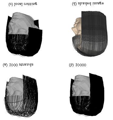
cross-sections of the prism. An editing tool is provided for allowing users to
interactively position clusters on the scalp and change the shapes of clusters. The
hierarchical cluster model and V-hairStudio developed by Xu et al.[8,10] uses a
generalized cylinder to represent a hair cluster. Each cross-section of a cylinder is
associated with a density distribution of the hair strands inside the cluster and the
output of the system is a volume density representation of hair. Hairstyles are created
by interactively changing the shape of the center lines of cylinders. Other researchers
explored the possibility of using vector fields for hairstyle modeling[9,11]. Yu
succeeded in creating very realistic and complicated hairstyles by modeling the flow
and curliness of hair using procedurally defined vector fields[11].
   Although most existing hair modeling systems do provide users with some kinds of
interactive design tools, the interfaces of those tools, however, are not user friendly. It
can be very difficult and tedious for users to construct a hairstyle by adjusting the
shape of each hair cluster. For example, it takes about one to two hours for a user
familiar with the system to create a typical hairstyle with the hierarchical cluster
model[8]. The largest advantage of our new hairstyle modeling system is its user-
friendly sketching interface. With this interface, any user, even a first time user, can
create a hair model of his/her desired style just in a few minutes. Our technique is
based on the consideration that when we look at someone’s hairstyle, we pay more
attention to its overall design instead of the detailed shape of individual hair strand or
cluster. Therefore, instead of asking a user to put strands or clusters together to build
up the whole hairstyle, we ask a user to start with specifying the silhouette of the
target hairstyle. Based on the silhouette, the system automatically generates a
hairstyle and then the user is allowed to locally modify it to obtain the ideal one. In
our system, the hairstyle silhouette and all other operations are specified interactively
with 2D mouse or tablet as freeform strokes.
   The remaining part of the paper is organized as follows: Section 2 gives the
overview of the system. Section 3 describes how to specify the silhouette and
partition lines of hair and also the area for growing hair. Section 4 describes the
algorithm for defining the surface boundary of a hairstyle and Section 5 introduces the
rule for growing hair. Section 6 demonstrates some hairstyles generated with our
system. Finally, in Section 7, we conclude the paper by showing the future research
directions.

2   Overview

A typical hairstyle modeling process in our system consists of the following 6 steps:
   1. Loading 3D head model to the view window
   2. Specifying the area to grow hair
   3. Specifying the partition line
   4. Specifying the silhouette of the hairstyle
   5. Growing hair
   6. Locally modifying the hairstyle
After the 3D head model is displayed on the view window, a user is asked to
interactively draw the boundary of the region to grow hair and also the partition line
of hair. Fig. 1(a) is an example of such a user-drawn boundary and a partition line.
Next, the user is asked to draw a stroke representing the silhouette of the target
hairstyle(Fig. 1(b)). Based on the silhouette line, the system automatically generates a
surface representing the boundary of the hairstyle(Fig. 2(b)). We call this surface
silhouette surface hereafter. 3D hair model is then obtained by growing hair strands to
fill in the space between the silhouette surface and the surface pf the scalp(Fig. 1(d)).
Finally, the user is allowed to locally modify the hairstyle using operations such as
cutting, combing and perm. Currently, only the cutting operation is supported and
other local modification operations will be available in the near future. We will
discuss the detail of each step in the following sections.

Fig. 1. A typical process of hairstyle modeling. (a) A user draws the strokes specifying the
boundary of the region to grow hair and the partition line of hair. (b) The user also draw the
silhouette line of the target hairstyle. (c) The system automatically creates the silhouette surface
of the hairstyle. (d) The system grows hair strands to fill in the space between the silhouette
surface and the surface of the scalp.
3   Specifying the Region to Grow Hair, the Partition Line and the
    Silhouette Line

The boundary of the region to grow hair, the partition line of hair and the silhouette of
a hairstyle are all specified through drawing freeform strokes either using a 2D mouse
or a tablet. The strokes representing the boundary of the region to grow hair and the
partition line are drawn on the displayed 3D head model directly. A user can rotate
the head model to any angle suitable for the drawing task. As shown in Fig. 2, the
drawn strokes are projected onto the head model to get the 3D representation of the
boundary and the partition line.

      Fig. 2. Strokes drawn on the view window are projected onto the 3D head model.

   To find the region inside the boundary, we need a flattened map of the scalp. A
possible approach is to parameterize the scalp using a 2D polar coordinate
system[11]. Here we use projection to map the boundary and the scalps onto a 2D
plane. We virtually place a plane on the top of the head and project the boundary as
well as all the vertices of the head model onto the plane. By carefully selecting the
position of the projection center, we can preserve the relative 3D position of vertices
respective to the boundary on the 2D plane. Currently, our system only accepts
partition line located at the center of the top of the scalp and we assume the resulting
hairstyle is symmetric about the partition line. Therefore users are asked to draw only
the right half silhouette of a hairstyle.

4   Silhouette Surface

Based on the silhouette line, the system automatically creates the silhouette surface of
the hairstyle. The shape of the silhouette surface should be decided by taking into
consideration both the shape of silhouette line and the shape of scalp. To do this, as
shown in Fig. 3, we first obtain a set of evenly spaced cross-sections of the head
model along the Z-axis and create a silhouette line for each cross-section by
deforming the input silhouette line to match the shape of the contour line of the cross-
section. The cross-section starts at the front end point of the partition line and ends at
the back end point. Interpolating the silhouette lines for all cross-sections gives the
silhouette surface of the side area of the hairstyle. The cross-section with the largest
width in X-direction is called basic cross-section. The user drawn silhouette line is
first projected onto the plane of the basic cross-section to obtain the silhouette line for
the basic cross-section. We call this silhouette line basic silhouette line. To create the
silhouette line for other cross-sections, we calculate the height and width difference of
the cross-section and the basic cross-section. Then the silhouette line is obtained by
first translating the basic silhouette line in Y-direction the amount of the height
difference followed by a shrinking in X-direction with the amount of the width
difference.
Fig. 3. Cross-sections and silhouette lines.
To generate the silhouette surface for the forehead and the back area, we
approximately assume hair strands grow radially from the front and back end points
of the partition line. As shown in Fig. 4, to obtain the silhouette lines for the front
area, we sweep the silhouette line for the cross-section at the front end point of the
partition line through the forehead while keeping the distance from the silhouette lines
to the forehead to be constant. The silhouette lines for the back area is created in the
same way by sweeping the silhouette line for the cross-section at the back end point
of partition line. Fig. 1(c) is the silhouette surface generated with the described
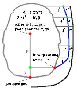
method based on the user drawn silhouette line shown in Fig. 1(b).Fig. 4. Creating silhouette lines for the forehead area. 5 Growing Hair After the surface silhouette of a hairstyle is generated, the system automatically grows hair to fill in the space between the silhouette surface and the surface of the scalp. There are mainly two existing approaches to represent hair. One is called explicit model and the other is called volume density model. The explicit model represents individual hair strand with some geometrical object, such as a connection of cylinders, a curved polyline or a connected segments of triangular prism[1,2,4,5,11] while the volume density model represents the entire hair style macroscopically as a 3D distribution function of hair density[3,8,10]. Our system chooses the explicit model and use curved polyline to represent each hair strand. We choose the explicit model because most existing hair modeling and rendering systems support this model rather than the volume density model, and therefore the resulting hair models of our system can be easily post manipulated and rendered with those systems. Usually at least 10000 to 15000 hair strands are required to generate a realistic hair image. On the other hand, the number of hair strands used in the modeling stage should be as small as possible so as to provide real time feedbacks to their operations. To fulfill these two requirements simultaneously, we allow users to specify the number of hair strands by themselves. As we will demonstrate in the next section, 1000 strands seems to be enough for the purpose of previewing and with this number users can get a real time feedback of their operations on a standard PC. We also support a trigonal prism representation for the final hair model. After the number of hair strands is specified, the positions for growing these hair strands are decided by uniformly distributing the this number of points over the scalp within the region to grow hair. Each hair strand is generated following the rule that it passes through the space in between the silhouette surface and the surface of the scalp. The higher its growing position is, the closer it is from the silhouette surface. This rule is depicted in Fig. 5. We first generate the vertical line segment between the top of the scalp and the lowest position of hair growing region. Then we bisect the
segment with the position to grow the strands to obtain two segments of length a and
b, respectively. The polyline of the hair strand is then constituted by the vertices
which bisect the distance between the silhouette surface and scalp surface by the
ration of a/b.
Fig. 5. Rule for growing a hair strand.
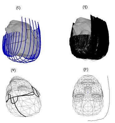
6 Results
We have implemented our interactive hairstyle modeling system on Windows
environment with Visual C++ and OpenGL graphics library. Fig. 6 shows several
images of the hairstyle generated with the stroke inputs shown in Fig. 1. Fig. 6(a) and
(b) are the images when 1000 and 10000 hair strands are used, respectively. Fig. 6(c)
is an image generated by locally applying a cutting operation to the hair model shown
in Fig. 6(b). Cutting operation is specified by drawing the freeform stroke of the
cutting line directly on the 3D rendered hair model. The Fig. 6(d) is image rendered
with D StudioMax1. Each hair strand is represented as a trigonal prism in this case.
Times required for rendering images of 1000 and 10000 hair strands on a Pentium
machine with two Xeon 933 MHz CPU are about 0.4 and 9 seconds, respectively. Fig.
7 and 8 demonstrate that how curly and wavy hairstyle can also be easily created
simply by drawing a curly or wavy silhouette line.
1 3D StudioMax is the trade mark of Autodesk, Inc.Fig. 6. Images generated with the stroke inputs shown in Fig. 1. Fig. 7.A curly hairstyle generated with our system. Left: user specified silhouette. Right: resulting hairstyle.
Fig.8. A wavy hairstyle generated with our system. Left: user specified silhouette. Right:
resulting hairstyle.

7   Concluding Remarks

We have presented an interactive hairstyle modeling system featured with a sketch
interface. The idea of using sketching interface is also inspired by Teddy, a successful
sketching interface for 3D freeform design[12]. As we mentioned in Section 1, the
variation of hairstyles is determined by extremely complex interactions of many
factors, such as gravity, strand-to-strand and strand-to-head interaction and styling
tools. A faithful physical simulation of all those factors can be very difficult and time
consuming. In many applications, however, an expressive presentation of
personalized features of hairstyles is of most important. Our sketching interface
provides an easy to use expressive design tool to those applications. For example, as
the potential applications, our system can be used to smooth the communication
between a customer and a stylist at hair salons and also used for in house CG creation
for visually present the a designer’s requirements to a professional CG modeling
specialist.
   The results presented in this paper are just the very initial results of our prototype
system and the variation of hairstyles is limited currently. We are now implementing
other local modification operations such as combing and perm. To make the hair
image look more realistic, we need to add some randomness to the positions and
shapes of hair strands generated following the rule introduced in Section ?. We are
now implementing a method which groups hair strands near by into clusters and adds
randomness to the shape of each hair cluster. Also we need some special
consideration for generating short cut hairstyles.
References

1. LeBlanc A. M., Turner R. and Thalmann D.: Rendering Hair using Pixel Blending and
   Shadow Buffers, The Journal of Visualization and Computer Animation, Vol. 2, (1991) 92-
   97.
2. Rosenblum R.. R., Carlson W. E. and Tripp III E.: Simulating the Structure and Dynamics
   of Human Hair: Modeling, Rendering and Animation, The Journal of Visualization and
   Computer Animation, Vol. 2, (1991)141-148.
3. Kajiya T. and Kay T.L.: Rendering Fur with Three Dimensional Textures, Computer
   Graphics, Vol.23, No.3, (1989) 271-280.
4. Watanabe Y. and Suenaga Y.: A Trigonal Prism-Based Method for Hair Image Generation”,
   IEEE Computer Graphics & Applications, (1992) 47-53
5. Anjyo K., Usami Y. and Kurihara T.:A Simple Method for Extracting the Natural Beauty of
   Hair, Computer Graphics, Vol.26, No.2, (1992) 111-120.
6. Magnenat Thalmann N., Kurihara T., Thalmann D.: An Integrated System for Modeling,
   Animating, and Rendering Hair., Proceedings of EUROGRAPHICS '93, 211-221.
7. Chen L.H., Saeyor S., Dohi H. and Ishizuka M.: A System of 3D Hair Style Synthesis based
   on the Wisp Model, Visual Computer, Vol. 15, (1999) 159-170.
8. Yang, Xue Dong, Tao Wang Zhan Xu, and Hu Qiang: Hierarchical Cluster Hair Model,
   Proceedings of the IASTED International Conference on Computer Graphics and Imaging,
   (2000) 75-81.
9. Hadap S. and Magnenat-Thalmann N.: Interactive Hair Styler Based on Fluid Flow,
   Proceedings of Eurographics Workshop on Computer Animation and Simulation '2000.
10.Xu Z. and Yang X. D: V-HairStudio: An Interactive Tool for Hair Design, IEEE Computer
   Graphics & Applications, Vol. 21, No. 3 (2001)36-43.
11.Yu Yizhou: Modeling Realistic Virtual Hairstyles, Proceedings of Pacific Graphics’01,
   (2001) 295-304.
12.Igarashi T., Matsuoka S., Tanaka H.: Teddy: A Sketching Interface for 3D Freefrom
   Design, ACM SIGGRAPH 99, 409-416.
You can also read