Using the PLUTO language on functional tests of a Brazilian Satellite's On-Board Data Handling Computer
←
→
Page content transcription
If your browser does not render page correctly, please read the page content below
Using the PLUTO language on functional tests of a Brazilian
       Satellite’s On-Board Data Handling Computer

                             T. D. Pereira1, M. G. V. Ferreira2 and F. N. Kucinskis3
                Brazilian National Institute for Space Research, São José dos Campos, São Paulo

            The testing of the functionalities of an On-Board Data Handling Computer (OBDH) is a
        highly complex task, especially when a standard language, appropriate for procedures
        execution, is not available. To reduce the complexity degree, the European Cooperation for
        Space Standardization (ECSS) specified a language that can be used to standardize the test
        procedures, called Procedure Language for Users in Test and Operations (PLUTO). The use
        of such language implies some resources that are considered essential for procedures
        execution. One of them is the existence of a system data model, called Space System Model
        (SSM), also specified by ECSS. The Brazilian Institute for Space Research (INPE) wants to
        use this language to standardize the creation and execution of its test procedures, but does
        not have all the needed resources yet. To achieve this goal, a computational environment is
        being developed at INPE through the following steps: definition of an architecture that
        contains the key resources to execute PLUTO procedures; creation of procedures in the
        language syntax; modeling of the system under test through SSM specifications; and the
        development of common communication interfaces between the model and the system to be
        tested. Functional requirements of an OBDH were selected to be used on the construction of
        test procedures. These requirements are related to attitude and orbit control functionalities
        executed according to input data acquired by simulation result of a sun sensor. This paper
        describes the architecture defined to the development of this environment.

                                               Nomenclature

ACDH      =   Attitude Control and Data-Handling
AIT       =   Assembly, Integration and Test
DSV       =   Domain-Specific View
ECSS      =   European Cooperation for Space Standardization
EGSE      =   Electrical Ground Support Equipment
ESA       =   European Space Agency
IDE       =   Integrated Development Environment
INPE      =   Brazilian National Institute for Space Research
OBDH      =   On-Board Data Handling
PLUTO     =   Procedures Language for Users in Test and Operations
SIA       =   Inertial Systems for Aerospace Application
SSM       =   Space System Model
STEPS     =   Spacecraft Test Procedures System
SUT       =   System Under Test
SVDA      =   Sun Vector’s Determination Algorithm

1
  Master’s student, INPE’s Space Engineering and Technology Course, thiago@dea.inpe.br.
2
  Technologist, INPE’s Satellite Control Center, mauricio@ccs.inpe.br.
3
  Technologist, INPE’s Aerospace Electronics Division, fabricio@dea.inpe.br.
                                                         1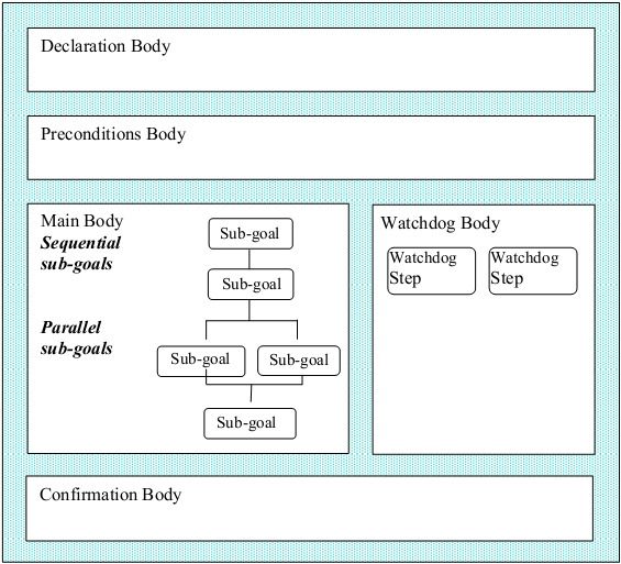
I. Introduction

I  N order to validate the functionalities of a satellite, sets of test procedures are executed in different abstraction
   levels during the development phases of the space system. It is common to create test procedures using different
languages, at different development and integration stages that do the same (or almost the same) thing. To avoid
such “re-creation” effort, the solution is the standardization of the procedures using only one language. Once
standardized, a single procedure could be applied in different scenarios.
    The Brazilian National Institute for Space Research (INPE) lacks such standardization. Each Electrical Ground
Support Equipment (EGSE) developed to test the subsystems and equipments of INPE’s satellites has its own test
procedures execution system that implements “ad-hoc” technologies or processes. This generates high costs that
could be reduced if a single standard were followed.
    The European Cooperation for Space Standardization (ECSS) defines engineering, product assurance and project
management standards to be applied to space activities. These standards allow a better organization of satellite’s
development processes. One of this standards is the ‘Test and Operations Procedure Language’ that specifies a
language standard called Procedure Language for Users in Test and Operations (PLUTO) 1.
    This language can be used to describe test and operation procedures to be executed in computational
environments. In recent years, the European industry and universities and research institutes are using it in projects
for the ESA’s missions and human resources training 2, 3.
    INPE’s goal is to develop a computational environment that allows test procedures creation and execution with
the PLUTO language. This system was named ‘Spacecraft Test Procedures System’ (STEPS). A STEPS prototype
and its architecture will be shown in this paper. To develop this prototype, a Sun Vector’s Determination Algorithm
(SVDA) was used as a case study. This algorithm is executed by an on-board computer that is being developed
through Inertial Systems for Aerospace Application (SIA) project.

                       II. Our approach to standardize procedures with PLUTO

A. The Procedures Structure and Needs to Use It
    Using this language for test procedures brings a set of advantage for INPE:
    1) Allows the re-use of test procedures at different levels (unit, subsystem and system);
    2) Increases the information exchange between test and operation activities; and
    3) Analyze it for application at satellite’s operation procedures.
                                                                PLUTO language is similar to a high-level
                                                            programming language. Its structure is shown in Figure
                                                            1. Some instructions are optional, except the ‘Main
                                                            Body’ that is composed by steps. The steps can be a
                                                            command or a set of commands, an action request to the
                                                            operator or a call to another procedure.
                                                                The language allows logical conditions construction;
                                                            operator interaction during execution; loop routines;
                                                            arithmetic operations with various engineering data; and
                                                            scheduling of execution.
                                                                In a ‘Declaration Body’ the user can declare global
                                                            variables or events that can occur in the System Under
                                                            Test (SUT) during the procedure execution. The
                                                            ‘Preconditions Body’ allows the description of conditions
                                                            to start the procedure execution. These conditions can be:
                                                            wait some time, wait until a condition or set of conditions
                                                            become true.
                                                                The ‘Watchdog Body’ purpose is to detect events at
                                                 1          system level, for example, anomalies on some equipment.
  Figure 1. Structure of a PLUTO procedure .
                                                            On a given anomaly detection, the watchdog interrupts
                                                            the procedure execution.
    The instructions written in the ‘Confirmation Body’ verify the equipment under test or operation to make sure
that the ‘Main Body’ steps were executed correctly. As PLUTO is an interpreted language, it needs an interpreter to
execute its instructions set in conformance with the ECSS standard that specifies it. INPE aims to develop a
PLUTO language interpreter for applying it in test activity during the development of its equipments and

                                                           2
subsystems, and also at AIT activities. Having an interpreter, PLUTO test procedures start to be a deliverable item,
together with contracted subsystems and equipments.

B. The Space System Model
    The use of the PLUTO language requires a SUT data model. ECSS has proposed a data model for the entire
space system in its ‘Ground Systems and Operations’ standard.
                                                                           The data model structure must be
                                                                       hierarchical in order to represent the real
                                                                       functional decomposition of the system. This
                                                                       structure is called Space System Model
                                                                       (SSM) 4.
                                                                           The SSM is composed by different data
                                                                       types which are identified as objects. The
                                                                       object types are classified as System Element;
                                                                       Activity, that can be executed by it System
                                                                       Elements; Report Data that reflects the
                                                                       System Element state; and Events that can be
                                                                       handled for its control and monitoring.
                                                                           Figure 2 shows a System Element
                                                                       composed by Activities, Report Data and
                                                                       other data that are used for configuration
                                                                       management and requirements control during
                                                                       its life cycle. Any System Element can also
                                                                       comprise other System Elements.
    Figure 2. Object types associated to a System Element 5.               Due to the large amount of information in
                                                                       a SSM, there is the need to extract, for a given
problem, only the required data. In order to do so, ECSS has specified the Domain Specific View (DSV) 4. A DSV is
composed by a subset of the model needed for a given application. This concept can be used during the development
of equipments and subsystems and only the interest data for that application are used into SSM.
    Croce6 applied PLUTO language and SSM concepts in its work. He stated that a PLUTO procedure must
reference a SSM object and, in order to write or execute the procedures the best way is to maintain the SSM
structure between the procedure executor and the SUT. During the execution, the access to the model is
encapsulated. Seymour7 also says that a PLUTO procedure must refer to the SSM to read or write values into its
objects. The data read and write into the model are done by a language interpreter during execution.

                                                          3
III. STEPS Architecture
   From those presented concepts, INPE is developing a computational environment called ‘Spacecraft Test
Procedures System’ (STEPS) to prepare and execute test procedures. Figure 3 shows its components.

   Figure 3. STEPS’s architecture.

    To start procedures execution, the SSM must be loaded in memory in order to be accessed by the language
interpreter accesses its objects. This image of the SUT’s model is called ‘SSM Instance’. This module allocates a
data structure into memory with the same hierarchical characteristics as the SSM specifications. Its basic operation
is to search the model objects through parameter identification. The access to model is done through Get and Set
requests generated by language interpreter and sent to the ‘SSM Instance’.
    A Get request reads an object of type Event or Report Data. A Set request writes data into a SSM object or
requests an execution, if the object is Activity type. If the SSM receives a Get request from ‘PLUTO Interpreter’, it
returns the last acquired value and if it receives a Set request, it interacts with SUT through transmission of
telecommand and telemetry. The communication between ‘SSM Instance’ and ‘SUT’ is done by an interface that
interprets the object purpose and transcribes its purpose into telecommand.
    ‘SSM Instance’ module is composed by the ‘Identify Events’ and ‘External Interfaces’ components. The first can
be used by the user to define customized Events in SUT context. An Event can be the occurrence of conditions that
can be configured by the user into SSM or generated by SUT. The second component allows communication from
procedure interpreter with external equipments. In some cases, a test procedure requires interaction of other
equipment with SUT to achieve the test objectives.
    Once instantiated, the SSM can be accessed by the ‘PLUTO Interpreter’. ‘PLUTO interpreter’ interprets the
procedure steps to execute it and sends Get and Set requests to the instantiated model. This architecture also has
support elements to prepare and monitor the SUT model and PLUTO procedures and to store test results.

                                                         4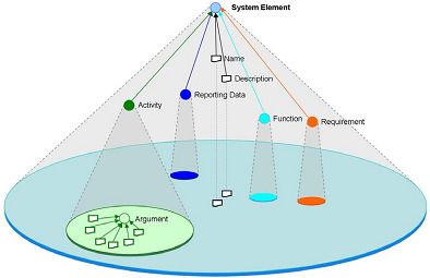
IV. Developing a STEPS Prototype

A. A Case Study for the STEPS Prototype
     The INPE’s On-Board Data Handling team is developing an on-board computer to the SIA’s project orbital
platform. As this on-board computer will execute both On-Board Data Handling and the Attitude Control functions,
it is being called Attitude Control and Data Handling (ACDH) Computer. The ACDH Computer has communication
interfaces with other equipments and subsystems including four solar sensors, each one measuring the intensity of
sunlight on one face of the platform.
     ACDH Computer flight software runs a Sun Vector’s Determination Algorithm (SVDA) to define the satellite
control parameters. It receives measurement values from four solar sensors and determines the current satellite
attitude with respect to the Sun and, if necessary, to perform an attitude maneuver to point the solar panels to it.
Figure 4 illustrates the four solar sensors scenario.

         Sun Vector’s Determination Algorithm Scenario

                                                                         Sun
                                                                        Sensor
                                                                          A

                                                                  Y

                                                                                         Z

                                                         Analog   ACDH Computer
                                     Sunlight    Sun     inputs                                Sun
                                                Sensor                Sun Vector’s            Sensor
                                                  D                    Algorithm                B

                                                                                        X

                                                                          Sun
                                                                         Sensor
                                                                           C

   Figure 4. Case Study (Sun Vector’s Determination Scenario).

    SVDA calculates the X, Y and Z axis from sensors values and release it to satellite attitude control with three-
axis stabilization. To test this case, the EGSE communicates with ACDH Computer through analog and digital
interfaces to send analog values to simulate the solar sensors. The on-board computer receives the EGSE analog
values and uses it as parameters to SVDA execution.
    This case study was created to exercise the STEPS prototype, not being representative of a real attitude
determination scenario.

B. The STEPS Prototype
    From the case study a SSM and a PLUTO procedure to test SVDA were developed. The SSM includes all data
relevant to the SVDA context: four input parameters generated by solar sensors and three output parameters
generated by SVDA. The procedure has instructions to access the objects from model. Figure 5 shows the procedure
created for this case study.

                                                           5
1 procedure Sun_Vector_Determination
2 Declare
3 variable real X_Axis := 0.0 deg;
deg;
4 variable real Y_Axis := 0.0 deg;
deg;
5 variable real Z_Axis := 0.0 deg;
deg;
6 variable real analog_value_out1 := 0.0 Volts;
Volts;
7 variable real analog_value_out2 := 0.0 Volts;
Volts;
8 variable real analog_value_out3 := 0.0 Volts;
Volts;
9 variable real analog_value_out4 := 0.0 Volts;
Volts;
10 end declare
11 preconditions
12 wait until switch_on of ACDH_COMPUTER = true;
13 end preconditions
14 main
15 Simulate Environment Analog_Value_Out_1 of SUN_SENSOR_A of ACDH_SUBSYSTEM of SATELLITE;
;
16 Simulate Environment Analog_Value_Out_2 of SUN_SENSOR_B of ACDH_SUBSYSTEM of SATELLITE;
;
17 Simulate Environment Analog_Value_Out_3 of SUN_SENSOR_C of ACDH_SUBSYSTEM of SATELLITE;
;
18 Simulate Environment Analog_Value_Out_4 of SUN_SENSOR_D of ACDH_SUBSYSTEM of SATELLITE;
;
19 analog_value_out1 := Analog_Value_Out_1 of SUN_SENSOR_A of ACDH_SUBSYSTEM of SATELLITE;
;
20 analog_value_out2 := Analog_Value_Out_2 of SUN_SENSOR_B of ACDH_SUBSYSTEM of SATELLITE;
;
21 analog_value_out3 := Analog_Value_Out_3 of SUN_SENSOR_C of ACDH_SUBSYSTEM of SATELLITE;
;
22 analog_value_out4 := Analog_Value_Out_4 of SUN_SENSOR_D of ACDH_SUBSYSTEM of SATELLITE;
;
23 wait for 0.5 s;
24 X_Axis := Sun_Vector_X_Axis of SUN_VECTOR_ALG of ACDH_COMPUTER of ACDH_SUBSYSTEM of SATELLITE;
;
25 inform user “X axis result: ” X_Axis;
;
26 Y_Axis := Sun_Vector_Y_Axis of SUN_VECTOR_ALG of ACDH_COMPUTER of ACDH_SUBSYSTEM of SATELLITE;
;
27 inform user “Y axis result: ” Y_Axis;
;
28 Z_Axis := Sun_Vector_Z_Axis of SUN_VECTOR_ALG of ACDH_COMPUTER of ACDH_SUBSYSTEM of SATELLITE;
;
29 inform user “Z axis result: ” Z_Axis;
;
30 end main
31 end
Figure 5. PLUTO procedure defined for the case study.
Access to objects from model is done through procedure either for data reading or writing. The procedure
described at Figure 5, has a command called Simulates Environment that is not specified in PLUTO standard. It was
defined due to an expected need regards to the interaction from SUT with other equipments during the tests. At this
work, ADVS depends on interaction between ACDH Computer and solar sensors. When the Simulates Environment
command is interpreted, the PLUTO Interpreter sends a Set request to SSM Instance. Then SSM Instance uses the
communication mechanism that was defined in the External Interfaces to keep communication with these solar
sensors.
Although due to the lack of these solar sensors, a simulator was created to send relevant data to ACDH
Computer. This simulator sends four individual values to be used as input data by ADVS. The usage of this
simulator can be manually or automated by a PLUTO procedure as presented in this work.
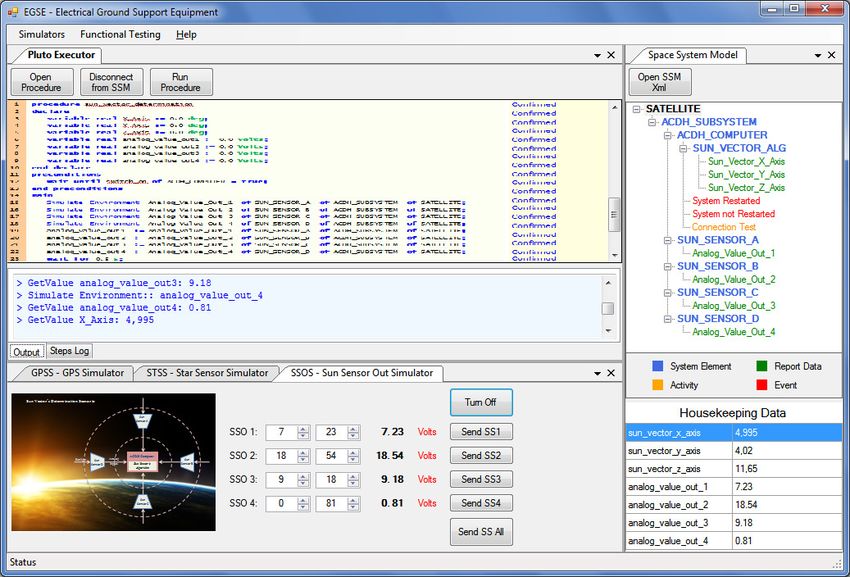
Figure 6 shows the STEPS prototype Graphical User Interface (GUI). This prototype loads the SSM, shows SSM
hierarchical and waits for start of procedure execution. It also affords data visualization through ‘Housekeeping
Data’ area during execution. The procedure and model were described in text format and XML scheme. The
confirmation status of each procedure command is informed as ‘confirmed’, ‘not confirmed’ or ‘aborted’ and each
operation made by interpreter is also informed in the Output Log area.
6Figure 6. STEPS’s Graphical Interface.
V. Conclusions
This work represents a first effort to standardize INPE’s test procedures with PLUTO language. A prototype was
developed having a ‘PLUTO Interpreter’ with routines to execute a procedure and a ‘SSM Instance’ to manage a
model. Both were applied to the presented case study. Communication mechanisms between interpreter and
instanced model were developed to allow its communication with SUT and external equipment. Our goal is to
follow with the STEPS development to create a full ‘PLUTO Interpreter’ and a ‘SSM Manager’ with GUIs to
facilitate the preparation and to monitor the test procedures execution.
Acknowledgements
The authors would like to thank the contribution of Ronaldo Arias INPE’s Technologist and SIA project
member, and also Research and Projects Financing (FINEP-FUNDEP-SIA) for the financial support.
References
1
European Cooperation for Space Standardization (ECSS), “Space Engineering: Test and Operations Procedure Language”,
ECSS-E-ST-70-32C, ESTEC, The Netherlands, 31 July 2008.
2
Fritz, Michael., Roeser, H-P., Eickhoff, J., Reid, S., “Low Cost Control and Simulation Environment for the ‘Flying
Laptop’, a University Microsatellite”, SpaceOps Conference, 25-30 April, Huntsville – Alabama, EUA, 2010.
3
Adamson, K., Bargellini, P., Nogueira, T., Nett, H, Caspar, C., ADM-AEOLUS: Mission Planning Re-Use, Autonomy and
Automation, SpaceOps Conference, 25-30 April, Huntsville – Alabama, EUA, 2010.
4
European Cooperation for Space Standardization (ECSS), “Space Engineering: Ground Systems and Operations”, ECSS-E-
ST-70-31C, ESTEC, Netherlands, 31 July 2008.
5
European Cooperation for Space Standardization (ECSS), “Space Engineering: Space system data repository”, ECSS-E-TM-
10-23A, ESTEC, The Netherlands, 25 November 2011.
6
Croce, F., Simonic, A., ECSS-E-70-32 Test Platform and Applicability Area, SpaceOps Conference, 12-16 May,
Heidelberg, Germany, 2008.
77
Seymour, M. A., The PLUTO operations procedure language and its use for RADARSAT-2 mission operations, SpaceOps
Conference, 17-21 May, Montréal, Canada, 2004.
8
Koller, M., Reggestad, V., Adamson, K., Kay, R., “ESOC Earth Observation Missions and the Automation of Operational
Routine Tasks”, SpaceOps Conference, Huntsville – Alabama, EUA, 25-30 April 2010.
8You can also read