MC 15 ABSOLUTE EXPOSED LINEAR ENCODERS - www.rsf.at - RSF Elektronik
←
→
Page content transcription
If your browser does not render page correctly, please read the page content below
www.rsf.at

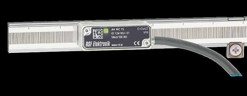
           MC 15
ABSOLUTE EXPOSED
 LINEAR ENCODERS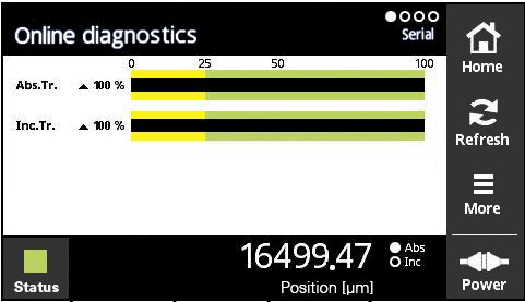
Absolute Position valuation
Large mounting tolerances
Serial interfaces
Status display directly at the
scanning head via LED function
ABSOLUTE MEASUREMENT REQUIREMENTS ON AN ABSOLUTE
PRINCIPLE LINEAR ENCODER
This means the position valuation from evaluating one unique AVOIDING REFERENCING
code information at any point over the entire measuring length. ADVANCED OPERATIONAL SAFETY
For this the scanning head needs not to be moved relative to the graduation HIGH TRAVERSING SPEED
carrier, so that the position value is available immediately after power-on.
SMALL DIMENSIONS
Reference points and reference drives are thus not required.
The subsequent electronics may access this position value at any time. NO MECHANICAL BACKLASH
ZERO FRICTIONAL FORCE
WEAR-FREE OPERATION
TERM EXPLANATIONS
Absolute position indexing Accuracy
Serial encoding of a line sequence as a highly precise graduation. This is a fundamental characteristic, which is specified with an accuracy
grade (e.g. ±5 µm/m).
Scanning head
Opto-electronic scanning device of a graduation. Measuring step
The smallest digital counting step produced by an encoder.
Yaw angle, pitch angle, roll angle, displacement, gap tolerance
Mounting tolerances of the scanning head relative to the graduation carrier.
Δ........ Delta
φ....... Phi
02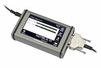
www.rsf.at
PIN ASSIGNMENTS
Coupling M12, male, 8-pin according to IEC 61076-2-101 LM008–Gxx-A D-sub connector, male, 15-pin
EnDat 2.2 Voltage supply Absolute position values
8 2 5 1 3 4 7 6
4 12 2 10 5 13 8 15
EnDat 2.2 UP Sensor 0V Sensor DATA DATA CLOCK CLOCK
UP 0V
Brown/Green Blue White/Green White Grey Pink Violet Yellow
BiSS C
8 2 5 1 3 4 7 6
4 12 2 10 5 13 8 15
BiSS/Cu UP Sensor 0V Sensor SLO+ SLO− MA+ MA−
UP 0V
Brown/Green Blue White/Green White Grey Pink Violet Yellow
Fanuc
8 2 5 1 3 4 7 6
4 12 2 10 5 13 8 15
Fanuc05 UP Sensor 0V Sensor Serial Data Serial Data Request Request
αi Interface UP 0V
Brown/Green Blue White/Green White Grey Pink Violet Yellow
Mitsubishi
8 2 5 1 3 4 7 6
4 12 2 10 5 13 8 15
Mit03-4 UP Sensor 0V Sensor Serial Data Serial Data Request Request
UP 0V Frame Frame
Mit03-2 Occupied * Occupied * Request/ Request/
Data Data
Brown/Green Blue White/Green White Grey Pink Violet Yellow
Panasonic
8 2 5 1 3 4 7 6
4 12 2 10 5 13 8 15
Pana02 UP Sensor 0V Sensor Occupied * Occupied * Request/ Request/
UP 0V Data Data
Brown/Green Blue White/Green White Grey Pink Violet Yellow
Yaskawa
8 2 5 1 3 4 7 6
4 12 2 10 5 13 8 15
YEC07 UP Sensor 0V Sensor Occupied * Occupied * DATA DATA
UP 0V
Brown/Green Blue White/Green White Grey Pink Violet Yellow
UP = Power supply voltage The shield is connected with the chassis.
Sensor: The sensor line is connected in the Not connected pins or wires must not be used.
scanning head with the corresponding power line. * Required for adjustment/inspection by PWT 101.
03SERIAL INTERFACES
EnDat 2.2 Interface EnDat 2.2 serial bidirectional
The EnDat interface is a digital, bidirectional interface for enco-
ders. It is capable both of transmitting position values as well as Data transfer Position values, parameters and additional data
transmitting or updating information stored in the encoder, or
of saving new information. Thanks to the serial transmission Differential line receiver according to EIA standard RS 485
method, only four signal lines are required. The data is transmitted Data input
for the signals CLOCK, CLOCK, DATA and DATA
in synchronism with the clock signal from the subsequent elec-
tronics. The type of transmission (position values, parameters, Differential line driver according to EIA standard
Data output
diagnostics, etc.) is selected through mode commands that the RS 485 for DATA and DATA signals
subsequent electronics send to the encoder.
Position values Ascending during traverse in direction of cable outlet
Power supply 3.6 V to 14 V
CLOCK FREQUENCY
The clock frequency is variable—depending on the cable length
(max. 150 m)—between 100 kHz and 2 MHz. With propagation-
delay compensation in the subsequent electronics, either clock
frequencies up to 16 MHz are possible or cable lengths up to 100 m.
The maximum clock frequency is stored in the encoder memory.
EnDat 2.2 ≤ 8 MHz or 16 MHz
Transmission frequencies up to 16 MHz in combination with large
cable lengths place high technological demands on the cable. Due
to the data transfer technology, the cable connected directly to the
encoder must not be longer than 20 m. Greater cable lengths can
be realized with a cable no longer than 6 m and an extension cable.
As a rule, the entire transmission path must be designed for the
respective clock frequency.
POSITION VALUES ADDITIONAL DATA
The position value can be transmitted with or without additional One or two items of additional data can be appended to the position value, depending
data. It is not transmitted to the subsequent electronics until after on the type of transmission (selection via MRS code). The additional data supported
the calculation time tcal has passed. The calculation time is ascer- by the respective encoder is saved in the encoder parameters.
tained at the highest clock frequency permissible for the encoder,
but limited at 8 MHz.
Only the required number of bits is transferred for the position value.
The bit number can be read out from the encoder for automatic
parameterization.
MEMORY AREAS
The encoder provides several memory areas for parameters. These
can be read from by the subsequent electronics, and some can be
written to by the encoder manufacturer, the OEM, or even the end
user. The parameter data are stored in a permanent memory. This
memory permits only a limited number of write access events and
is not designed for cyclic data storage. Certain memory areas can
be write-protected (this can only be reset by the encoder manu-
facturer).
Parameters are saved in various memory areas, e.g.:
Encoder-specific informationen
Informationen of the OEM (e. g. „electronic ID-label“
of the motor)
Operating parameters (datum shift, instruction, etc.)
Operating status (alarm or warning messages)
Monitoring and diagnostic functions of the EnDat interface make a
detailed inspection of the encoder possible.
Error messages
Warnings
Online diagnostics based on valuation numbers (EnDat 2.2)
04www.rsf.at
INPUT CIRCUITRY OF SUBSEQUENT ELECTRONICS
Dimensioning
IC1 = RS 485 differential line receiver
Z0 = 120 Ω
EnDat2.2 is a bidirectional interface of HEIDENHAIN.
Detailed information you will find on: www.endat.de
CUSTOMER-SPECIFIC SERIAL INTERFACES
BiSS C Panasonic
RSF Elektronik encoders with the Code B after the model RSF Elektronik encoders with the Code P after the model
designation are suited for connection to Biss C controls with designation are suited for connection to Panasonic controls with
BiSS C unidirectional interface Panasonic Serial Interface
Ordering designation: BiSS/Cu Ordering designation: Pana02
Fanuc Yaskawa
RSF Elektronik encoders with the Code F after the model RSF Elektronik encoders with the Code Y after the model
designation are suited for connection to Fanuc controls with designation are suited for connection to Yaskawa controls with
Fanuc Serial Interface Yaskawa Serial Interface
Ordering designation: Fanuc05 αi Interface Ordering designation: YEC07
Mitsubishi
RSF Elektronik encoders with the Code M after the model
designation are suited for connection to Mitsubishi controls with
Mitsubishi high speed interface
Ordering designation: Mit03-2
One-pair transmission
Ordering designation: Mit03-4
Two-pair transmission
SHIELDING
Shielded PUR-cable, Bending radius Bending radius
Drag chain qualified. fixed mounting continuous flexing
05MC 15 MK TECHNICAL DATA
SCANNING HEAD
Model AK MC 15 AK MC 15 B AK MC 15 F AK MC 15 M AK MC 15 P AK MC 15 Y
Interface EnDat 2.2 BiSS C Fanuc serial interface Mitsubishi high speed Panasonic Yaskawa
unidirectional αi Interface interface serial interface serial interface
Version EnDat 2.2 BiSS/Cu Fanuc05 Mit03-4 Mit03-2 Pana02 YEC07
Measuring step 0,1 µm (100 nm)
0,05 µm (50 nm)
Calculation time tcal ≤ 5 µs -- -- -- -- --
Clock frequency ≤ 16 MHz -- -- -- -- --
Traversing speed ≤ 600 m/min
Interpolation error Approx. ±1 µm
Electrical connection Cable, 1 m or 3 m with M12-connector 8-pin or D-sub connector 15-pin
Voltage supply DC 3.6 V to 14 V (3.6 V at least required in the scanning head)
At 3.6 V: ≤ 950 mW
Power consumption
At 14 V: ≤ 1050 mW
Current consumption typ. At 5 V: 100 mA (without load)
Vibration 55 Hz to 2000 Hz ≤ 500 m/s2 (EN 60 068-2-6)
Shock 6 ms ≤ 1000 m/s2 (EN 60 068-2-27)
Operating temperature −10 °C to 70 °C
Storage temperature −20 °C to 70 °C
Mass Scanning head: 12 g (without cable), connecting cable: 22 g/m, connector: M12-connector: 15 g; D-sub connector: 28 g
GRADUATION CARRIER
Model MB MC 15 MK: Steel tape scale with absolute track and adhesive tape
Coefficient of linear expansion α ≈ 10 × 10-6/K
Accuracy grade * ±15 µm/m
Measuring length ML Up to 10000 mm; longer lengths on request
Mass Scale tape 17 g/m
* At 20 °C
CONFORMITIES AND CERTIFICATIONS
RoHS 2011/65/EU, 2015/863/EU
EMV 2014/30/EU
Product-Certifications UL, CSA, EN, IEC 61010-1
06www.rsf.at
MC 15 MK
Steel tape scale with absolute track
and adhesive tape
Dimensions, mounting tolerances:
Tape mounting tool TMT MS 15 MK (optional)
For safe and precise mounting of the steel tape scale.
Mount TMT MS 15 MK instead of the MC 15 scanning head.
Thread steel tape scale (version MK) and move along the scale length.
Remove TMT MS 15 MK, mount MC 15 scanning head.
07MC 15 MP TECHNICAL DATA
SCANNING HEAD
Model AK MC 15 AK MC 15 B AK MC 15 F AK MC 15 M AK MC 15 P AK MC 15 Y
Interface EnDat 2.2 BiSS C Fanuc serial interface Mitsubishi high speed Panasonic Yaskawa
unidirectional αi Interface interface serial interface serial interface
Version EnDat 2.2 BiSS/Cu Fanuc05 Mit03-4 Mit03-2 Pana02 YEC07
Measuring step 0,1 µm (100 nm)
0,05 µm (50 nm)
Calculation time tcal ≤ 5 µs -- -- -- -- --
Clock frequency ≤ 16 MHz -- -- -- -- --
Traversing speed ≤ 600 m/min
Interpolation error Approx. ±1 µm
Electrical connection Cable, 1 m or 3 m with M12-connector 8-pin or D-sub connector 15-pin
Voltage supply DC 3.6 V to 14 V (3.6 V at least required in the scanning head)
At 3.6 V: ≤ 950 mW
Power consumption
At 14 V: ≤ 1050 mW
Current consumption typ. At 5 V: 100 mA (without load)
Vibration 55 Hz to 2000 Hz ≤ 500 m/s2 (EN 60 068-2-6)
Shock 6 ms ≤ 1000 m/s2 (EN 60 068-2-27)
Operating temperature −10 °C to 70 °C
Storage temperature −20 °C to 70 °C
Mass Scanning head: 12 g (without cable), connecting cable: 22 g/m, connector: M12-connector: 15 g; D-sub connector: 28 g
GRADUATION CARRIER
Model MC 15 MP: Steel tape scale with absolute track in aluminum carrier with clamping element
Coefficient of linear expansion α ≈ 10 × 10-6/K
Accuracy grade * ±15 µm/m
Measuring length ML Up to 10000 mm; longer lengths on request
Mass Scale tape 20 g/m
Aluminum carrier + 72 g/m +
Clamping element 2g
* At 20 °C
CONFORMITIES AND CERTIFICATIONS
RoHS 2011/65/EU, 2015/863/EU
EMV 2014/30/EU
Product-Certifications UL, CSA, EN, IEC 61010-1
08www.rsf.at
MC 15 MP
Steel tape scale with absolute track
in aluminum carrier with clamping element
Clamping element bolted
Carrier with adhesive tape
Dimensions, mounting tolerances:
09ACCESSORY: EXTERNAL TESTING DEVICE PWT 101
The PWT 101 is a testing device for checking the function and adjustment
of absolute RSF Elektronik encoders. Thanks to its compact dimensions and
robust design, the PWT 101 is ideal for mobile use. A 4.3-inch touchscreen
provides for display and operation.
For example, for encoders with EnDat interface you can not only display
the position value but also export the online diagnosis, shift datums, and
perform further inspection functions.
AVAILABLE FUNCTIONS
The performance range of the PWT 101 can be expanded by firmware
update. Appropriate firmware files that can be imported to the PWT 101
through a memory card (not included in delivery) will be made available at
www.heidenhain.de.
Mitsubishi 03-4, 03-2
Panasonic02
Feature content of the PWT 101
EnDat 2.2
Fanuc05
BiSS/Cu
YEC 07
Position display
Display of the absolute position
Display and resetting of error messages
Display and resetting of warnings
Display of transmission status
Diagnostics
Display of online diagnostics
Display of supply voltage and supply current
Additional functions (if supported by the encoder) -- -- -- -- --
Datum shift („electrical zeroing of position“)
Memory contents
Display of encoder information
STATUS DISPLAY VIA LED FUNCTION
Mitsubishi 03-4, 03-2
LED function
Panasonic02
Note
at the scanning head
EnDat 2.2
Fanuc05
BiSS/Cu
YEC 07
GREEN
Very good
YELLOW Check mounting,
-- -- --
Warning clean encoder
RED Check mounting,
Alarm clean encoder
10www.rsf.at
FURTHER PRODUCTS
MCR 15 | MCS 15 MSR 15 | MSS 15 MSR 45
Absolute modular angle encoders Incremental modular angle encoders Modular angle encoders
with small dimensions with small dimensions with steel tape scale -
Diverse serial interfaces Quality of the scanning signals is various versions
Status display directly at the directly visible at the scanning Full-circle or segment version
scanning head via LED function head via a tricolored LED function Grating period: 200 µm
Easy mounting as a result of Easy mounting as a result of Accuracy of the grating
large mounting tolerances large mounting tolerances (stretched): ±30 µm/m
High insensitivity against High insensitivity against High permissible
contaminations contaminations rotational speed resp.
Possible drum diameter (TTR): Possible drum diameter (TTR): circumferential speed
50.00 mm to 350.23 mm (outside) 50.00 mm to 350.23 mm (outside) Integrated subdividing:
Possible scanning diameter (MBR): Possible scanning diameter (MBR): up to times 100
59.93 mm to 350.23 mm (outside) 59.93 mm to 350.23 mm (outside) Possible diameter:
Possible scanning diameter (MCS): Possible scanning diameter (MSS): Full-circle from Ø 146.99 mm
from 75 mm from 75 mm Segment from Ø 150 mm
MS 15 MS 25 MS 45
Exposed linear encoders Exposed scanning linear encoders Exposed linear encoders
with integrated mounting control with integrated mounting control with integrated mounting control
Easy mounting; no test box Easy mounting; no test box Easy mounting; no test box
or oscilloscope needed or oscilloscope needed or oscilloscope needed
Quality of the scanning signals is Quality of the scanning signals is Quality of the scanning signals is
directly visible at the scanning directly visible at the scanning head directly visible at the scanning
head via a tricolored LED function via a tricolored LED function head via a tricolored LED function
Two independent switch tracks Two independent switch tracks Flat dimensions
for individual special functions for individual special functions Easy mounting due to large
Position of reference mark Position of reference mark mounting tolerances
selectable by customer selectable by customer High insensitivity against
High insensitivity against High insensitivity against contamination
contamination contamination High permissible traversing speed
High permissible traversing speed High permissible traversing speed Integrated subdividing:
Integrated subdividing: Integrated subdividing: up to times 100
up to times 200 up to times 200 Max. measuring length:
Max. measuring length: Max. measuring length Steel tape scale: 30 000 mm
Steel tape scale: 20 000 mm Glass scale: 3140 mm
Glass scale: 3140 mm Steel tape scale: 20 000 mm
11DISTRIBUTION CONTACTS
AUSTRIA RSF Elektronik Ges.m.b.H. A-5121 Tarsdorf 93 +43 62 78 81 92-0 e-mail: info@rsf.at
+43 62 78 81 92-79 internet: www.rsf.at
Corporate Head Quarters
BELGIUM HEIDENHAIN NV/SA Pamelse Klei 47 +32 (54) 34 3158 e-mail: sales@heidenhain.be
1760 Roosdaal +32 (54) 34 3173 internet: www.heidenhain.be
FRANCE HEIDENHAIN FRANCE sarl 2 Avenue de la Christallerie +33 1 41 14 30 00 e-mail: info@heidenhain.fr
92310 Sèvres +33 1 41 14 30 30 internet: www.heidenhain.fr
GREAT BRITAIN HEIDENHAIN (GB) Ltd. 200 London Road +44 1444 247711 e-mail: sales@heidenhain.co.uk
Burgess Hill +44 1444 870024 internet: www.heidenhain.co.uk
West Sussex RH15 9RD
ITALY HEIDENHAIN ITALIANA S.r.l. Via Asiago, 14 +39 02 27075-1 e-mail: info@heidenhain.it
20128 Milan +39 02 27075-210 internet: www.heidenhain.it
NETHERLANDS HEIDENHAIN NEDERLAND B.V. Copernicuslaan 34 +31 318-581800 e-mail: verkoop@heidenhain.nl
6716 BM EDE +31 318-581870 internet: www.heidenhain.nl
SPAIN FARRESA ELECTRONICA S.A Les Corts 36-38 +34 93 4 092 491 e-mail: farresa@farresa.es
08028 Barcelona + 34 93 3 395 117 internet: www.farresa.es
SWEDEN HEIDENHAIN Scandinavia AB Storsätragränd 5 +46 8 531 933 50 e-mail: sales@heidenhain.se
SE-12739 Skärholmen +46 8 531 933 77 internet: www.heidenhain.se
SWITZERLAND HEIDENHAIN (SCHWEIZ) AG Vieristrasse 14 +41 44 806 27 27 e-mail: verkauf@heidenhain.ch
8603 Schwerzenbach +41 44 806 27 28 internet: www.heidenhain.ch
CHINA DR. JOHANNES HEIDENHAIN Tian Wei San Jie, Area A, +86 10 80 42-0000 e-mail: sales@heidenhain.com.cn
Beijing Tianzhu Airport Industrial Zone internet: www.heidenhain.com.cn
(CHINA) Co., Ltd
Shunyi District, Beijing 101312
ISRAEL MEDITAL Hi-Tech 36 Shacham St., P.O.Box 7772 +972 0 3 923 33 23 e-mail: avi@medital.co.il
4951729 Petach Tikva +972 0 3 923 16 66 internet: www.medital.co.il
JAPAN HEIDENHAIN K.K. Hulic Kojimachi Bldg., +81 3 3234 7781 e-mail: sales@heidenhain.co.jp
9F 3-2 Kojimachi, Chiyoda-ku +81 3 3262 2539 internet: www.heidenhain.co.jp
Tokyo, 102-0083
KOREA HEIDENHAIN LTD. 75, Jeonpa-ro 24beon-gil, +82 31 380 5200 e-mail: info@heidenhain.co.kr
Manan-gu, Anyang-si +82 31 380 5250 internet: www.rsf.co.kr
14087 Gyeonggi-do
SINGAPORE HEIDENHAIN PACIFIC PTE LTD. 51, Ubi Crescent +65 67 49 32 38 e-mail: info@heidenhain.com.sg
408593 Singapore +65 67 49 39 22 internet: www.heidenhain.com.sg
TAIWAN HEIDENHAIN CO., LTD. No. 29, 33rd Road; +886 4 2358 89 77 e-mail: info@heidenhain.tw
Taichung Industrial Park +886 4 2358 89 78 internet: www.heidenhain.com.tw
Taichung 40768
USA HEIDENHAIN CORPORATION 333 East State Parkway +1 847 490 11 91 e-mail: info@heidenhain.com
Schaumburg, IL 60173-5337 internet: www.rsf.net
Date 05/2021 Art.No. 1210495-03 Doc.No. D1210495-04-A-01 Technical adjustments in reserve!
Linear and Angle Encoders Certified acc. to
Precision Graduations ISO 9001
ISO 14001
Ges.m.b.H.
A-5121 Tarsdorf +43 (0)6278 / 8192-0 +43 (0)6278 / 8192-79 e-mail: info@rsf.at internet: www.rsf.atYou can also read


