Document number CMM_685_Ulyser
←
→
Page content transcription
If your browser does not render page correctly, please read the page content below
1see

 Document number CMM_685_Ulyser
 No. MA_Ulyser_CMM_E_Rev_2.0

                                                         Ulyser Component Maintenance Manual

Novega Produktionssysteme GmbH
Gewerbepark 2 | 87477 Sulzberg (See) | Germany
Fon: +49/8376/92990-0 | Fax: +49/8376/92990-20
info@novega.de | www.novega-sky.com

PNR:                22097-00
PNR Revision:       00                                Issue No.: 2
Cage Code:          CG871                        Amendment No.: 4
ECCN:               7B994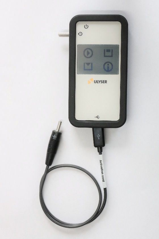
Document Title:

                                  Ulyser Component Maintenance Manual
                              Document Name:
                                                     CMM_685_Ulyser

Item Type:                       Tester and Analyser for Underwater Locating Devices
Item Name:                       ULYSER
PNR:                             22097-00

Available Options:               Ulyser Aviation             PNR: 20538-00
                                 Ulyser Maritime             PNR: 22098-(00)-(00)

Company:                         Novega Produktionssysteme GmbH
                                 Gewerbepark 2 | 87477 Sulzberg (See) | Germany
                                 Fon: +49/8376/92990-0 | Fax: +49/8376/92990-20
                                 info@novega.de | www.novega.de

  Activity            Name                          Function        Department                  Signature

 Prepared:      Claudia Fellmann                 Technical Editor         TD

 Released:       Gerhard Günther                Technical Manager         TD

This document/data is the property of Novega. You may not possess, use, copy, or disclose this document/data or any
information contained therein, for any purpose, including without limitation to design, manufacture, or repair parts, or
obtain EASA or any other government approval to do so, without Novega express written permission. Neither receipt nor
possession, use, copying, or disclosing by anyone without Novega express written permission is not authorized and may
result in criminal and/or civil liability. This document/data remains the property of Novega. This document/data is not
releasable under the “freedom of information act”.
                         © Copyright by Novega Produktionssysteme GmbH all rights reserved.
                                            Table 1-1: Authorizations Table

Issue No. 2          Amendment No. 4                        15 Mar 2021                               Page 2 of 25
                           © Novega 2021, confidential and proprietary document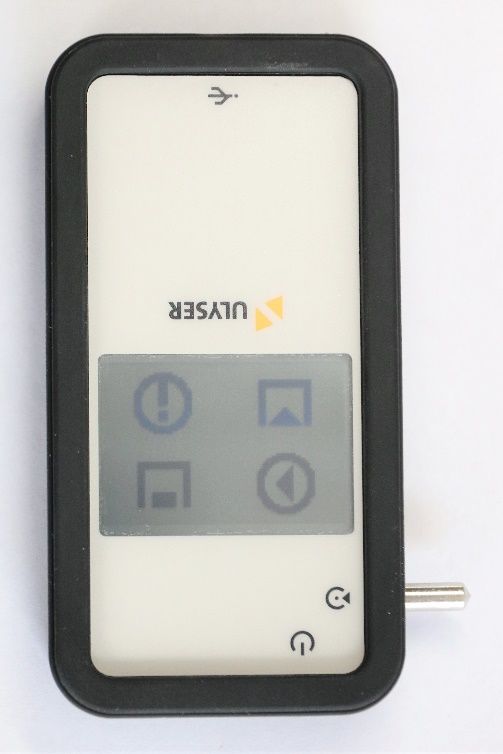
Document Title:

                                            Ulyser Component Maintenance Manual
                                       Document Name:
                                                                 CMM_685_Ulyser

1.0 Administration
1.1 Table of Contents
1.0 Administration ...................................................................................................................... 3
    1.1 Table of Contents .................................................................................................................. 3
2.0 Introduction.......................................................................................................................... 5
    2.1 Log of Revisions..................................................................................................................... 5
    2.2 Definitions ............................................................................................................................. 5
    2.3 Abbreviations ........................................................................................................................ 6
3.0 General................................................................................................................................. 6
    3.1 Description ............................................................................................................................ 6
    3.2 Type Plate Example ............................................................................................................... 7
    3.3 Works Test Sticker ................................................................................................................ 7
    3.4 Specification .......................................................................................................................... 7
    3.5 List of Components ............................................................................................................... 8
4.0 Device Description of the Ulyser ...........................................................................................10
    4.1 Device Description .............................................................................................................. 10
    4.2 Setup the Ulyser.................................................................................................................. 11
    4.3 Menu Description ............................................................................................................... 12
                4.3.1       Start Screen ........................................................................................................................ 12
                4.3.2       Start Menu ......................................................................................................................... 12
                4.3.3       Connecting Screen ............................................................................................................. 12
                4.3.4       Measurement Screen ......................................................................................................... 13
                4.3.5       Memory Screen .................................................................................................................. 13
                4.3.6       Sending Screen ................................................................................................................... 13
                4.3.7       Info Screen ......................................................................................................................... 14
                4.3.8       Low Battery Screen ............................................................................................................ 14
5.0 Fault Isolation ......................................................................................................................14
6.0 Test Procedure.....................................................................................................................16
    6.1 General................................................................................................................................ 16
    6.2 Functional Test and Readout ULD....................................................................................... 16
    6.3 Functional Test and Readout LF-ULD .................................................................................. 17
7.0 ULD Report Creator ..............................................................................................................19
    7.1 Setup ULD Report Creator .................................................................................................. 19
    7.2 Data Transfer ...................................................................................................................... 20
    7.3 Analyse the transferred Data .............................................................................................. 21
                7.3.1       Test passed ......................................................................................................................... 21
                7.3.2       Test failed ........................................................................................................................... 22
    7.4 Report Creation................................................................................................................... 23
8.0 Maintenance .......................................................................................................................24
    8.1 Battery Replacement .......................................................................................................... 24
    8.2 Annual Works Test .............................................................................................................. 25
    8.3 End of Service Life ............................................................................................................... 25
    8.4 Returns ................................................................................................................................ 25
    8.5 Service Address ................................................................................................................... 25
9.0 Warranty and Guaranty .......................................................................................................25

 Issue No. 2               Amendment No. 4                                  15 Mar 2021                                                     Page 3 of 25
                                  © Novega 2021, confidential and proprietary document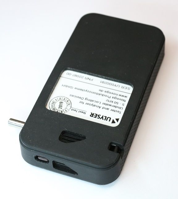
Document Title:

                                            Ulyser Component Maintenance Manual
                                        Document Name:
                                                               CMM_685_Ulyser

List of Figures

Figure 1: Ulyser ........................................................................................................................................ 6
Figure 2: Type Plate Example .................................................................................................................. 7
Figure 3: Works Test Sticker .................................................................................................................... 7
Figure 4: Ulyser ........................................................................................................................................ 8
Figure 5: Short USB Cord ......................................................................................................................... 8
Figure 6: Activation Cord ......................................................................................................................... 8
Figure 7: Activation Cord for SID88 ......................................................................................................... 9
Figure 8: Case for the Ulyser ................................................................................................................... 9
Figure 9: Ulyser Front Side .................................................................................................................... 10
Figure 10: Ulyser Back Side ................................................................................................................... 10
Figure 11: Setup Ulyser for ULD ............................................................................................................ 11
Figure 12: Setup Ulyser for LF-ULD........................................................................................................ 11
Figure 13: Start Screen .......................................................................................................................... 12
Figure 14: Start Menu............................................................................................................................ 12
Figure 15: Connecting Screen ................................................................................................................ 12
Figure 16: Connecting Screen with Process Bar .................................................................................... 12
Figure 17: Measurement ....................................................................................................................... 13
Figure 18: Measurement Signal OK Symbol .......................................................................................... 13
Figure 19: Memory Screen .................................................................................................................... 13
Figure 20: Sending Screen ..................................................................................................................... 13
Figure 21: Info Screen............................................................................................................................ 14
Figure 22: Low Battery Screen............................................................................................................... 14
Figure 23: Functional Test with an example ULD .................................................................................. 16
Figure 24: Connected with Minus Pole (Battery Cap with 3 Boreholes) ............................................... 17
Figure 25: Connected with Plus Pole ..................................................................................................... 17
Figure 26: Checking the Acoustic Signal ................................................................................................ 17
Figure 27: Functional Test with an example LF-ULD ............................................................................. 17
Figure 28: Connecting............................................................................................................................ 18
Figure 29: Checking the Acoustic Signal ................................................................................................ 18
Figure 30: ULD Report Creator: Your Company Data ............................................................................ 19
Figure 31: ULD Report Creator: Connecting .......................................................................................... 20
Figure 32: ULD Report Creator Program: Test passed .......................................................................... 21
Figure 33: ULD Report Creator Program: Test failed............................................................................. 22
Figure 34: Test Report ........................................................................................................................... 23
Figure 35: Battery Cover........................................................................................................................ 24
Figure 36: Battery Replacement ............................................................................................................ 24

List of Tables

Table 1-1: Authorizations Table .............................................................................................................. 2
Table 2-1: Log of Revisions ...................................................................................................................... 5
Table 3-1: Specification ........................................................................................................................... 7

 Issue No. 2                Amendment No. 4                               15 Mar 2021                                              Page 4 of 25
                                    © Novega 2021, confidential and proprietary document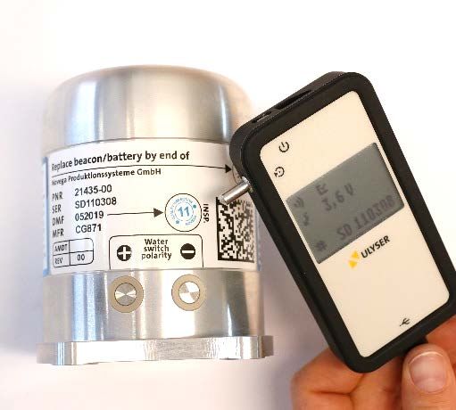
Document Title:

                               Ulyser Component Maintenance Manual
                           Document Name:
                                                  CMM_685_Ulyser

2.0 Introduction
This manual contains the description, as well as instructions for use and maintenance directions for
the Ulyser.

Note: This manual must be read completely before using the Ulyser.

2.1 Log of Revisions
The following table summarizes the issue and amendment level evolution, tracing the changes in the
affected paragraphs.

 Issue   Amendment Date                      Description                                 Affected paragraphs

   1           0         10.02.2017          First release of document                             -
   1           1         04.07.2017          Change figures and content                        2.1 - 4.5
   1           2         26.09.2017          Amendment content                                    1.0
   2           0         25.06.2019          Layout und content revised                        1.0 - 9.0
   2           1         24.10.2019          CAGE Code and ECCN inserted,                     Title Page
                                             ULD Report Creator Software update to 3.1            7.0
   2           2         08.09.2020          Case for the Ulyser has changed, photos               -
                                             have been exchanged
   2           3         21.01.2021          Amendment Description “signal ok” icon             4.3.4
                                                                                                 6.2
                                                                                                 6.3
   2           4         15.03.2021          Amendment Description “Now the                      6.2
                                             jacks/plug can be removed”                          6.3
                                             Table 2-1: Log of Revisions

2.2 Definitions
“Activated” means the ULD / LF-ULD is transmitting pulses.
“ULD / LF-ULD Revalidation” means battery replacement of the ULD / LF-ULD.
“Signal” means an acoustic sound emitted by the ULD / LF-ULD.
“Pulse” in this document has the same meaning as signal.
“Pulse repetition rate” is the number of pulses emitted by the ULD / LF-ULD in a specific time,
measured in pulses per second (pulses/s).
“Qualified technician” means qualified aircraft mechanic.
“Service Operation Mode” means that the ULD / LF-ULD is activated and is transmitting pulses.
“Sleep Mode” means that the ULD / LF-ULD is not activated and is not transmitting pulses.
“ULD” and “ULB” has the same meaning. These are acoustic beacons fitted to aviation flight
recorders such as the Cockpit Voice Recorder or the Flight Data Recorder or to maritime Voyage Data
Recorders.
“LF-ULD” is an acoustic beacon fitted to the aircraft fuselage.

 Issue No. 2       Amendment No. 4                       15 Mar 2021                           Page 5 of 25
                        © Novega 2021, confidential and proprietary document
Document Title:

                                           Ulyser Component Maintenance Manual
                                       Document Name:
                                                              CMM_685_Ulyser

2.3 Abbreviations
ECCN…………………………………………………………………..………………………Export Control Classification Number
LF-ULD ..................................................................Airframe Low Frequency Underwater Locating Device
PNR ....................................................................................................................................... Part number
SER ...................................................................................................................................... Serial number
ULB .............................................................................................................. Underwater Locator Beacon
ULD .............................................................................................................. Underwater Locating Device

3.0 General
3.1 Description
The Ulyser is a battery-powered receiver for acoustic signals with a frequency of 5 to 50 kHz. The
Ulyser receives the acoustic signals via an integrated microphone. The received signals are optically
displayed via a blinking symbol and acoustically via an integrated loudspeaker. With a Ulyser a
functional test of a ULD / LF-ULD can be performed. The Ulyser measures the battery voltage and
reads out data of the ULD / LF-ULD. This data can be analysed with a special software.

          The Ulyser meets the requirements of the EU-Directives for CE marking.

                                                           Figure 1: Ulyser

 Issue No. 2               Amendment No. 4                              15 Mar 2021                                              Page 6 of 25
                                   © Novega 2021, confidential and proprietary document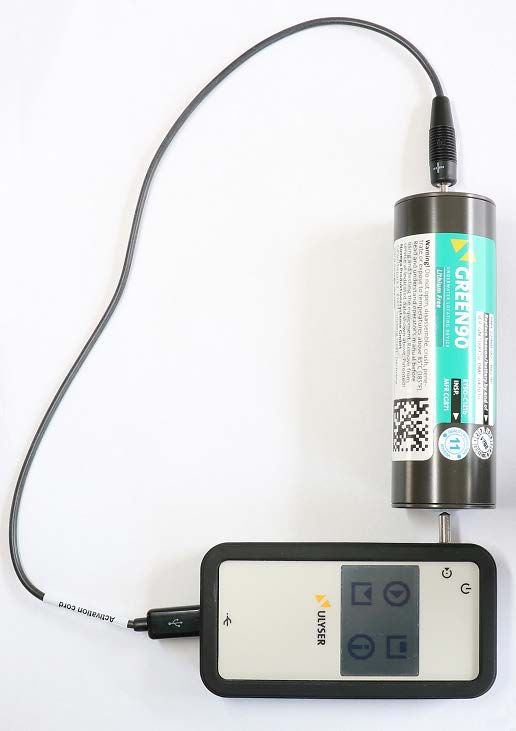
Document Title:

                                Ulyser Component Maintenance Manual
                            Document Name:
                                                CMM_685_Ulyser

3.2 Type Plate Example

                                                                                                    1

                      3                                                                       2

                                              Figure 2: Type Plate Example

                                              Legend:

   1         Works Test Sticker (see chapter 3.3)
   2         Part number (PNR)
   3         Serial number (SER)

3.3 Works Test Sticker
The works test sticker indicates the date of the next
recommended works test. The marked works test sticker is
positioned in such a way that the line points to the month when
the next works test should be performed. The year of the next
recommended test is found in the middle of the sticker.

3.4 Specification                                                                         Figure 3: Works Test Sticker

Measurement range:
Voltage:                                                                                                 2.8 to 3.6 V
Frequency:                                                                                          5 kHz to 50 kHz

Technical data:
Power supply:                                                                Button cell Lithium Type CR2032 / 3 V
Operating temperature
                                                                                   -20 °C (-4 °F) to + 60 °C (140 °F)
range:
Protection class:                                                                                                 IP44
Size (L x W x H):                                94 mm (3.70 inch) x 49 mm (1.93 inch) x 16 mm (0.63 inch)
Weight:                                                                                                 55 g (1.9 oz)
                                              Table 3-1: Specification

 Issue No. 2        Amendment No. 4                     15 Mar 2021                                  Page 7 of 25
                          © Novega 2021, confidential and proprietary document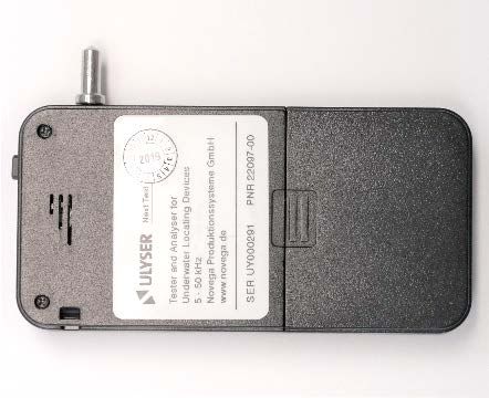
Document Title:
Ulyser Component Maintenance Manual
Document Name:
CMM_685_Ulyser
3.5 List of Components
Ulyser Ulyser
Component Figure
Maritime Aviation
1. Ulyser
Figure 4: Ulyser
2. Short USB Cord
Figure 5: Short USB Cord
3. Activation Cord
Figure 6: Activation Cord
Issue No. 2 Amendment No. 4 15 Mar 2021 Page 8 of 25
© Novega 2021, confidential and proprietary document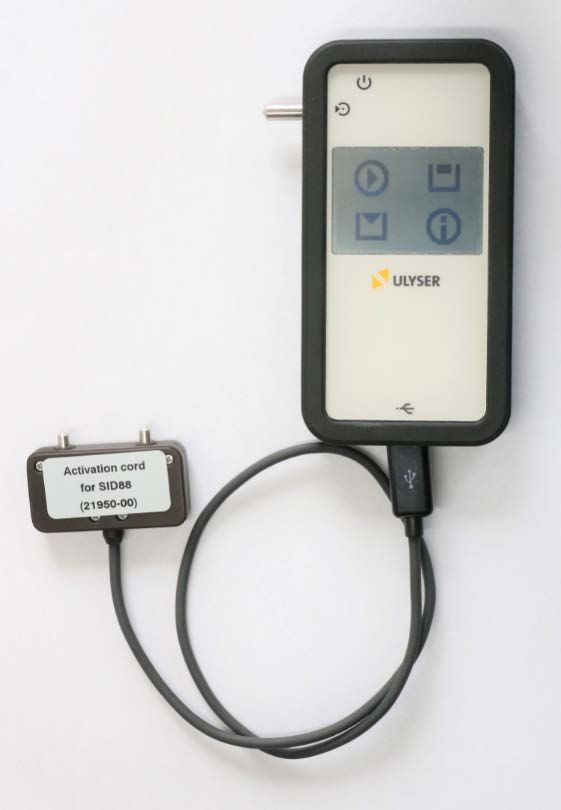
Document Title:
Ulyser Component Maintenance Manual
Document Name:
CMM_685_Ulyser
Ulyser Ulyser
Component Figure
Maritime Aviation
4. Activation Cord for
SID88
Figure 7: Activation Cord for SID88
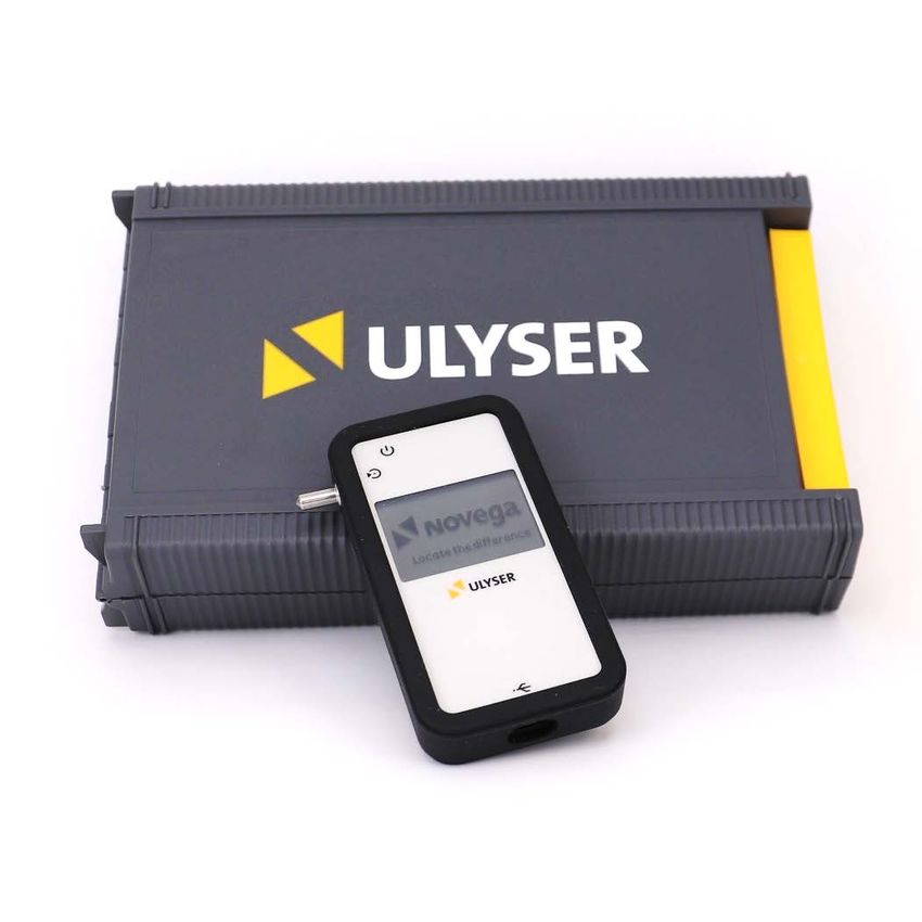
5. Case for the Ulyser and
all Components
Figure 8: Case for the Ulyser
Issue No. 2 Amendment No. 4 15 Mar 2021 Page 9 of 25
© Novega 2021, confidential and proprietary document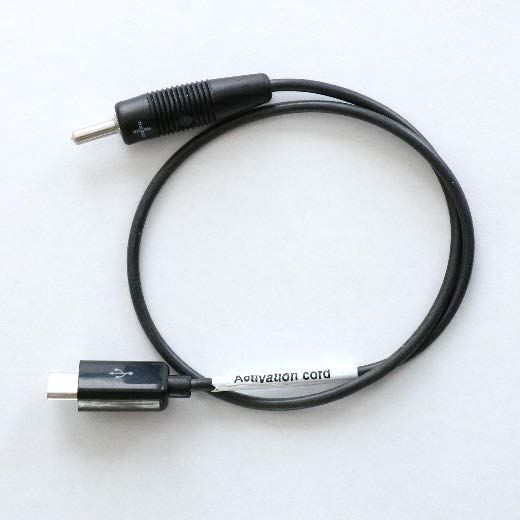
Document Title:

                                Ulyser Component Maintenance Manual
                            Document Name:
                                              CMM_685_Ulyser

4.0 Device Description of the Ulyser
4.1 Device Description

           Front Side of the Ulyser                              Back Side of the Ulyser

                                                                                                   7
   2                             1

                                                                     Figure 10: Ulyser Back Side

            Figure 9: Ulyser Front Side              4
       3
                                                           5                                           6

Legend:

   1       Touchscreen
   2       Jack / Measuring Adapter
   3       USB Micro B Port
   4       On / Off Button
   5       Loudspeaker
   6       Microphone
   7       Works Test Sticker

 Issue No. 2      Amendment No. 4                  15 Mar 2021                            Page 10 of 25
                         © Novega 2021, confidential and proprietary document
Document Title:
Ulyser Component Maintenance Manual
Document Name:
CMM_685_Ulyser
4.2 Setup the Ulyser
Setup for LF-ULD: Ulyser with Activation cord
Setup for ULD: Ulyser with Activation cord
for LF-ULD
Figure 11: Setup Ulyser for ULD Figure 12: Setup Ulyser for LF-ULD
Issue No. 2 Amendment No. 4 15 Mar 2021 Page 11 of 25
© Novega 2021, confidential and proprietary documentDocument Title:
Ulyser Component Maintenance Manual
Document Name:
CMM_685_Ulyser
4.3 Menu Description
This chapter describes the menu items. The measurement sequences are explained in chapter 6.
4.3.1 Start Screen
Turn the Ulyser on by pressing the on / off button until the
start screen appears.
Note: The Ulyser turns off automatically 2 minutes after the
last operation.
Figure 13: Start Screen
4.3.2 Start Menu
Four different functions can be selected in the start menu:
- Measurement
- Memory
- Sending
Figure 14: Start Menu
- Info Screen
4.3.3 Connecting Screen
By pressing the measurement button in the start menu
the function test starts and the connecting screen is shown.
A ULD / LF-ULD can be connected now.
Note: Return to the start menu by tapping the screen. Figure 15: Connecting Screen
If the Ulyser is successfully connected to a ULD / LF-ULD, the
measurement process for the functional test starts
automatically. The process bar is displayed and the ULD / LF-
ULD is activated. Successfully measuring is confirmed by a
single beep, the Ulyser automatically switches to the
measurement screen.
Figure 16: Connecting Screen with
Process Bar
Issue No. 2 Amendment No. 4 15 Mar 2021 Page 12 of 25
© Novega 2021, confidential and proprietary documentDocument Title:
Ulyser Component Maintenance Manual
Document Name:
CMM_685_Ulyser
4.3.4 Measurement Screen
If the measurement is successful, the
measurement data will be read out from the ULD
/ LF-ULD, displayed and automatically stored on
the Ulyser.
• The pulse symbol represents the
visualization of every received pulse.
• The pulse symbol stays active (also
visible in the start menu), as long as the Figure 17: Measurement
Ulyser receives a signal.
Note: Furthermore, the received signal is Signal OK
reproduced simultaneously in an audible way for
human ears. Battery
voltage
• The signal ok symbol Serial number
appears after the Ulyser has received Figure 18: Measurement Signal OK
Symbol
three pulses. Please note the pulse
repetition rate of the ULD / LF-ULD.
Note: Return to the start menu by tapping the
screen.
4.3.5 Memory Screen
Signal OK
By pressing the memory button , the last Battery
stored measurement data is displayed. voltage
Note: Return to the start menu by tapping the Serial number
screen. Figure 19: Memory Screen
4.3.6 Sending Screen
By pressing the sending button , the Ulyser
sends the last measured data.
Note: The Ulyser returns to the start menu
automatically. Figure 20: Sending Screen
Issue No. 2 Amendment No. 4 15 Mar 2021 Page 13 of 25
© Novega 2021, confidential and proprietary documentDocument Title:
Ulyser Component Maintenance Manual
Document Name:
CMM_685_Ulyser
4.3.7 Info Screen
By pressing the info button , the info screen
is displayed.
Note: Return to the start menu by tapping the
screen. Figure 21: Info Screen
4.3.8 Low Battery Screen
This screen is displayed, as soon as the Ulyser
has a low battery level. The battery needs to be
replaced (see chapter 8.1).
Note: The low battery screen is only displayed
after the start screen (see chapter 4.3.1) when
Figure 22: Low Battery Screen
the Ulyser is turned on. Then the Ulyser
automatically switches to the start menu.
5.0 Fault Isolation
Faults that can occur are shown in the table below with their probable causes and the correction
action.
Fault Probable cause Correction action
The battery level of the Ulyser Replace the battery, follow the
The Ulyser cannot be turned is too low. instructions in chapter 8.1.
on. The battery was not inserted Check the battery, follow the
correctly. instructions in chapter 8.1.
The wrong battery type has Check the battery, follow the
been inserted. instructions in chapter 8.1.
The Ulyser is defect. Contact our service
department (Service Address).
Issue No. 2 Amendment No. 4 15 Mar 2021 Page 14 of 25
© Novega 2021, confidential and proprietary documentDocument Title:
Ulyser Component Maintenance Manual
Document Name:
CMM_685_Ulyser
Fault Probable cause Correction action
Contact has lost during Start the functional test again.
Testing with the Ulyser does measurement or readout has
not deliver the expected result. failed.
Note: The error message Note: The next measurement
“Reading incomplete retry in can be performed when the
66 sec” appears at the Ulyser ULD / LF-ULD drops back into
after starting measurement. the sleep mode after 60
seconds.
The poles have been inverted. Note the correct orientation of
the ULD / LF-ULD and start the
functional test again.
Note: The error message Note: The next measurement
“Check polarity retry in 66 can be performed when the
sec” appears at the Ulyser ULD / LF-ULD drops back into
after starting measurement. the sleep mode after 60
seconds.
For fault isolation and the Start the functional test again.
complete testing procedure Note: The next measurement
with the Ulyser please follow can be performed when the
the instructions of chapter 6 ULD / LF-ULD drops back into
step by step. the sleep mode after 60
seconds.
The battery level of the Ulyser Replace the battery, follow the
is too low. instructions in chapter 8.1.
Note: The low battery screen is
only displayed after the start
screen (see chapter 4.3.8).
Defect of the ULD / LF-ULD Check the ULD / LF-ULD.
Defect of the Ulyser Contact our service
department (Service Address).
Defect of the activation cord Contact our service
department (Service Address).
Bad contact on the water Clean the water switch pins of
Impossibility of switching the
switch pins of the the ULD / LF-ULD with a soft
ULD / LF-ULD in the “service
ULD / LF-ULD cloth and a mild detergent.
operation mode”.
Defect of the ULD / LF-ULD Check the ULD / LF-ULD.
The Ulyser has not received Hold the Ulyser in the direction
three pulses. of the ULD / LF-ULD to prevent
The signal ok Symbol Note the pulse repetition rate losing the acoustic signal.
does not appear. of the ULD / LF-ULD.
The Ulyser is no longer in the Start the functional test again.
service operation mode. Note: The next measurement
can be performed when the
ULD / LF-ULD drops back into
the sleep mode after 60
seconds.
Issue No. 2 Amendment No. 4 15 Mar 2021 Page 15 of 25
© Novega 2021, confidential and proprietary documentDocument Title:
Ulyser Component Maintenance Manual
Document Name:
CMM_685_Ulyser
6.0 Test Procedure
6.1 General
Clean the water switch pins of the ULD / LF-ULD with a soft cloth and a mild detergent before each
test of the ULD / LF-ULD, and dry them carefully with a clean cloth. The Ulyser is a sensitive
instrument. Therefore, it is to be protected from moisture and destruction.
Note: Surrounding sounds can affect the measurement by triggering an acoustic signal.
Note: The Ulyser turns off automatically 2 minutes after the last operation, data of the last readout
remains recorded under normal conditions (e.g. battery level not low) on the Ulyser.
6.2 Functional Test and Readout ULD
Perform the following steps for the functional test with the ULD:
Step 1: Plug the activation cord to the
USB port.
Step 2: Turn the Ulyser on by pressing
the on / off button until the start
screen appears.
Step 3: Press the measurement button
to start the functional test.
Step 4: Connect both jacks with the
correct poles of the ULD. Note
the correct orientation of the
ULD (see figure 23, 24, 25). Figure 23: Functional Test with an example ULD
Note: The error message “Check polarity retry in 66 sec” appears when the poles
have been inverted. In this case the ULD is also activated. The value time of 66
seconds is necessary because the ULD is in the service operation mode. The next
measurement can be performed when the ULD drops back into the sleep mode.
Step 5: The measurement process for the functional test starts automatically. The process
bar is displayed and the ULD is activated. Successfully measuring is confirmed by a
single beep, the Ulyser automatically switches to the measurement screen. Now the
jacks can be removed.
Note: The error message “Reading incomplete retry in 66 sec” appears when
contact is lost during measurement or the readout has failed. The ULD is activated.
The value time of 66 seconds is necessary because the ULD is in the service
operation mode. The next measurement can be performed when the ULD drops
back into the sleep mode.
Issue No. 2 Amendment No. 4 15 Mar 2021 Page 16 of 25
© Novega 2021, confidential and proprietary documentDocument Title:
Ulyser Component Maintenance Manual
Document Name:
CMM_685_Ulyser
Step 6: The acoustic signal which the activated ULD emits can be checked with the Ulyser.
Note: The Ulyser has to be held in the direction of the ULD to prevent losing the
acoustic signal (see figure 26).
Step 7: The functional test is successful when the “signal ok” icon (see figure 18) appears,
the Ulyser has received three valid pulses.
Note: To be sure, that the ULD switches back to the “sleep mode”, wait until the
pulse symbol on the display disappears and the audible pulse repetition of the
Ulyser stops.
Figure 26: Checking the Acoustic
Figure 24: Connected with Minus
Figure 25: Connected with Plus Pole Signal
Pole (Battery Cap with 3 Boreholes)
6.3 Functional Test and Readout LF-ULD
Perform the following steps for the functional test with
the LF-ULD:
Step 1: Plug the activation cord for LF-ULD in the
USB port.
Step 2: Turn the Ulyser on by pressing the on / off
button until the start screen appears.
Step 3: Press the measurement button to start
the functional test.
Step 4: Connect the plug with the correct poles of
the LF-ULD. Note the correct orientation of
the plug (see figure 27, 28).
Figure 27: Functional Test with an example LF-ULD
Issue No. 2 Amendment No. 4 15 Mar 2021 Page 17 of 25
© Novega 2021, confidential and proprietary documentDocument Title:
Ulyser Component Maintenance Manual
Document Name:
CMM_685_Ulyser
Note: The error message “Check polarity retry in 66 sec” appears when the poles
have been inverted. In this case the LF-ULD is also activated. The value time of 66
seconds is necessary because the LF-ULD is in the service operation mode. The next
measurement can be performed when the LF-ULD drops back into the sleep mode.
Step 5: The measurement process for the functional test starts automatically. The process
bar is displayed and the LF-ULD is activated. Successfully measuring is confirmed by
a single beep, the Ulyser automatically switches to the measurement screen. Now
the plug can be removed.
Note: The error message “Reading incomplete retry in 66 sec” appears when
contact is lost during measurement or the readout has failed. The LF-ULD is
activated. The value time of 66 seconds is necessary because the LF-ULD is in the
service operation mode. The next measurement can be performed when the LF-ULD
drops back into the sleep mode.
Step 6: The acoustic signal which the activated LF-ULD emits can be checked with the
Ulyser.
Note: The Ulyser has to be held in the direction of the LF-ULD to prevent losing the
acoustic signal (see figure 29).
Step 7: The functional test is successful when the “signal ok” icon (see figure 18) appears,
the Ulyser has received three valid pulses.
Note: To be sure, that the LF-ULD switches back to the “sleep mode”, wait until the
pulse symbol on the display disappears and the audible pulse repetition of the
Ulyser stops.
Figure 28: Connecting Figure 29: Checking the Acoustic
Signal
Issue No. 2 Amendment No. 4 15 Mar 2021 Page 18 of 25
© Novega 2021, confidential and proprietary documentDocument Title:
Ulyser Component Maintenance Manual
Document Name:
CMM_685_Ulyser
7.0 ULD Report Creator
7.1 Setup ULD Report Creator
To transfer the readout data from the Ulyser to the PC, the ULD Report Creator needs to be installed
on the PC. The software is provided as zip-file by e-mail. Uninstall an old software version before
installing a new software version.
Note: The ULD Report Creator Software requires a computer with Window 7 or higher and
“Microsoft.NET Framework 4.6.1” or higher as minimum system requirements.
Perform the following steps to setup the ULD Report Creator:
Step 1: Start the ULD Report Creator.
Step 2: Fill in the fields marked in red with your company data (see figure 30).
Figure 30: ULD Report Creator: Your Company Data
Step 3: It is possible to upload an own company logo for the test
report (see figure 30):
Note: At the next software start, the entered data will be displayed again.
Issue No. 2 Amendment No. 4 15 Mar 2021 Page 19 of 25
© Novega 2021, confidential and proprietary documentDocument Title:
Ulyser Component Maintenance Manual
Document Name:
CMM_685_Ulyser
7.2 Data Transfer
Perform the following steps to transfer the data:
Step 1: Turn on the Ulyser.
Step 2: Connect the Ulyser to the PC with the short USB cord.
Step 2: Start the ULD Report Creator if the software is not already open.
Step 3: Select the USB port in the ULD Report Creator window that connects the Ulyser to
the computer and press the connect button (see figure 31).
Figure 31: ULD Report Creator: Connecting
Note: If no COM Port is available, reconnect the Ulyser and try it again
(see Step 1 and 2) or press the refresh button in the ULD Report
Creator window and press the button again (see figure 31)
Note: If the Ulyser is correctly detected, the button is disabled
(see figure 33).
Issue No. 2 Amendment No. 4 15 Mar 2021 Page 20 of 25
© Novega 2021, confidential and proprietary documentDocument Title:
Ulyser Component Maintenance Manual
Document Name:
CMM_685_Ulyser
Step 4: Press the sending button at the Ulyser to transfer the readout data from the
Ulyser to the PC.
7.3 Analyse the transferred Data
The analysis of the transferred data is automatically done. The result and the transferred data are
automatically filled in the test report. Please check if all automatically transferred data is in
accordance with the test data of your device. Please fill out the input fields of the ULD Report Creator
window with all required information. In the field Remarks comments about the measurement can
be entered.
Note: The “underwater locating device” area is automatically filled out with the transferred data.
7.3.1 Test passed
The test results are shown as passed (see figure 32), if the acoustic signal, the battery voltage and the
battery status is ok.
Figure 32: ULD Report Creator Program: Test passed
Issue No. 2 Amendment No. 4 15 Mar 2021 Page 21 of 25
© Novega 2021, confidential and proprietary documentDocument Title:
Ulyser Component Maintenance Manual
Document Name:
CMM_685_Ulyser
7.3.2 Test failed
The test results are shown as failed (see figure 33), if the acoustic signal, the battery voltage or the
battery status is not ok.
Figure 33: ULD Report Creator Program: Test failed
Issue No. 2 Amendment No. 4 15 Mar 2021 Page 22 of 25
© Novega 2021, confidential and proprietary documentDocument Title:
Ulyser Component Maintenance Manual
Document Name:
CMM_685_Ulyser
7.4 Report Creation
Press the print button or (see figure 31) to create the test report (see
figure 34).
Figure 34: Test Report
Issue No. 2 Amendment No. 4 15 Mar 2021 Page 23 of 25
© Novega 2021, confidential and proprietary documentDocument Title:
Ulyser Component Maintenance Manual
Document Name:
CMM_685_Ulyser
8.0 Maintenance
This paragraph contains instructions for the battery replacement of the Ulyser and information on
the annual works test.
8.1 Battery Replacement
The Ulyser contains a button cell lithium battery Type CR2032. The battery is not rechargeable.
As soon as the Ulyser has a low battery level, the following icon appears on the screen. The
battery needs to be replaced.
The used battery should be disposed of in accordance with all local, state and federal
regulations.
Note: The low battery screen is only displayed after the start screen (see chapter 4.3.8) when the
Ulyser is turned on. Then as usual the Ulyser automatically switches to the start menu.
Perform the following steps to replace the battery:
Step 1: Clean the Ulyser with a soft, anti-static and dry cloth.
Step 2: Wear an ESD grounding wristlet to protect the electronic.
Step 3: Remove the silicone sleeve.
Step 4: Open the battery cover on the back side of the Ulyser.
Step 5: Replace the battery. Attend to the correct polarity when
inserting the new battery (plus pole above).
Figure 35: Battery Cover
Note: Incorrect installation of the battery might
cause a damage to the Ulyser electronics.
Step 6: Discard the used battery.
Note: Discard used batteries according to all local, state
and federal regulations. Whenever you do not know how
to discard them, contact your local electronics store or
waste management company.
Step 7: Close the battery cover and mount the silicone sleeve.
Figure 36: Battery Replacement
Issue No. 2 Amendment No. 4 15 Mar 2021 Page 24 of 25
© Novega 2021, confidential and proprietary documentDocument Title:
Ulyser Component Maintenance Manual
Document Name:
CMM_685_Ulyser
8.2 Annual Works Test
An annual works test is recommended. Therefore send the Ulyser to our service department. Please
provide all required information for the return (see chapter 8.4 Returns). We perform the works test,
issue a works test certificate and send the Ulyser back. The recommended implementation date can
be read at the works test sticker (see chapter 3.3).
8.3 End of Service Life
The number of possible revalidations is principally unlimited. However, revalidation is only possible if
the Ulyser is in a good and undamaged condition with full functionality.
If revalidation is not possible, the Ulyser must be taken out of service and disposed of in accordance
with all local, state and federal regulations.
For further information regarding the end of service life, please contact our service department
(Service Address).
8.4 Returns
Please contact our service department (Service Address) for clearing the details and planning before
returning the Ulyser.
Required Information:
- Reason for the Return
- Serial Number of the Ulyser
- Order (if required) for Replacement of the Ulyser
- Company
- Contact Data (Name, Telephone, e-Mail address)
8.5 Service Address
Novega Produktionssysteme GmbH
Gewerbepark 2 | 87477 Sulzberg (See) | Germany
Fon: (+49) 8376-92990-0
Fax: (+49) 8376-92990-20
E-Mail: info@novega.de
www.novega-sky.com
9.0 Warranty and Guaranty
For further information regarding warranty and guaranty, please contact our service department
(Service Address).
Issue No. 2 Amendment No. 4 15 Mar 2021 Page 25 of 25
© Novega 2021, confidential and proprietary documentYou can also read