Servo Loop Tuning In Practice
←
→
Page content transcription
If your browser does not render page correctly, please read the page content below
A quarterly publication brought to you by Motion Designs Inc.                      August 2009

In this issue of Design Trends:
    • Technology: Servo Loop Tuning In Practice ............................................ page 1
    • New Product: Technosoft TMC-3D Multi-Axis Controller .......................... page 6
    • Product Feature: LabView VI Driver from Arcus ....................................... page 7
    • Application Solution: Lab Automation Gripper with IBL2403................... page 10

Servo Loop Tuning In Practice
Although servo motors have an                         control…). The PID controller derives its
unquestionable performance capability,                name from the 3 components that
the final performance is mostly                       comprise this algorithm:
determined by the servo loop tuning. As                      P: proportional term. This term
discussed in previous articles, servo                        results in an output signal that is
motors have the ability to create torque                     proportional to the input.
in a linearly predictable fashion. This                      I: integral term. This term results
makes them very attractive for use in                        in an output signal that is the
closed loop systems. Despite the wealth                      integral (i.e. sum over time) of the
of     theoretical  material   regarding                     input signal.
feedback systems and closed loop                             D: derivative term. This term
control, tuning a PID servo loop                             results in an output signal that is
continues to be a bit of an art. This                        the derivative of the input signal.
article will hopefully provide some
practical guidelines to make servo loop               In general, these 3 terms act
tuning less of a guessing and more of a               independently from each other and their
deliberate engineering exercise.                      outputs are summed together to create
                                                      a single PID output signal. However,
The PID Controller                                    other configurations are possible. For
                                                      example, the proportional term may be
The PID controller is probably one of the             in series with a fixed proportional term in
most used control algorithms in any                   parallel with an integral term. Or the
closed loop system (not just for motion,              derivative term may act only on the
but also in process control, temperature              feedback signal, not the error signal.

WWW.MOTION-DESIGNS.COM                     (805) 504-6177                                   PAGE      1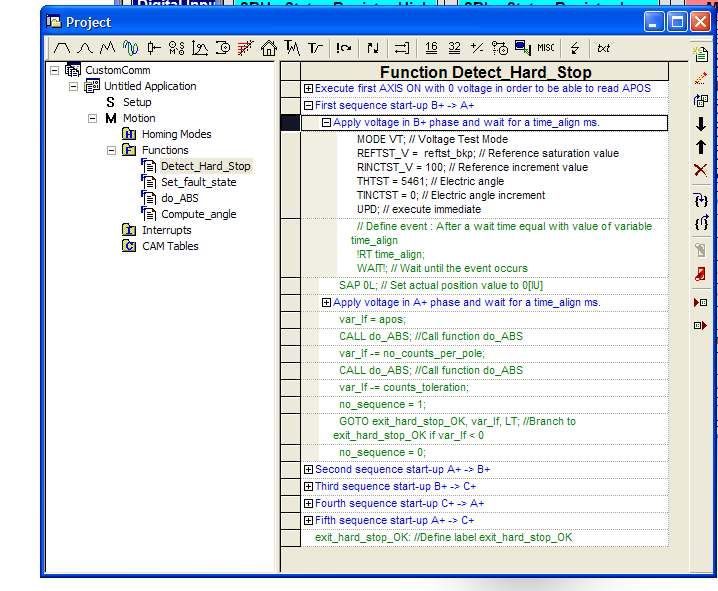
Effect of the PID Terms                         and actual current respectively (which
                                                are proportional to torque).
Rather then discuss control theory and
mathematical models, let us take a look         Clearly, the response is very sluggish.
at a practical tuning exercise and take a       After increasing the proportional gain a
closer look at the real effect of the           few times, we can get to the following
various gains. We will use a digital servo      result:
drive and motor with encoder feedback
to illustrate the effects of the various
gains, as well as provide some practical
guidelines.

One of the best ways to evaluate PID
tuning, is to look at the step response of
a system. In order to make sure we do
not saturate the system (and hence
avoid strong non-linearities), we will use
small signal response characteristics. In
addition to looking at the position
response, we will also look at the
torque, as a measure of “how hard we
are trying”.

Below is a picture of the response with
just a small proportional gain value. The       This particular system has almost no
integral and derivative gains are set to        friction. Notice the large overshoot, even
zero:                                           though the gain is relatively small. If we
                                                add friction to this system, then after
                                                increasing the proportional gain we get:

The red curve is the step reference. The
yellow line is position feedback. The
blue and green curves are reference

WWW.MOTION-DESIGNS.COM                (805) 504-6177                              PAGE   2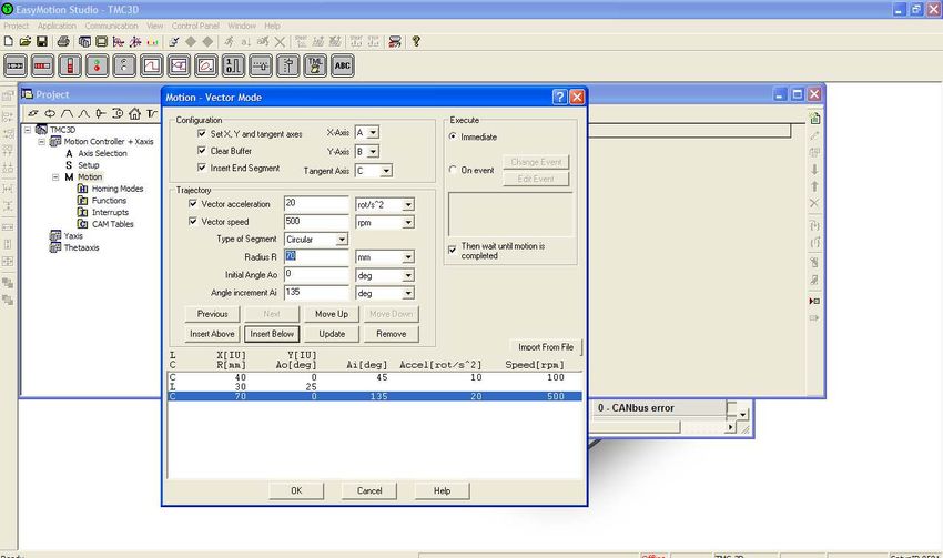
The additional friction helps dampen the
response, but of course a larger gain          Clearly, the large overshoot is
value is required. Also notice that the        eliminated.    However,     the     overall
final target is not quite reached (i.e.        response is also slower (meaning the
there is a small steady state error).          time required to reach the target).

This should always be the first step in        Frictional System – Effect of Integral
servo loop tuning. Start with just             Term
proportional gain and look at the
response. If the system has a tendency         As was noted, by just using a
to overshoot quickly, even with small          proportional term, a stable response can
gain, likely the friction is low. If more      be obtained, however the final target is
gain is required to get any response,          not reached. Because the integral term
and the response is slow, the system           integrates (i.e. accumulates) the error,
has      considerable     friction.  This      the longer the error exists, the larger the
determines the next step.                      integral will become, resulting in a
                                               correction torque. In the system above,
Low Friction System – Effect of                with the same proportional gain, we
Derivative Term                                have added integral gain:

In a low friction system, the response
has a tendency to become unstable
quickly, even with low gains. To remedy
this instability, derivative action is
required.    Because      the    D   term
differentiates the position error - which
changes fast in case of instability - it
helps suppress the large changes by
creating an opposing torque. In the
system      above,   with     the   same
proportional gain, we have added some
derivative gain:

                                               Notice how the steady state error was
                                               forced to zero. Also notice that we
                                               implemented an Integral Limit (a.k.a.
                                               anti-windup). This limit is required to
                                               avoid the integration from becoming too
                                               large and taking too long to converge
                                               down.

WWW.MOTION-DESIGNS.COM               (805) 504-6177                              PAGE   3
PID Combined                                          Settling time: after how much
                                                      time is the position settled within
One can notice that in case of the P and              some % of the target.
D terms in a low friction system that the
steady state error is non-zero. Also in        For example, in the response below:
case of the P and I terms in a frictional
system, some overshoot is introduced.
Of course in those cases we can add
integral    and      derivative    terms
respectively. For example, after adding
some derivative gain to the frictional
system one obtains the following
response:

                                               The overshoot is about (0.42-0.25)/0.25
                                               = 0.68, i.e. 68%. The response time is
                                               about 25 milliseconds. The settling time
                                               is about 200 milliseconds. These
                                               performance indexes are ultimately
                                               related to the system bandwidth.

                                               As all the gains are gradually increased
                                               to obtain the desired response, some
                                               additional effects may occur:
                                                  Saturation: one can run into current,
                                                  torque or voltage limitation, which
                                                  creates a strong non-linearity
                                                  typically resulting in overshoot and
                                                  instability.
Tuning Trade-offs                                 Resonance: as the system gets
                                                  excited at higher frequencies and
So far we have looked at the effect of            power, system resonance may affect
each term on the response curve, in               system response in unpredictable
order to show how they contribute. From           ways.
the response curves one can clearly see           Jitter: higher gains will cause small
that in addition to the shape of the              changes in the feedback to cause
response, the response time is                    large jumps in currents. This leads to
dramatically affected. Response curves            jitter (small oscillations at standstill).
have a few attributes that help quantify
the response:                                  For example, below is the system
       Overshoot: by how much is the           response as we keep increasing the
       target position exceeded.               gains to obtain faster response:
       Response time: after how much
       time is 67% of the final target
       reached.

WWW.MOTION-DESIGNS.COM               (805) 504-6177                                PAGE   4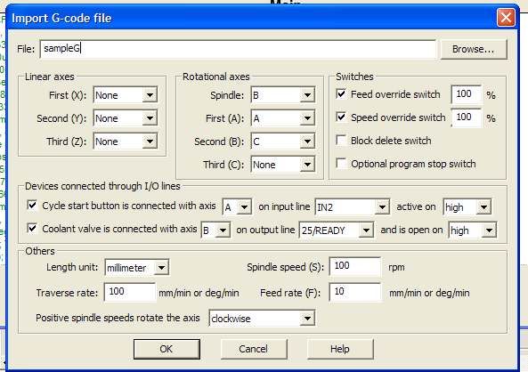
requirements but     also   on   desired
                                               system response.

                                               In Conclusion

                                               Servo loop tuning is not a trivial task.
                                               There is no denying that hands-on
                                               experience is invaluable. Although the
                                               behavior of the PID algorithm is well
The current limit in our system is             understood,      there    are     many
reached at 4A. Reaching this limit             implementation details and system
causes saturation and an ensuing               parameters that influence the response.
oscillation (which does die out after          By utilizing a systematic approach of
coming out of saturation).                     increasing the proper gains gradually
                                               while monitoring the response, stable
This means that motor and drive sizing         behavior can be more quickly obtained.
should not only be based on the torque         In parallel, one should also observe
and speed requirements, but also on the        current and torque to determine how
required system response. Mechanical           much power is applied, or to avoid
transmission components should also            saturation. If the system is marginally
be carefully selected to avoid system          sized, it may be necessary to adjust
resonance (see previous article on the         performance expectations.
effect of coupling stiffness). Lastly the
feedback resolution should not just be         Lastly, one must of course have the
based     on    positioning    resolution      proper tools to perform this exercise.

WWW.MOTION-DESIGNS.COM               (805) 504-6177                             PAGE   5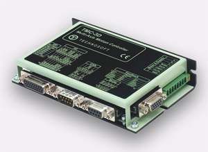
Technosoft TMC-3D Multi-Axis Controller
With Integrated Drive

The TMC-3D combines a multi-axis motion
controller and single axis drive in a single
compact unit. As a controller, the TMC-3D
can command 8 Technosoft drives via the
CAN bus. In addition to 3D and 2D
contouring, a G-code interpreter can translate
CAD data to motion commands.

      8-axis controller
      Linear and circular interpolation
      Vector speed and acceleration
      Axis management and synchronization via CAN bus
      Any axis can be any Technosoft drive (mix steppers and servos)
      Built-in drive suitable for servo or stepper motor, up to 80VDC, 16A peak.

Programming the controller is done via EasyMotion Studio, a powerful graphical
interface for setup and tuning.

WWW.MOTION-DESIGNS.COM               (805) 504-6177                                PAGE   6
Product Feature: Arcus LabView VI’s

Introduction

Arcus Technology takes advantage of the easy-to-use and convenient attributes of USB
communication to bring stepper motion control to the everyday user. Arcus provides 1-
4 axes controllers with various specifications and integration packages.

Because of LabView’s popularity in the automation industry Arcus has created an API
and an example application that is fully compatible with the programming platform.
Communication is established via LabView VI’s (Virtual Instruments) which in turn
access a dynamic link library (DLL) named “PerformaxCom.dll”. This DLL contains
functions which are specific to the Arcus USB protocol.

Note: All LabView VI’s as well as the generic software GUI were written using National
Instrument LabView version 8.5.

USB Driver

Before getting started the Arcus USB driver must be installed. This will install the
necessary driver files for USB detection and communication when Arcus USB products
are connected to the PC.

Arcus LabView VI’s

Arcus LabView VI’s are the basic blocks used for USB communication. See below for a
list of the VI’s that Arcus provides:

  #   VI Name                          Function Description
  1   fnPerformaxMove.vi               Move the axis(axes)
  2   fnPerformaxSpeedAccel.vi         Set speed and acceleration settings for the controller
  3   fnPerformaxIO.vi                 Controls the inputs/outputs of the controller

WWW.MOTION-DESIGNS.COM               (805) 504-6177                                      PAGE   7
Get the controller motor status (idle, in motion, error
4 fnPerformaxMotorStat.vi
state, etc.)
Set miscellaneous parameters (e.g. polarity, triggers,
5 fnPerformaxGeneral.vi
etc…)
Send/Receive raw ASCII commands. Note: The Arcus
6 fnPerformaxCommandReply.vi USB protocol is ASCII based. VI’s 1-6 are wrappers
around the ASCII based protocol.
Get the total # of Arcus USB devices connected to the
7 fnPerformaxComGetNumDevices.vi
PC
This function is used to get the Performax product
string. This function is used to find out Performax USB
8 fnPerformaxComGetProductString.vi
module product string and its associated index
number. Index number starts from 0.
9 fnPerformaxComOpen.vi Open a USB communication handle.
10 fnPerformaxComClose.vi Close a USB communication handle.
Set the read/write time-outs for the USB
11 fnPerformaxComSetTimeouts.vi
communication
Below is a block diagram view of a sample usage of fnPerformaxMove.vi
fnPerformaxMove.vi
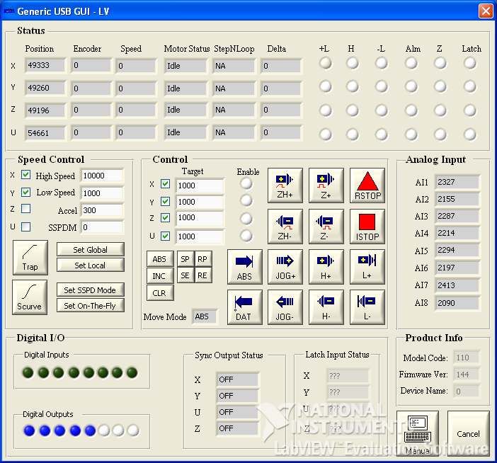
WWW.MOTION-DESIGNS.COM (805) 504-6177 PAGE 8Generic GUI A generic GUI (with source code) is provided to show an example of how to use the USB VI’s. Note that this generic GUI can be used with any Arcus USB product. Upon USB connection the software will automatically determine which functions to allow and disallow depending on the USB controller model. Below is a screen shot of the application. WWW.MOTION-DESIGNS.COM (805) 504-6177 PAGE 9
Application Solution: Lab Automation Gripper with IBL2403

Introduction                                    possible to build a completely custom
                                                commutation mechanism. The concept
Lab automation systems often require            is as follows:
precise control of a gripper to                     1. Set an output voltage vector at a
manipulate micro plates. A particular                   particular angle and allow the
implementation of such a gripper uses a                 rotor to align itself
brushless rotary servo motor with                   2. Record the position after a
integrated lead screw and incremental                   configurable settling time
rotary      encoder.     Although     this          3. Set an output voltage vector at
configuration is mechanically and                       another angle
electrically very elegant, it did provide           4. Record the new position after
some challenges:                                        settling
    • Brushless motor commutation                   5. Verify if the amount of motion
        with incremental encoder only                   corresponds to the proper
    • Commutation startup at end of                     theoretical amount
        travel                                      6. If the position difference is
    • Commutation startup with micro                    outside an acceptable window,
        plate being held                                re-start at step 3 (at yet another
                                                        angle).
The Technosoft IBL2403 provides the
proper flexibility to address this fairly       This sequence “steps” the motor
complex task in a safe manner.                  through a controllable sequence, and
                                                ensures that the proper motion has
Motor Setup                                     been detected. If a hard-stop does not
                                                allow the motor to align itself, the
The brushless motor is a 6-pole motor           expected amount of motion will not be
with integrated 300 lines per revolution        reached, and a new vector angle can be
encoder (i.e. 1200 counts). In addition to      attempted. Since rotor alignment means
the low encoder count per electrical            seeking a null torque position, a hard-
cycle, the ability to commutate against a       stop could create a false-positive, hence
physical stop made the use of a typical         the position measurement serves as an
phase finding routine impossible.               integrity check that the motor has
                                                moved the proper amount of electrical
Because the Technosoft controllers              degrees.
have a built-in voltage test mode, it was

Programming

Technosoft’s EasyMotion Studio makes programming very straightforward, through the
Motion Wizard window. All aspects of the commutation routine are implemented via
functions in order to keep flexibility and modularity. Four functions are created:

WWW.MOTION-DESIGNS.COM                (805) 504-6177                              PAGE   10
The Detect_Hard_Stop function sequences through various electrical angles and checks the amount of motion, Set_fault_state sets a fault state in case the overall routine never detects proper motion, do_ABS calculates the absolute value of the position change, and Compute_angle computes the correct initial commutation angle. Most of the work is done in the Detect_Hard_Stop function: At the heart of this function is the ability to output a voltage at any angle: Each step within this function positions the output vector at a different angle (an angle that corresponds to 2 of the 3 phases being activated). By setting the vector angle at 60 degree intervals, any phase pair can be activated. Moreover, any phase-pair sequence can be created. By carefully selecting the order in which each phase-pair is energized, it WWW.MOTION-DESIGNS.COM (805) 504-6177 PAGE 11
is possible to “back away” from a hard stop condition, and find the proper commutation
angle.

In order to accommodate any motor and feedback, the following variables have been
created that are used by the routine:

   •   Pole_pairs – number of electrical cycles (3 in case of a 6-pole motor)
   •   Refttst_bkp – output voltage level
   •   Nenc_counts – number of encoder counts (here 1200)
   •   Time_align – settling time for each new voltage vector
   •   No_counts_per_pole – number of counts per 120 electrical degrees (here 133 =
       1200/3/3)
   •   Counts_tolerance – allowed deviation between measured position change and
       expected position change

The routine also tracks the number of sequences required until a valid number of counts
was found.

WWW.MOTION-DESIGNS.COM               (805) 504-6177                            PAGE   12
For more information about any of the above topics or general questions or comments,
please contact us:
Motion Designs
contact@motion-designs.com
Tel 805.504.6177
Motion Designs is a technical sales and engineering company with extensive machine and motion
control experience. We work with some of the best manufacturers in the industry as witnessed by
our present line card:
www.arcus-technology.com: Arcus Technology manufactures stepper motor, drive and
controller technology, providing USB, Ethernet and Mod-Bus connectivity.
www.nipponpulse.com: Nippon Pulse manufactures the unique linear shaft motor, a direct
drive linear brushless servo motor.
www.shinano.com: Shinano Kenshi manufacturers cost effective brushless servo motors and
assemblies.
www.stegmann.com : Stegmann is a leader in high performance motor feedback solutions.
www.technosoftmotion.com : TSM is a leading DSP motion control technology company
specializing in the development, design and manufacturing of digital motor drive products and
custom motion systems.
WWW.MOTION-DESIGNS.COM (805) 504-6177 PAGE 13You can also read