ELECTRIC BOILER 6, 9 & 12kW - INSTALLATION AND USER GUIDE - PLEASE RETAIN FOR REFERENCE - Advance Appliances
←
→
Page content transcription
If your browser does not render page correctly, please read the page content below
ISSUE 2
                                 0121

INSTALLATION AND
   USER GUIDE

  6, 9 & 12kW
ELECTRIC BOILER

PLEASE RETAIN FOR REFERENCE
INTRODUCTION
Please read and understand these instructions prior to installation and commissioning.
These instructions should be left with the customer once the unit is commissioned and
running satisfactorily.
The boiler is available in three output versions, 6kW, 9kW and 12kW and can be specified
for standard central heating circuits with an 80 degree flow or underfloor circuits with a
60 degree flow.
The unit is intended for domestic central heating systems and can be connected to single
phase domestic electricity supplies, please see the Technical Specification for more
information.
Advance eGlow boilers are compact and quiet in operation, require no fluing and can be
located anywhere within the property. A pump is fitted in the eGlow making installation
very straight forward. The pump has an over run facility and there is an automatic by pass
fitted. The eGlow should be installed as a sealed system boiler. A sealed system kit is
available for easy installation with an 8 litre expansion vessel. This can be sited anywhere
in the circuit giving the installer flexibility.
The eGlow is controlled externally with a programmer and room thermostat arrangement
with voltage free switching (not supplied). There is a connector in the boiler casing for
this purpose. Standard central heating programmers and room thermostats can be used.
The boiler is fully modulating and soft switched on start up. This enhances the life of the
heat exchangers as well as reducing the loading on domestic electricity. A single LED
highlights running and fault modes.
A flow switch prevents the boiler running in dry conditions and there are two levels of
overheat protection.
The Advance eGlow boiler is guaranteed for two years against faulty manufacture, subject
to terms and conditions, and a technical help desk service is offered during office hours.
The unit requires no maintenance in ordinary operating conditions. Stainless steel heat
exchangers are fitted for long life and reliability.

 PRODUCT CODES

CODE       TYPE                                   SIZE                  WEIGHT FULL KG
EG6        6KW CENTRAL HEATING BOILER             510h x 400w x 167d    15KG
EG6-U      6KW UNDERFLOOR HEATING BOILER          510h x 400w x 167d    15KG
EG9        9KW CENTRAL HEATING BOILER             510h x 400w x 167d    15KG
EG9-U      9KW UNDERFLOOR HEATING BOILER          510h x 400w x 167d    15KG
EG12       9KW CENTRAL HEATING BOILER             510h x 400w x 167d    15KG
EG12-U     9KW UNDERFLOOR HEATING BOILER          510h x 400w x 167d    15KG

                                             2
OPTIONAL SEALED SYSTEM KIT AA 0400
KIT INCLUDES:
COLD FILL HOUSE WITH DOUBLE ISOLATION
3 BAR PRESSURE RELIEF VALVE 1/2”
EXPANSION VESSEL 8 LITRES
PRESSURE GAUGE
TECHNICAL SPECIFICATIONS
POWER RATING 6kW 9kW 12kW
FLOW AND RETURN 22MM BOTTOM ENTRY 22MM BOTTOM ENTRY 22MM BOTTOM ENTRY
ELECTRICAL SUPPLY SP 240 VAC 50hz 30A SP 240 VAC 50hz 40A SP 240 VAC 50hz 50A
PROTECTION 32 AMPS 45 AMPS 63 AMPS
PUMP 15/50 15/50 15/50
PUMP SETTING AUTO AUTO AUTO
OUTPUT TEMP (MAX) 80°C 80°C 80°C
UNDERFLOOR UNITS
OUTPUT TEMP (MAX) 60°C 60°C 60°C
HIGH LIMIT TEMP
CONTROL 2 STAGE 90°/95°C 90°/95°C 90°/95°C
NOM HEAT OUTPUT 20,000 BTU 30,000 BTU 40,000 BTU
AUTO AIR VENT FITTED FITTED FITTED
FLOW SWITCH FITTED FITTED FITTED
AUTO BY PASS FITTED FITTED FITTED
MIN PRESSURE COLD FILL 0.6 BAR 0.6 BAR 0.6 BAR
MAX PRESSURE HOT 3 BAR 3 BAR 3 BAR
HEAT EXCHANGERS STAINLESS STEEL STAINLESS STEEL STAINLESS STEEL
3Kw PODS x 2 3Kw PODS x 3 3Kw PODS x 4
IPX RATING 1 1 1
3MOUNTING THE BOILER
Please ensure that all current local by laws and national building regulations are consulted
prior to installation along with current codes of practice.
The unit must be mounted in a vertical position accessible for servicing. Effectively this
means allowing front facing access to remove the outer door casing to access the eGlow.
Please check load bearing and ensure correct fixing is used. There are four holes in the
casing for this purpose.
The 22mm flow and return pipes are at the bottom of the boiler, and should be connected
using compression fittings. Do not solder connections within 600mm of the boiler. Flow is
the left pipe, marked red, return is the right pipe, marked blue. We suggest you install the
means to isolate and drain the boiler independently.
SAFETY
No special precautions are required, however due care should be taken in installing,
commissioning and servicing to prevent electric shock or water leakage.
INSTALLATION
Only persons competent to do so may fit this appliance.
Calculate space heating requirements and allow an extra 3kW for hot water provision if
an indirect cylinder is to be installed. Advance recommend an Advance Appliances stainless
steel pre-plumbed unvented cylinder and would always advise customers to consider
renewable energy such as solar to contribute toward the generation of domestic hot water.
Using a direct (electric) Advance Appliances unvented cylinder will reduce installation cost.
Controls such as room thermostats and programmers or timers must be installed to
comply with current Part L requirements.
Ensure that the correct appliance is fitted, for example by sizing to meet demand and by
choosing underfloor or central heating models.
The system must be properly flushed and have inhibitor added according to manufacturer’s
specifications. Always choose a recognised brand and inhibit to the correct dilution. Always
flush out completely as any chlorine based chemicals can attack stainless steel components.
After drain down, even a partial one, inhibitor levels must be topped up.
Y, W or S plan systems may be used with the eGlow.
Primary pipe work in enclosed spaces such as boiler cupboards should be insulated. Fit
isolation valves.
It is important to have a locked open radiator or open towel rail in the system.
Thermostatic radiator valves are recommended. Use a twin pipe 22mm system with 15mm
tee off to radiators.
4INSTALLATION SCHEMATICS
SEALED SYSTEM
Sealed System Kits are available from
Advance Appliances and can be sited
anywhere in the open pipework of eGlow Boiler
the system
Guage
Expansion RETURN
Vessel
Filling Loop FLOW
3 Bar Expansion Valve
The eGlow boiler can only be configured into a sealed system. A sealed system kit can be
purchased from Advance Appliances to make the job simple. An 8 litre expansion vessel is
supplied with each kit but it should be noted that systems with high water content may
require larger vessels. All heating systems must be isolated from the mains water supply
after the system is filled.
ELECTRICAL CONNECTIONS
THIS APPLIANCE MUST BE EARTHED
The appropriate current regulations and best practices must always be followed. Installation
must be carried out by a competent and qualified tradesman. Use off peak supplies where
possible to reduce running costs.
Check the incoming supply meets the minimum requirements of the appliance and utilise
a double pole RCD capable of breaking the full current load. Remember that the full house
loading must be taken into consideration when calculating mains demand. Refer to IEE
regulations for wiring size to the appliance. The mains feed goes directly to the terminal
block identified on the schematic (on page 8) and the boiler itself. The earth must be
connected to the marked point.
Standard switching is maintained through the controls, zero voltage switching is used and
a separate power supply for programmer and room thermostat (if digital) should be used.
In some cases this may be a battery or a mains charger with rechargeable cells in the
programmer. This control circuit is identified on the schematic (on page 8) and will switch
the boiler internally.
In the case of a combined hot water and heating system a Y plan or similar can be used
with a three port motorised valve, in which case a separate mains supply will be required
to operate the valve which will be switched via a suitable programmer NOT the boiler
PCB. Use a relay if any voltage is present.
Always consult manufacturer’s requirements and recommendations for controls, the above
advice is of a general nature only.
5ELECTRICAL CONNECTIONS continued
Check after installation
• Polarity
• Short circuit
• Earth continuity
• Resistance to earth
• Visual check for stray wiring strands etc
• Mechanical check for integrity of connections
Do not switch on until the unit is full of water and air has been purged from the system.
IMPORTANT
The switching in the boiler is zero voltage and cannot be used for mains switching e.g. three
port valves.
We recommend hot water is provided by an independent electric/solar cylinder for
optimum efficiency.
COMMISSIONING
Fill the system by opening isolating valves to the feed and expansion tank or to the filling
loop of a sealed system. Charge sealed systems from 0.75 bar to 1 bar.
When the system is full, and has been thoroughly checked for leaks it should be flushed
out to remove any debris.
Refill, add system cleanser and switch on the boiler.
The boiler controls are fully automatic. The LED will turn green showing that the boiler is
powered up and awaiting demand. When heating demand is on (set the programmer and
room thermostat to call for demand) the pump will be energised for 5 seconds in order
for the flow switch to sense flow in the boiler. If it does not sense flow the boiler will
switch off, the LED will show red (continuously) indicating that the circuit contains air (no
flow).
Check that all air is purged and try again. The boiler can be switched back on again by
turning the programmer/room thermostat off and on. It is usual for this process to take a
little time in all heating circuits.
TIP:
Run the boiler with pods disconnected until air is purged. You may need to increase the
pump speed to do this.
NEVER link the flow switch out – it is dangerous and will damage the heater pods. This
action will void guarantees.
Allow the boiler to run for 30 minutes to ensure that it is operating correctly and flush
again.
6USER INSTRUCTIONS
Set the programmer to match your own preferences for heating periods. The room
thermostat should be set at a comfort level, usually 20°C. The room thermostat should be
in a room where the radiator is locked on e.g. a hallway, study etc rather that a living room
or bedroom. The boiler is automatic and should give a trouble free life.
The green LED means that there is power to the boiler; it doesn’t mean that the boiler is
actually heating the system. It does this when there is demand for heating through the
programmer and room thermostat.
If there is insufficient water in the system the red LED will be on continuously. Switch the
room thermostat off and on (making sure that the programmer is on) to start the boiler
up again, air may be present in the system. If the fault persists the system may need
recharging – consult your installer.
The case can be kept clean with a damp cloth.
FAILURE
The LED may flash red, indicating overheat. The unit is protected by the PCB controller in
addition to a thermomechanical device. The appliance will reset itself when it cools. If the
overheat recurs please ensure that the connection from the thermistor (on page 8) to the
PCB is soundly made. Check circulation is free in your heating system. A continuous red
LED relates to a no flow condition and air must be purged from the heating circuit or low
pressure, please charge system. Consult problem solving on page 9 if failure persists.
PROTECTION
In situations where this appliance may be subject to temperatures below 5°C (e.g. holiday
lets not occupied in winter etc) a frost thermostat can be linked to the control circuit. The
unit should always be installed in the main envelope of the property, never outside.
The eGlow can be safely installed in most situations, however, excessive moisture or
temperature extremes should be avoided.
PART NUMBERS
3Kw HEATER PODS AA0401
PCB ASSEMBLY AA0402
FLOW SWITCH AA0403
AUTO AIR VENT AA0404
AUTO BY PASS AA0405
THERMISTOR AA0406
PUMP AA0407
CONTACTOR AA0408
HIGH LIMIT THERMOSTAT AA0409
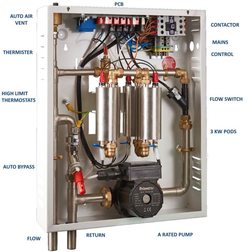
7SCHEMATIC
PCB
AUTO AIR
VENT CONTACTOR
MAINS
THERMISTER CONTROL
HIGH LIMIT
THERMOSTATS FLOW SWITCH
3 KW PODS
AUTO BYPASS
RETURN A RATED PUMP
FLOW
8EGLOW PROBLEM SOLVING
Note: Main fault modes LED7 Red Cont – Flow Switch
Red Flashing – overheat Green – All ok
Check voltage input at the terminal is between 207v-
245v. Note voltage during commissioning should be
checked when the pods are acve to ensure the voltage
does not go below the minimum level.
Go back to source and
Yes No check wiring
Check voltage input R/H
contactor
Yes No Faulty wires from block to
contactor
Check ZERO voltage demand and
switch on. Contactor should
switch on
Yes No Check the wires from the
demand terminal to the board. If
ok replace contactor
LED 6 lit on PCB
Yes No Check fuse 3.15A fast
acng 20 mm
Check for 12v D.C as below
Yes No Replace board
9EGLOW PROBLEM SOLVING continued
Check connuity on
buon stat(s) on pods 2
Yes No Replace buon stat(s)
Is the pump running?
Yes No Check voltage to pump
No Power
Power
Replace Replace
board pump
Test flow switch with the pump
running, there should be
connuity
Ensure system is fully purged
Yes No of air. If yes, replace flow
switch
Disconnect all pods, check for connuity
across terminals, check resistances are 18-21Ω
and check for earth leakages between the pod
terminal and pod case
Replace pod
Yes No
Disconnect all pods. Turn on the boiler. Check
each of the pod leads in pairs for power – note
that the pods come on in sequences, not all at
once
Replace board
Yes No
10EGLOW PROBLEM SOLVING continued
Connect each pod in turn.
Does any one pod, when
connected, turn off the boiler?
Yes Replace pod
Notes
LED layout Contactor
Diagram Pump
Green: ON
Red: off but board powered
Pods 1 to 4
Fault: Red Cont= Flow
Red Flash= Overheat
Mode SW1 SW2 SW3 SW4
Central heang Off X X X
Under floor On X X X
3KW X Off Off X
6KW X Off On X
9KW X On Off X
12KW X On On X
Enable main contactor X X X On
Disable main contactor X X X Off
X = Any posion
TO CHECK INDIVIDUAL PODS MAKE SURE THERE IS CONTINUITY ACROSS THE TERMINALS AND
THAT THE RESISTANCE IS 21 OHMS
11ADVANCE APPLIANCES GUARANTEE
The eGlow has been manufactured and tested to a high specification and should give years
of trouble free life. If it should go wrong you will be covered for a period of two years
from the date of installation provided that
• You keep proof of purchase/installation date
• Warranty is registered on Advance Appliances Website
• It is installed correctly and the benchmark paperwork is completed
• It is used for its intended purpose
• It is operated properly
• It has not been tampered with or altered in any other way (for example removing the
caps on flow switches)
The foregoing does not affect your statutory rights.
UNIT 4 COPPICE SIDE IND EST BROWNHILLS WALSALL WS8 7EX TEL 01543 377723
For Terms and Conditions go to www.advanceappliances.co.uk
12You can also read