FELIX: the Detector Interface for the ATLAS Experiment at CERN
←
→
Page content transcription
If your browser does not render page correctly, please read the page content below
EPJ Web of Conferences 251, 04006 (2021)                                 https://doi.org/10.1051/epjconf/202125104006
CHEP 2021

      FELIX: the Detector Interface for the ATLAS
      Experiment at CERN

      Alexander Paramonov1 on behalf of the ATLAS TDAQ Collaboration
      1
       Argonne National Laboratory, Lemont, Illinois, USA

                    Abstract. The Front-End Link eXchange (FELIX) system is an interface
                    between the trigger and detector electronics and commodity switched
                    networks for the ATLAS experiment at CERN. In preparation for the LHC
                    Run 3, to start in 2022, the system is being installed to read out the new
                    electromagnetic calorimeter, calorimeter trigger, and muon components
                    being installed as part of the ongoing ATLAS upgrade programme. The
                    detector and trigger electronic systems are largely custom and fully
                    synchronous with respect to the 40.08 MHz clock of the Large Hadron
                    Collider (LHC). The FELIX system uses FPGAs on server-hosted PCIe
                    boards to pass data between custom data links connected to the detector
                    and trigger electronics and host system memory over a PCIe interface then
                    route data to network clients, such as the Software Readout Drivers (SW
                    ROD), via a dedicated software platform running on these machines. The
                    SW RODs build event fragments, buffer data, perform detector-specific
                    processing and provide data for the ATLAS High Level Trigger. The
                    FELIX approach takes advantage of modern FPGAs and commodity
                    computing to reduce the system complexity and effort needed to support
                    data acquisition systems in comparison to previous designs. Future
                    upgrades of the experiment will introduce FELIX to read out all other
                    detector components.

      1 Introduction
      The ATLAS experiment at CERN [1] explores collisions of protons and heavy ions from
      the Large Hadron Collider (LHC) to study physics at the energy frontier. The LHC
      accelerates bunches of particles to up to 6.5 TeV and collides them every 25 ns at a
      combined energy up to 13 TeV. It is therefore imperative for the on-detector electronics
      systems to run synchronously with the LHC clock to digitize the detector signals. The
      detector electronics systems use custom synchronous serial data links to read out data. The
      Front-End Link eXchange (FELIX) system serves as an interface between these links and
      commodity switched networks.

          FELIX is installed alongside the existing legacy readout system (ROD and ROS [2] [3])
      to readout the electromagnetic (liquid Ar) calorimeters [4], Level-1 calorimeter trigger
      system [5] and selected muon systems (BIS 7-8 [6] and New Small Wheels [5]) as shown in
      Fig. 1. The next upgrade stage will take place before LHC Run 4. It will allow ATLAS to

© The Authors, published by EDP Sciences. This is an open access article distributed under the terms of the Creative Commons
Attribution License 4.0 (http://creativecommons.org/licenses/by/4.0/).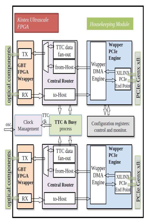
EPJ Web of Conferences 251, 04006 (2021)                      https://doi.org/10.1051/epjconf/202125104006
CHEP 2021

      observe and record collisions at a much higher intensity after the upgrade of the LHC for
      the High Luminosity program. By Run 4, the FELIX system will be installed to read out all
      detector components.

      Fig. 1. Present architecture of the ATLAS data acquisition system. FE represents a detector
      readout system.

          To reduce the data rates, the ATLAS trigger system inspects data from every bunch
      crossing and filters only bunch crossings of interest. Only 1 out of about 40,000 bunch
      crossings are useful for further processing and stored to disc. The trigger system operates
      with small and deterministic latency. The trigger passes its decisions to FELIX and it
      distributes them to the detector readout electronics. The detector readout electronics buffers
      data while the first level (level-1) hardware trigger system is analyzing it. Currently, the
      trigger rate is limited to 100 kHz, rising to 1 MHz for the high-luminosity programme in
      Run 4.

          The FELIX system consists of commodity servers with PCIe FELIX cards. A FELIX
      card contains an FPGA interfaced to the PCI express bus and fiber-optic transceivers. One
      of the optical links receives a serial bitstream from the Timing, Trigger and Control (TTC)
      system. The TTC system transmits the trigger decisions and LHC-related signals (such as
      the clock). The other optical links are connected to the detector readout systems, able to
      operate in a bi-directional manner. The TTC and to-detector links use custom fully-
      synchronous data transmission protocols. The FPGA allows us to handle data transmissions
      and to route data between the detector links and the PCIe interface. FELIX software routes
      data between the FELIX cards and the switched network (e.g. Ethernet).

         The FELIX approach was facilitated by the rapid development of commodity switched
      networks, server CPUs and FPGAs. FELIX reduced the need to develop custom electronics
      and firmware in comparison to the previous data acquisition architecture. The commercial

                                                    2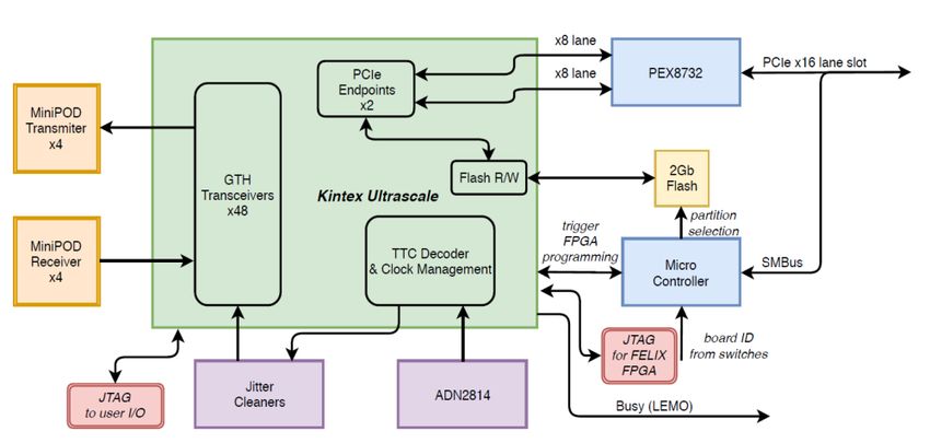
EPJ Web of Conferences 251, 04006 (2021) https://doi.org/10.1051/epjconf/202125104006
CHEP 2021
components (e.g network interface cards, servers, network switches) can be easily
maintained, upgraded, and customized to meet the needs of the experiment. FELIX’s
utilization of a switched network also simplifies the software design.
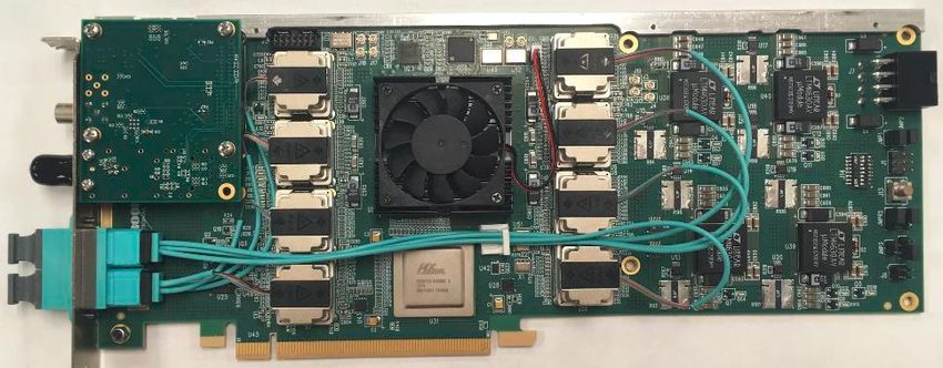
2 FELIX I/O card
The FELIX card, also known as FLX-712, is a custom-designed standard PCIe card with a
16-lane PCIe Gen3 interface as shown in Fig. 2. The card features a Xilinx Ultrascale
FPGA, XCKU115-FLV-1924, and 8 Avago Minipod transceivers (4 TX and 4 RX). The
FPGA has two 8-lane PCIe interfaces, one per super logic region. The card also includes a
mezzanine card for the TTC link and a BUSY output. The optical links can operate at
speeds up to 12.8 Gbps. The BUSY output is connected to the TTC system to make it
possible to inhibit the operation of the ATLAS central trigger through a dedicated signal.
Fig. 2. FELIX PCIe card, FLX712.
A functional diagram for the board components is shown in Fig. 3. The PCIe switch
PEX8732 interfaces the 16-lane PCIe slot and the 8-lane FPGA endpoints. The jitter
cleaners are needed to provide reference clocks to the Multi-Gigabit GTH Transceivers
(MGTs). The ADN2814 IC digitizes the TTC signal as a 160 Mb/s bitstream and also
provides a recovered clock. The FPGA can be programmed via a JTAG connector or PCIe.
The 4 TX and 4 RX minipods offer 48 bi-directional links aggregated into two MTP48
couplers.
3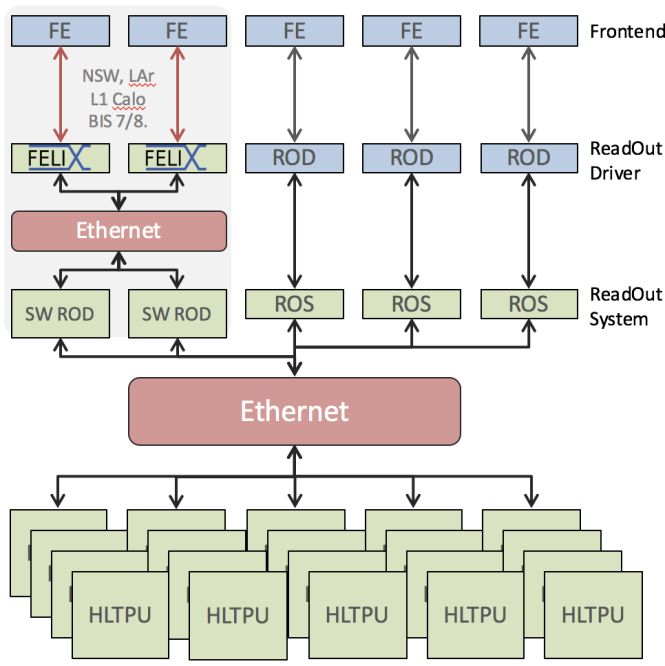
EPJ Web of Conferences 251, 04006 (2021)                    https://doi.org/10.1051/epjconf/202125104006
CHEP 2021

      Fig. 3. Functional diagram of FLX-712 components.

          The hardware platform has been extensively tested and verified. The throughput of the
      PCIe interface was measured to be about 100 Gb/s, in agreement with the specifications.
      The optical links were characterized for 9.6 and 12.8 Gb/s and the bit-error rates were
      measured to be less than 10-15 for each of the 48 links. The power consumption of the board
      is at most 65 W and the FPGA temperature does not exceed 70 C when housed in the final
      server configuration to be used on ATLAS Run 3. After completing the verification, 255
      FLX-712 boards were produced for the ongoing upgrade and other R&D needs.

          A prototype FELIX board for the Run 4 upgrade has also been designed. It features a
      Xilinx Versal Prime FPGA and 24 optical data links. The board has a 16-lane PCIe Gen 4
      interface. The optical links may support data rates up to 25 Gb/s. A final decision on the
      hardware platform won’t be made for some time, but ongoing studies with this prototype
      and its successors will make it possible to closely track technological evolution.

      3 FELIX firmware
      All the serial data links from FELIX to the detector systems use the GBT protocol
      developed by CERN [8]. The GBT data frame contains 120 bits and the link speed is 4.8
      Gb/s to make each frame synchronous with the 40.08 MHz clock of the LHC. CERN has
      also developed a radiation-hard ASIC, GBTx, to aggregate and de-aggregate multiple
      slower serial links (E-links) into a GBT link. The input high-speed data links from the
      detector components to FELIX can also use the GBT protocol or a custom 8b/10b encoded
      protocol operating at 9.6 Gb/s called FULL Mode. The MGT transceivers with the GBT
      encoders and decoders are shown in Fig. 4.

                                                  4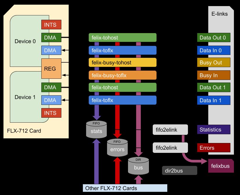
EPJ Web of Conferences 251, 04006 (2021)                        https://doi.org/10.1051/epjconf/202125104006
CHEP 2021

      Fig. 4. Functional diagram of FELIX firmware.

          The 40.08 MHz LHC clock is recovered from the TTC bitstream and the 160 MHz
      clock provided by the ADN2818 IC. The 40.08 MHz clock is then passed to the clock
      management block and to the external jitter cleaner ICs. The GBT wrappers, GTH
      transceivers, and the central router use the LHC clock and the clock from GTH transceivers
      (also derived from the LHC clock) to generate signals for the detector electronics. The card
      can also use a local oscillator to generate a 40.08 MHz clock during stand-alone operation
      (without the TTC system) outside of the ATLAS experiment.

          The TTC system transmits two bits for every LHC bunch crossing. The first bit is the
      trigger decision and the second bit is used as a serial link for the other signals such as Event
      Counter Reset, Bunch Counter Reset, and trigger type. The TTC signals are passed to the
      detector electronics using 8 bits in the GBT data frame. FELIX matches each trigger accept
      signal to a combination of bunch counter, orbit counter, trigger counter, trigger reset
      counter and trigger type. All this information is also passed to subscribed processes over
      the switched network for every accepted bunch crossing (level-1 trigger accept) via the
      PCIe interface.

         The BUSY mechanism is used to prevent data losses. Each front-end system may report
      a BUSY condition if needed due to internal buffers nearing overflow. The FELIX server
      may also report BUSY if any internal buffers are about to overflow. The logical OR of the
      BUSY signals is passed to the BUSY output of the board.

         Each of the two PCIe endpoints is serviced by a dedicated firmware engine, called
      Wupper. Each Wupper engine has a 256-bit wide FIFO transfer data to and from the
      Central Router module. The FIFOs are connected to Direct Memory Access (DMA)
                                                     5
EPJ Web of Conferences 251, 04006 (2021) https://doi.org/10.1051/epjconf/202125104006
CHEP 2021
interfaces. Each PCIe endpoint supports only 8 PCIe lanes because of a limitation of the
Xilinx PCIe Gen3 hard block. The external register map is then connected to each Wupper
engine. The registers are used to control and monitor the firmware from the software
domain.
The Central Routers pass data between the Wupper blocks and optical links. Some links
are serial streams so the data needs to be encoded and decoded accordingly. The Central
Router is highly configurable to allow flexible combinations of links and serial protocols
for every link.
The firmware has been extensively validated with internal and external data emulators
and is undergoing integration with the detector systems: LAr, NSW, BIS 7/8, and
calorimeter triggers.
Development of the FELIX firmware for the Run 4 upgrade is progressing rapidly. The
future firmware will need to support many more types of detector systems than the present
firmware and the lpGBT link protocol in addition to the GBT protocol. Decoders and
encoders for pixel and strip modules of the future inner tracker have been designed and are
undergoing validation and integration with detector prototypes. FELIX will also need to
interact with the new Local Trigger Interface (LTI) system to receive TTC data and to
report BUSY states.
4 FELIX software
The FELIX software includes drivers, low-level tools, test software and routing software
that run on the FELIX server. The low level tools are needed to control and configure the
FPGAs. The FELIX cards are accessed and controlled with drivers known as flx and
cmem_rcc. The flx driver provides access to the register map (and therefore control of the
card). The cmem_rcc driver allows applications to allocate large contiguous buffers in the
server memory for high-bandwidth access via DMA. The routing tool, known as felix-star,
distributes data between the buffers and subscribed applications via the network as shown
in Fig. 5. felix-star uses a single-thread asynchronous event loop architecture. These events
have non-blocking callback functions to process interrupts from the FL712, send and
receive data and handle file description. The subscribed applications use a library known as
NetIO-next to communicate with felix-star. NetIO-next can use POSIX sockets or libfabric.
RDMA over Converged Ethernet (RoCE) reduces the number of data copies to transfer
data, avoids context-switching by bypassing the kernel and does not use either source or
client CPU. The performance of felix-star has been tested and verified for the trigger rates
up to 200 kHz, with the rate limited by network bandwidth (currently 100 GbE). The level
or performance exceeds the requirements for Run 3 by a factor of 2.
6EPJ Web of Conferences 251, 04006 (2021) https://doi.org/10.1051/epjconf/202125104006
CHEP 2021
Fig. 5. Architecture of felix-star data routing tool.
A Software ReadOut Driver (SW ROD) [9] receives data from a few FELIX servers to
aggregate and format the data to serve it to the High Level Trigger (HLT). The incoming
data fragments are aggregated into a group (event) for each accepted bunch crossing. The
SW ROD application is a customizable framework that can support detector-specific
algorithms for event building and processing. The SW ROD needs to handle data from
particle collisions and detector-specific activities such as calibration runs. The SW ROD
application is designed as a number of independent components with simple interfaces to
interact between each other. The components receive data fragments, build events and
distribute the data to the HLT or other consumers.
The SW ROD architecture is optimized for high throughput processing. It is capable of
event building at rates exceeding 100 kHz while the input packet rate is up to 120 MHz.
The performance was limited by the network bandwidth, with three processing threads to
handle the data volume. SW ROD is being developed further to build events at a 1 MHz
rate for Run 4. The memory management was found to be a bottleneck for 1 MHz data
processing and a new memory management approach was introduced. With this
improvement, the SW ROD was shown to already be able to process a 1 MHz event rate for
selected link configurations.
5 Conclusions and Outlook
The FELIX data acquisition system for the ATLAS experiment bridges the custom fully
synchronous detector electronics and commodity computing. FELIX is being installed and
commissioned for the ongoing upgrade to start operation in 2022. About 100 FELIX cards
are installed into 60 servers and another 20 servers are set up to run SW ROD. FELIX
hardware, firmware, and software are evolving rapidly to meet the future needs and to
readout all components of the ATLAS experiment after the next upgrade at a 10 times
higher trigger rate.
Acknowledgements
7EPJ Web of Conferences 251, 04006 (2021) https://doi.org/10.1051/epjconf/202125104006
CHEP 2021
Argonne National Laboratory's work was supported by the U.S. Department of Energy,
Office of High Energy Physics, under contract DE-AC02-06CH11357.
References
[1] ATLAS Collaboration, "The ATLAS Experiment at the CERN Large Hadron
Collinder," Jinst, vol. 3, p. S08003, 2008.
[2] A. Gabrielli, "Commissioning of ROD boards for the entire ATLAS pixel detector,"
Journal of Instrumentation, vol. 13, no. 09, pp. T09 009-T09 009, 2018.
[3] ATLAS TDAQ Collaboration, "The ATLAS Data Acquisition and High Level
Triggersystem," JINST, vol. 11, no 6, p. P006008, 2016.
[4] M. Aleksa and others, "ATLAS Liquid Argon Calorimeter Phase-I Upgrade Technical
Design Report," CERN-LHCC-2013-017, 2013.
[5] ATLAS Collaboration, "Technical Design Report for Phase-I Upgrade of the ATLAS
TDAQ System," CERN-LHCC-2013-018, 2013.
[6] L. Massa, "The BIS78 Resistive Plate Chambers upgrade of the ATLAS Muon
Spectrometer for the LHC Run-3," JINST, vol. 15, no. 10, pp. C10026-C10026, 2020.
[7] B. Stelzer, "The New Small Wheel Upgrade Project of the ATLAS Experiment,"
Nuclear and Particle Physics Proceedings, vol. 273275, pp./ 1160-1165, 2016.
[8] P. Moreira, R. Ballabriga, S. Baron, S. Bonacini, O. Cobanoglu, F. Faccio, T. Fedorov,
R. Francisco, P. Gui, P. Hartin, K. Kloukinas, X. Llopart, A. Marchioro, C. Paillard, N.
Pinilla, K. Wyllie and B. Wu, "The GBT Project," Proc. Topical Workshop on
Electronics for Particle Physics, pp. 342-346, 2009.
[9] S. Kolos, "New software based readout driver for the ATLAS experiment," presented at
the 22nd IEEE Real Time Conference, Virtal, Vietnam, 2020.
8You can also read