Research on comprehensive load vibration test of electric vehicle motor controller unit
←
→
Page content transcription
If your browser does not render page correctly, please read the page content below
E3S Web of Conferences 260, 03002 (2021)                                 https://doi.org/10.1051/e3sconf/202126003002
AEPEE2021

      Research on comprehensive load vibration test
      of electric vehicle motor controller unit
      Zhibiao Yan1,2,*, Lingxiao Zhao1,2, and Huansheng Ma1,2
      1CATARC     Automotive Test Center (Tianjin) Co., Ltd, Tianjin 300300, China
      2China   Automotive Technology & Research Center Co., Ltd, Tianjin 300300, China

                    Abstract. In this article, the vibration test standards and general test
                    methods for electric vehicle motor control unit are introduced. New
                    vibration test conditions are proposed based on the vibration data collected
                    during the actual vehicle test. Using the vehicle output current data as the
                    electrical load of the motor controller unit, and the temperature cycle as the
                    environmental load, a comprehensive load vibration test method that
                    integrates the electrical load and the environmental load is proposed.
                    According to the test method, the equipment and test process of the
                    comprehensive on-load vibration test of environmental load are determined.
                    Summarized three important principles in the design of fixtures:
                    lightweight, low damping, and no resonance. A novel testing method for
                    motor controllers is proposed.
                    Keywords: Electric car; Motor controller unit; Test method.

      1 Preface
          In the 21st century, with the development of China's auto industry and the increase in
      the scale of China's auto market, environmental pollution caused by the large-scale use of
      traditional cars has become a serious social problem. Problems such as declining air quality
      and depletion of petroleum energy have begun to affect China's economic and social
      development [1]. Therefore, in 2001, China compiled electric vehicle technology into an
      important research direction during the "Tenth Five-Year Plan" period. By 2020, China's
      electric vehicle sales have increased to 850,000, and the growth rate is rapid. Electric
      vehicles have become the most important part of China's automobile industry[2]. At the
      same time, a large number of automobile consumers in China have put forward more
      stringent requirements on the durability, safety, and stability of electric vehicles during use.
          Electric vehicle motor controller unit is a complex electrical system composed of a
      variety of electronic components. As a component that controls the power output of an
      electric vehicle, the motor controller unit plays a decisive role in the overall performance.
      On the one hand, as an important part of electric vehicles, the motor controller unit must be
      reliable; on the other hand, the motor controller unit has a complex structure and numerous
      electronic components. In recent years, the motor controller unit and other components
      such as the motor are often highly integrated. The harsh working environment and complex

      *
          Corresponding author: yanzhibiao@catarc.ac.cn

© The Authors, published by EDP Sciences. This is an open access article distributed under the terms of the Creative Commons
Attribution License 4.0 (http://creativecommons.org/licenses/by/4.0/).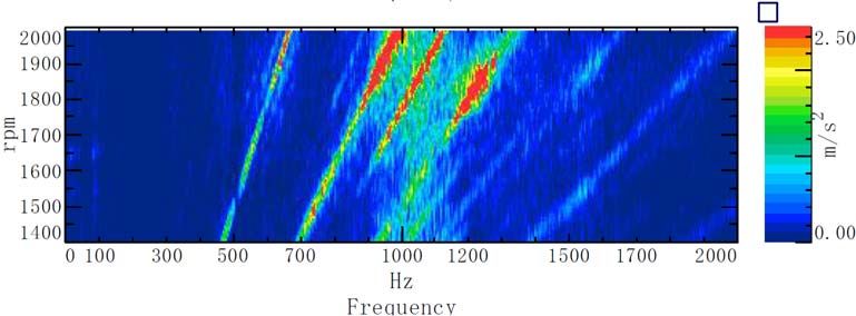
E3S Web of Conferences 260, 03002 (2021)                       https://doi.org/10.1051/e3sconf/202126003002
AEPEE2021

      structure of the motor controller unit have caused great challenges to its reliability and the
      overall safety of electric vehicles.
           At present, when verifying the reliability of the motor controller unit through simulation,
      it is necessary to use the method of multi-physics coupling analysis. In the simulation, it is
      necessary to consider the influence of electric stress, self-heating, environmental
      temperature and humidity conditions, and vibration conditions. This is very difficult to
      establish an accurate model and analyze. In view of this, the comprehensive load test of the
      motor controller unit is an important method in the reliability design and inspection of the
      motor controller unit.

      2 Related test standards and methods
      China's national test standard for electric vehicle motor control is GB/T18488. The current
      version is the 2015 edition: GB/T 18488.1-2015 “Drive motor system for electric vehicles
      Part 1:Test methods” and GB/T 18488.2-2015 “Drive motor system for electric vehicles
      Part 2:Test methods” [3-4].

      2.1 Vibration test
      Vibration test simulates the performance of samples under the influence of external
      vibration in real working conditions, which is a crucial test method in the reliability
      research of auto parts.
          For the motor controller unit, the vibration load mainly comes from the unsteady
      vibration of the road passing through the suspension system and the steady vibration of
      rotating parts such as the motor and transmission. Unsteady vibration is affected by the road
      surface, and the vibration excitation is randomly distributed in the time domain and
      frequency. Therefore, broadband random vibration is used to simulate unsteady vibration in
      the vibration test; The frequency of steady state vibration is related to the motor speed. The
      vibration peak value changes with the speed in the frequency domain to show an obvious
      order relationship, showing regularity. In the vibration test, the sinusoidal frequency sweep
      vibration is used to simulate [5].Applying different vibration loads to the sample can test
      the reliability of the sample in different actual use situations.

      2.1.1 Sinusoidal vibration test
      The 2006 edition of GB/T18488 quoted the Chinese automotive industry standard QC/T
      413-2002 Basic Technical Conditions of Automotive Electrical Equipment for the vibration
      test of motor controller units. Compared with QC/T 413-1999, which was replaced by
      QC/T 413-2002, the "fixed frequency vibration" is deleted in the sinusoidal vibration
      section but the "sweep frequency vibration" content is added. Intensified attention has been
      paid to the influence of order wide-frequency band vibration excitation generated by the
      variable-speed motion of rotating parts in automobiles [6].
          The 2015 edition of GB/T18488 quoted the Chinese national test standard GB/T2423.10
      -2008 “Environmental testing for electric and electronic products Part 2: Tests methods
      Test Fc: Vibration (sinusoidal)” as the sinusoidal vibration test method.
          The severity of the standard test for sinusoidal vibration is controlled by parameters
      such as frequency, vibration acceleration amplitude, frequency sweep speed, and test time.
      The conditions are shown in Table 1.

                                                    2
E3S Web of Conferences 260, 03002 (2021)                              https://doi.org/10.1051/e3sconf/202126003002
AEPEE2021

                                  Table 1. Sinusoidal vibration test conditions.
                                                            Vibration               Frequency
        Installation    Frequency      Vibration                                                    Test
                                                           acceleration            sweep speed
          location         /Hz       amplitude /mm                                                time /h
                                                         amplitude /(m/s2)          /(otc/min)
                          10-50            2.5
          Engine                                                 --                    8             8
                         50-200            0.16

                          10-25            1.2                   --
       Other location                                                                  8             8
                         25-500             --                  30

         In the electric vehicle motor controller unit test, there is no engine in the electric vehicle
     structure, and the test conditions generally quote "other location".

     2.1.2 Random vibration test
     Compared with the previous version of 2006, GB/T18488-2015 adds random vibration
     content and pays more attention to the impact of unsteady excitation. The random vibration
     test method refers to the national standard GB/T 28046.3-2011 “Road vehicles-
     Environmental conditions and testing for electrical and electronic equipment-Part 3:
     Mechanical loads”, according to the installation location, the test conditions related to
     electric vehicle motor controller units are cited among them "Test IV-Passenger car
     elastomer (body)" [7].

     2.2 Environmental test
     The environmental test simulates the reliability of the tested sample under extreme weather
     conditions. GB/T18488-2015 “Drive Motor System for Electric Vehicles” divides the
     environmental test into three parts: low temperature reliability test, high temperature
     reliability test, and damp heat reliability test.
         Winters in northern China are long and extreme cold weather occurs frequently. In order
     to verify the impact on the reliability of electric vehicles under cold weather conditions, the
     low temperature reliability test requires the test at -40°C. In southern China, the summer is
     hot, with persistent high temperatures often occurring. At the same time, some provinces
     along the southeast coast have humid climate and frequent rainfall. The working
     environment of auto parts is often harsher. In order to verify the adverse effects of high
     temperature and high humidity on auto parts, the high temperature reliability test requires
     the ambient temperature to be above 85℃ for testing, and the humid heat test requires 40℃
     relative humidity 90%~95% conditions to verify reliability.

     3 Comprehensive load vibration test conditions

     3.1 Vibration test conditions

     3.1.1 Sinusoidal vibration test conditions
     The function of the sine frequency sweep test is to check the reliability of the sample
     subjected to vibration excitation of a stable frequency. The steady-state frequency vibration
     load received by the motor controller unit mainly comes from the vibration generated by

                                                        3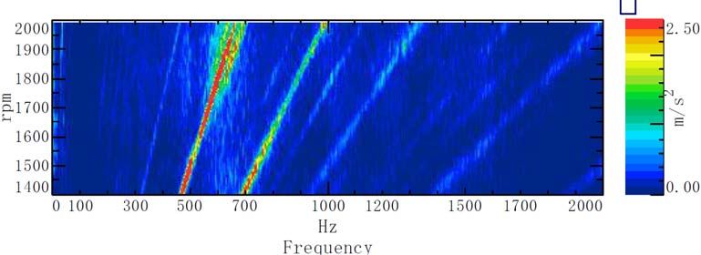
E3S Web of Conferences 260, 03002 (2021)                           https://doi.org/10.1051/e3sconf/202126003002
AEPEE2021

      the motor during rotation, and the vibration generated by the motor is more severe when
      accelerating.
          When a real vehicle accelerates on a flat road, a vibration acceleration sensor is
      arranged on the motor to collect its vibration signal. After the vibration signal is Fourier
      transformed, the relationship between the vibration acceleration in the X, Y, and Z
      directions of the motor and the speed and frequency is shown in Figure 1.

      Fig. 1. Motor vibration diagram under real vehicle acceleration conditions.
          The peak value of motor vibration is below 1500Hz. In the sinusoidal test, the upper
      frequency limit is set to 1500Hz.

      3.1.2 Random vibration test conditions
      The random vibration test method quoted the Chinese national standard GB/T 28046.3-
      2011 “Road vehicles-Environmental conditions and testing for electrical and electronic
      equipment-Part 3: Mechanical loads” “Test IV-Passenger Car Elastomers (Body)”

                                                        4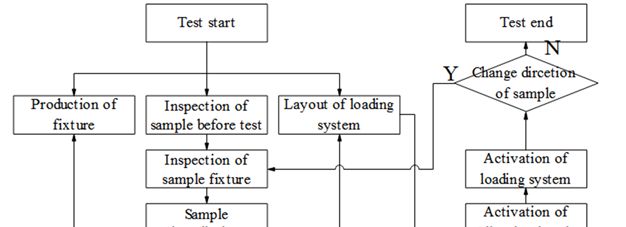
E3S Web of Conferences 260, 03002 (2021)                                             https://doi.org/10.1051/e3sconf/202126003002
AEPEE2021

     Provisions. The standard requires 8 hours of vibration in each direction, the RMS value of
     vibration acceleration is 27.68m/s2, and the relationship between power spectral density and
     frequency is shown in Table 2.
                         Table 2. Power spectral density and frequency relation table.

                                                      Frequency/Hz       PSD(m/s2) 2/Hz
                                                            10                20
                                                            50                6.5
                                                           180                0.25
                                                           300                0.25
                                                           360                0.14
                                                           1000               0.14

     3.2 Environmental test conditions
     The structure of the motor controller unit is complex. The shell is mostly made of metal
     materials such as steel and aluminum. There are copper conductive parts inside, as well as
     many electronic components such as PCB board and many inductors, capacitors, chips and
     so on soldered on the PCB board. Various components have complex structures and
     different materials, and their thermal conductivity, material strength, and thermal expansion
     coefficient are different, showing different thermal stress states.
         In the environmental test, a single high temperature or low temperature reliability test
     can no longer meet the increasingly stringent reliability requirements, so GB/T 28046.4-
     2011 “Road vehicles-Environmental conditions and testing for electrical and electronic
     equipment-Part 4: Climatic loads” 5.3.1 The temperature cycle of the specified rate of
     change is used as the environmental condition of the comprehensive load vibration test. The
     test conditions are shown in Figure 2 [8].
                                            100
                                            80
                          Temperature/(℃)

                                            60
                                            40
                                            20
                                             0
                                            ‐20
                                            ‐40
                                            ‐60
                                                  0   50    100 150 200 250 300 350 400 450
                                                                     Time/(min)

     Fig. 2. Environmental test conditions.
         In the comprehensive load vibration test, due to the harsh environmental test conditions,
     the vibration sensor and its wiring harness must be able to withstand the extreme high and
     low temperatures in the environmental conditions. Otherwise, the feedback signal of the
     vibration test will be inaccurate and the test will fail.

     3.3 Load condition
     In the process of real vehicle driving, due to the complex road conditions, electric vehicles
     often cannot drive at a constant speed at the rated speed, especially in urban road conditions

                                                                     5
E3S Web of Conferences 260, 03002 (2021) https://doi.org/10.1051/e3sconf/202126003002
AEPEE2021
where the road is congested and the car starts and stops frequently. The working conditions
of the motor controller unit are also more complicated, and the electrical stresses on the
internal electronic components are also more complicated. The continuous output of the
rated current for a long time during the test obviously cannot fit the actual load environment,
and it is difficult to meet the test requirements.
In order to simulate the real driving situation, by monitoring the current of the motor
controller unit in the actual vehicle test, the output current data of driving under different
road conditions can be summarized, and a representative vehicle controller output working
condition can be obtained, as shown in the figure 3.
600
RMS of output current/(A)
500
400
300
200
100
0
0 50 100 150 200 250 300 350 400 450
Time/(s)
Fig. 3. Motor controller unit output working condition curve.
4 Comprehensive load vibration test process
4.1 Test subject process
There are strict requirements for the control and test equipment and related parts of the
integrated load vibration test process. The main body is divided into the production of
fixtures, the inspection of sample before test, the layout of the loading system, the
installation of the sample fixture, the layout of the chamber, the connection of the loading
system, the activation of the chamber parameter setting, the setting and starting of the
vibration bench parameter, and the parameter setting of the electrical test equipment.
Change the vibration direction, complete the test, arrange and dismantle the equipment, etc.
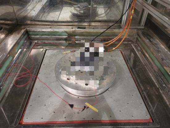
The actual installation diagram of the test sample is shown in Figure 4, and the specific
flowchart is shown in Figure 5.
Fig. 4. Actual installation of test samples.
6
E3S Web of Conferences 260, 03002 (2021)                    https://doi.org/10.1051/e3sconf/202126003002
AEPEE2021

     Fig. 5. Flow chart of test subject.

     4.2 Electrical load test system
         According to the parameters of the motor controller unit, select electrical equipment to
     build a test system to simulate the working environment of the motor controller unit on the
     entire vehicle. The programmable high-voltage DC power supply simulates the battery pack
     on the real car; The inductive load simulates the motor on the vehicle, The low-voltage
     power supply supplies power to the control circuit of the motor controller unit, The chiller
     is connected to the controller for heat dissipation. The test control system with CAN
     communication module uses CAN bus technology to communicate with the motor
     controller unit, simulating VCU sending output current, frequency and other commands to
     the motor controller unit to control the output working condition. The schematic diagram of
     electrical load test systemare shown in Figure 6.

     Fig. 6. Electrical load test system.

                                                  7
E3S Web of Conferences 260, 03002 (2021) https://doi.org/10.1051/e3sconf/202126003002
AEPEE2021
If the test needs to record power supply voltage, chiller flow temperature and other
parameters, also need to use equipment with remote communication capabilities. By
integrating various devices into the test system for common control, the degree of
automation of the test is improved.
5 Three key points in fixture design
The fixture is the link between the vibration test bench and the test sample. The
performance of the fixture will directly affect the test effect of the vibration test. The
following three issues should be paid attention to in the design of fixtures.
5.1 Lightweight
In the vibration test, the fixture as an important auxiliary part of the fixed sample and the
vibration test bench will also participate in the vibration of the test. According to Newton's
second law, the thrust required for vibration test is shown in formula (1).
F m0 m1 m2 m3 a (1)
Among them: F is the thrust required for the test; m0 is the mass of the vibration
bench moving coil; m1 is the quality of the vibration bench table; m2 is the quality of the
fixture; m3 the mass of the vibration test sample; a is the vibration acceleration
In the case of the vibration test bench unchanged, when the moving coil mass and table
quality of the vibration test bench are constant, the greater the quality of the fixtures, the
smaller the sample mass that the vibration test bench can withstand. Therefore, when the
mass of the sample is large or when multiple samples are tested at the same time, the
lightweight design of the fixture should be paid attention to to meet the test
requirements.The lightweight optimization design of a vibration fixture with excessive
mass is carried out, and the design results obtained are shown in Figure 7.
Fig. 7. Fixture before lightweight optimization and optimization results.
5.2 Low damping
IThe fixture plays the role of connecting the sample and the vibration test bench in the test.
If the fixture is regarded as a single degree of freedom vibration system of spring and
damping during the vibration test, the movement of the fixture is shown in formula (2).
F t
mX CX KX (2)
8E3S Web of Conferences 260, 03002 (2021) https://doi.org/10.1051/e3sconf/202126003002
AEPEE2021
Among them: m is the mass; C is the viscous damping coefficient; K is the
stiffness; F t is the external force; X is the displacement; X is the first derivative of
displacement with respect to time; X is the second derivative of displacement with
respect to time.
When the system is excited by a steady-state sinusoid, the amplitude A of the system
vibration is shown in formula (3):
1 Fv
A (3)
K
1 2
2 2 2
Among them: / n ; n2 k / m ; C / 2m n ; Fv / K is the static
displacement under Fv .
It can be seen that the damping coefficient has a very large influence on the
vibration system amplitude. If the damping of the fixture is too large, the transmitted
vibration intensity will be weakened, which will affect the test effect.
5.3 No resonance
Mode is an inherent dynamic characteristic of the structure, and the vibration characteristics
exhibited at different frequencies are called mode shapes. Each modal frequency
corresponds to a unique mode shape. When excited by this modal frequency, the structure
will vibrate violently according to the mode shape, which is called "resonance."
According to the theory of mechanical vibration, for a free vibration system with N
degrees of freedom, the differential equation of the system is shown in equation (4)
M
x C x K x
0 (4)
Among them: M is the mass matrix; K is the stiffness matrix; C is the damping
matrix; x is the acceleration column vector; x is the velocity column vector; x is
the displacement column vector.
For structures with low damping, C is usually ignored. Therefore, the differential
equation of a vibration system that ignores the effect of damping is shown in equation (5).
M
x K x 0 (5)
According to the characteristics of the second-order linear homogeneous differential
equation, assuming xi qi sin it , substituting formula (5) into (6) can be obtained.
M K q
i
2
0 i (6)
If it has a non-zero solution, as shown in equation (7).
i2 M K
0 (7)
9E3S Web of Conferences 260, 03002 (2021) https://doi.org/10.1051/e3sconf/202126003002
AEPEE2021
This equation is called the characteristic equation of the mechanical vibration system,
which is the N-th order equation of i . The N-order characteristic equation of the vibration
2
system corresponds to N different non-zero solutions, that is, the modal frequency of the
system. If the fixture is here When the structure is excited, resonance will appear [9].
In the fixture design stage, modal simulation and optimization should be carried out to
determine that its natural frequency distribution is far away from the vibration test
frequency to save trial costs and ensure test quality.
6 Conclusion
The motor controller unit is affected by the electrical load, mechanical load, and climate
load when it is working, and the working conditions are harsh. However, as a key
component of an electric vehicle, it needs to have good reliability. This article summarizes
the three main loads of motor controllers. These three loads are vibration mechanical load,
temperature cycle climate load and electrical load close to actual working conditions.
According to three kinds of loads, a reliability test method is proposed. Summarize the test
system composition required in the key test process test according to the method. And
deduced the important light weight, low damping, and no resonance principles in the
vibration mechanical load test. A new idea is proposed for the reliability test of the motor
controller.
References
1. Energy-saving and new energy automobile industry development plan [J] China Motor,
2012(08):60-67.
2. ZHAO Y F, YANG W S, LI R J, SONG X M. Analysis on Development Trend of Pure
Electric Vehicles in China[J]. Auto Engineer, 2020(07):14-17.
3. GB/T 18488.1-2015 Drive motor system for electric vehicles Part 1:Test
methods[S].Beijing: Standards Press of China,2015
4. GB/T 18488.2-2015 Drive motor system for electric vehicles Part 2:Test
methods[S].Beijing: Standards Press of China,2015
5. HUANG X, HE P L, CAI Z T. Research on Evaluation Methods of Random Vibration
of EV Drive Motor System[J] . Auto Electric Parts,2018(01):10-13+15.
6. GAO S, GAO Q.Study on Vibration Test Method for Electrical Machine and
controllers of Electric Vehicles[J]. Environmental Technology,2013,31(01):24-28.
7. GB/T 28046.3-2011 Road vehicles-Environmental conditions and testing for electrical
and electronic equipment-Part 3: Mechanical loads [S].Beijing: Standards Press of
China,2011
8. GB/T 28046.4-2011 Road vehicles-Environmental conditions and testing for electrical
and electronic equipment-Part 4:Climatic loads [S].Beijing: Standards Press of
China,2011.
9. SU S J, XU Y L, ZHANG Z Y. Modal analysis of automobile wheels based on
different materials[J]. Automobile Applied Technology,2018(19):225-226+235.
10You can also read