Home Environment Monitoring And Lighting Control Using Cloud Mqtt Dashboard
←
→
Page content transcription
If your browser does not render page correctly, please read the page content below
INTERNATIONAL JOURNAL OF SCIENTIFIC & TECHNOLOGY RESEARCH VOLUME 9, ISSUE 02, FEBRUARY 2020 ISSN 2277-8616
Home Environment Monitoring And Lighting
Control Using Cloud Mqtt Dashboard
Dhiraj Sunehra, Sathish Sandu
Abstract: Home environment monitoring and automation helps to secure the home from accidental hazards and provides convenience to the user. Due
to the recent technological developments in the field of communications, several authors are implementing Internet of Things (IoT) based embedded
systems. In this paper, we implement an embedded system based on IoT consisting two subsystems, one subsystem for monitoring various home
environment parameters such as temperature, humidity, gas leakage, occurrence of any fire accident, and rain, and another subsystem for automatic
lighting control in the home based on the measurement of light intensity. The system is built using Arduino Mega 2560, several sensors and NodeMCU
as a Wi-Fi module. The necessary software is developed in Embedded C using the Arduino Integrated Development Environment (IDE). The sensor data
is fed to the Arduino which checks the set threshold conditions, and then uploads the information about each environment parameter on to the Cloud
Message Queue Telemetry Transport (MQTT) webserver as well as MQTT dashboard android application. PIR sensor detects any motion in the room
and turns on the light in the presence of a living being inside the room. This helps saving the energy consumption. The SSR dimmer circuit and light
dependent resistor (LDR) are used to control the light intensity of the bulb based on the lighting in the room.
Index Terms: Arduino Mega 2560, Automatic lighting control, Cloud MQTT Dashboard android app, Light Dependent Resistor, NodeMCU, PIR Sensor,
Secure Home Environment.
—————————— ——————————
1 INTRODUCTION Ravi Kishore and Aditya Valdas implemented an
In today‟s world, automation has become important and is environmental monitoring system for safety of the employees,
being used in many applications in our daily life. A Home with the help of Losant MQTT based IoT platform, in which
Automation System (HAS) is a system where in home they monitor the gas leakage and flame occurrence continually
appliances or environment is controlled without much human [3]. Ying-Wen Bai and Yi-Te Ku implemented an automatic light
involvement. It saves power, time and efforts and is more intensity control system based on the lighting present in the
efficient than the conventional systems. Home environmental room, with the help of Home light control module (HLCM) in
monitoring is a major Internet of Things (IoT) application, which they used Passive Infrared Sensor (PIR) sensor for
which involves monitoring the inside and outside environment motion detection. RF module is used for transmitting and
of the home. By using IoT technology, user can create receiving data to each HLCM to control the light intensity [4].
advanced Home Automations Systems that can improve the Wahab implemented a home automation system which is
quality of the life. The objective of this paper is to develop a based on IoT to control the electrical appliances such as the
home environmental monitoring system to measure different bulb and fan at home easily and efficiently via Wi-Fi for the
parameters like temperature, humidity, occurrence of fire, personally disabled persons. The sensors monitor the motion,
occurrence of rain and presence of any hazardous gases. humidity and temperature of the house [5].
Monitoring of these parameters is not only helpful in homes,
but also in industry and for weather forecasting. Another 3 HARDWARE DESCRIPTION
objective of this paper to provide a well organized and energy
saving lighting system based on the lighting intensity in the 3.1 Block diagram of the system
room. The system adjusts the light brightness according to the Figure 1 shows the block diagram of home environment
presence of human being and light intensity in the room. monitoring and automatic lighting control system. The system
consists of a central Arduino Mega 2560 board which
2 LITERATURE REVIEW interfaced with various sensors such as Temperature and
Khalil Ullah and M. Asadullah implemented a Bluetooth humidity sensor (DHT11), Passive Infrared Sensor (PIR), IR
technology based home monitoring and controlling system flame sensor, MQ2 gas sensor, Rain sensor, LDR sensor and
which monitors the home environmental parameters such as SSR dimmer circuit. The outputs from the sensors are sent by
soil moisture, temperature and humidity, and controls the Arduino to the ESP8266 NodeMCU Wi-Fi module, which
appliances within the short range of 20 m using Bluetooth transmits the sensed data to the CloudMQTT webserver and
technology [1]. Zafar and Miraj implemented a real time MQTT dashboard android application.
temperature and humidity monitoring system with the help of
Arduino in which they monitor only the temperature and
humidity values and upload that data to ThingsSpeak
webserver [2].
_____________________________
• Dr. Dhiraj Sunehra is currently working as a Professor of Electronics &
Communication Engineering in Jawaharlal Nehru Technological
University Hyderabad, India, PH-+91-7893278314. E-mail:
dhirajsunehra@yahoo.co.in Fig. 1. Block diagram of the home environment monitoring and
• Mr. Sathish Sandu is currently pursuing masters degree program in automatic lighting control system
Digital Systems & Computer Electronics in Jawaharlal Nehru
Technological University Hyderabad, India, PH-+91-9866368748. E-
mail: sathishsandu786@gmail.com 3539
IJSTR©2020
www.ijstr.org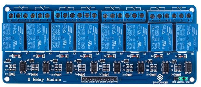
INTERNATIONAL JOURNAL OF SCIENTIFIC & TECHNOLOGY RESEARCH VOLUME 9, ISSUE 02, FEBRUARY 2020 ISSN 2277-8616
from the digital output pin (Fig. 4). DHT11 is having resistive
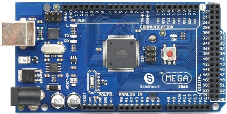
3.2 Arduino Mega 2560 type of humidity measurement component. For measurement
All Arduino boards use the Atmel Corporation‟s AVR family of temperature, it is having a Negative temperature coefficient
processors for their boards. The microcontrollers use modified (NTC) type component. It can measure humidity within the
Harvard architecture with single chip of a 8 or 16-bit Reduced range of 20% to 90% with an accuracy of ±5%, and
Instruction Set Computers (RISC) architecture [6]. The Arduino temperature up to 100°C with an accuracy of ±1°C [8].
Mega uses an AVR ATmega 2560 microcontroller. The board
has 54 digital I/O pins (out of which 15 can be used as PWM
outputs), 16 MHz crystal, USB connection, 4 serial hardware
ports (UART), a power connector, ICSP programming
connector and a reset button (Fig. 2). ATmega 2560 comes
with 256KB non-volatile reprogrammable flash memory to
store the program, 8KB volatile static RAM used to write or
read data during program execution, 4KB byte addressable
nonvolatile EEPROM to permanently store variables and recall
them during program execution.
Fig. 4. DHT11 Sensor
3.5 Rain Sensor
Rain sensor is used to detect the raindrops (Fig. 5). If any rain
drops fall on the rain detecting plate, then the plate gets short
circuited and the output is high. If no water drops falls on the
rain detecting plate, then its output is low. This module has a
power indicator LED, which turns on, in the event of rain
detection; otherwise it is in off state. The rain sensor sensitivity
can be adjusted using the potentiometer provided on the
sensor [9].
Fig. 2. Arduino Mega 2560 Board
3.3 PIR Sensor
Passive Infrared (PIR) sensor is used to detect the motion of
nearby human beings in its measuring range (Fig. 3). It works
on high-low logic. If any motion is detected, its output is high
(3.3V) and when there is no motion detected, its output is low
(0V). PIR sensor accepts input voltage in the range of 4.5V to
12V, but 5V is recommended. It can measuring range is up to
7 m and operating temperature range is -20° to +80° Celsius
[7].
Fig. 5. Rain sensor
VCC pin of rain sensor is connected to the VCC pin of the
Arduino Mega 2560 board, GND is connected to the GND pin
of the arduino board. Either the digital pin or analog pin is used
as output pin depending on the requirement. Here we use the
analog pin as the output pin, and it is connected to the analog
pin A2 of the arduino board.
3.6 Gas Sensor
MQ-2 Gas sensor is used for detection of the hazardous
gases like Methane, Butane, LPG and Smoke (Fig. 6). MQ2
gas sensor is also called as Chemi-resistor. It has a sensing
Fig. 3. PIR Sensor substance whose resistance changes, when it comes in
contact with any harmful gases. Concentration of gas is
GND pin of PIR sensor is connected to the GND pin of the measured using a voltage divider network. By using this
Arduino Mega 2560 board, Dout (digital output) pin is sensor, we can measure gas concentration in the range of 200
connected to the digital PWM pin 08 of the Arduino board, and to 10000ppm with an operating voltage of 3.3V to 5V [10].
VCC pin is connected to the VCC pin of the arduino board.
3.4 DHT11 Sensor
DHT11 sensor used as a weather sensor to read the
temperature and humidity in the environment from time to time
3540
IJSTR©2020
www.ijstr.org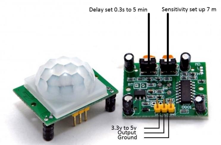
INTERNATIONAL JOURNAL OF SCIENTIFIC & TECHNOLOGY RESEARCH VOLUME 9, ISSUE 02, FEBRUARY 2020                        ISSN 2277-8616

                                                                     circuit, brightness of the bulb is controlled by a SSR Dimmer
                                                                     circuit. The SSR dimmer circuit is built using a Triac [13].

                     Fig. 6. MQ-2 Gas Sensor                                         Fig. 8. Light Dependent Resistor

VCC pin of the gas sensor is connected to the VCC pin of the         3.9 Relay Module
Arduino Mega 2560 board, GND is connected to the GND pin             Relay is an electro-mechanical module is used to turn ON/OFF
of the arduino board. Either the digital pin or analog pin can be    a device by sending a small signal at the output. Fig.9 shows a
used as output pin depending on the requirement. In this work        8- channel relay with 8-relays on a single PCB, but only 4
analog pin is used as output pin and it is connected to the          relays are used here. The input to the relays IN1, IN2, IN3,
analog pin A1 of the arduino board.                                  and IN4 are connected to the Arduino‟s 12, 11, 10 and 9 pins
                                                                     respectively, to turn ON the corresponding relay. The output
3.7 IR Flame Sensor                                                  pins of each relay consist of a common terminal (COM),
IR Flame sensor is used to detect if there is any flame source       normally open (NO) and normally closed (NC) [14].
in the wavelength range of 760nm to 1100nm. It will give both
analog and digital outputs when output is connected to the
respected pins if output pin is connected to digital pin then it
going to give High logic for flame detection and Low logic for
no flame detected state and if output is connected to analog
pin then it going to give values in the range of 0 to 1024 here if
the values increased from 0 to 1024 drastically then there is
warning of flame detection exist then led going to up in the
sensor [11]. IR Flame sensor is shown in Fig. 7.

                                                                                          Fig. 9. 8-Channel Relay
                                                                     3.10 NodeMCU
                                                                     NodeMCU stands for Node Micro Controller Unit, an open
                                                                     source platform based on IoT that is used to connect the
                                                                     devices to the internet. NodeMCU is based on the firmware
                                                                     ESP8266, a low cost chip with inbuilt Wi-Fi module to connect
                                                                     to the Internet [15]. Here NodeMCU is used to the upload
                                                                     sensor data on to the MQTT webserver (Fig. 10).

                    Fig. 7. IR Flame sensor

VCC pin of IR flame sensor is connected to the VCC pin of the
Arduino mega 2560 board, GND pin is connected to the GND
pin of the Arduino board and Either digital pin or analog pin is
used as output pin depending on our requirement but in this
system analog pin as output pin so it is connected to the
analog pin A3 of the Arduino board.

3.8 LDR Sensor to control SSR Dimmer circuit
LDR uses a semiconductor material for detecting the ambient
light intensity (Fig. 8). When light falls on the LDR, its
resistance decreases [12]. LDR is interfaced to the Arduino                             Fig. 10. NodeMCU Module
Mega 2560 to measure the intensity level of the light present
in the room. Based on the intensity level measured by the LDR
                                                                                                                               3541
                                                             IJSTR©2020
                                                             www.ijstr.org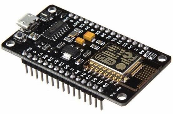
INTERNATIONAL JOURNAL OF SCIENTIFIC & TECHNOLOGY RESEARCH VOLUME 9, ISSUE 02, FEBRUARY 2020 ISSN 2277-8616
4 SOFTWARE TOOLS
4.1 Arduino Integrated Development Environment
The Arduino IDE contains a text editor for writing the code. In
Arduino IDE, we write the program in Embedded C. These
programs called sketches are saved with .ino file extension.
Later the program debugged and uploaded on to the Arduino
board. Arduino IDE runs on MAC OS X, Linux, and Windows
and it is an open source software [6].
4.2 Embedded C Language
Embedded C Language is the soul of the processor and it will
be used in each and every embedded system projects. Each
processor is associated with an embedded software.
Embedded C language is mainly used to program the
microcontroller.
4.3 Cloud MQTT Web server
MQTT protocol is a lightweight publish and subscribe system,
where you can publish and receive messages as a client. With
this protocol, multiple devices like constrained devices with
low bandwidth can be communicated, thus it is called simple
messaging protocol. This protocol widely used in IoT
applications. MQTT allows to send a command to control an
output or can read from a sensor and publish it [16].
4.4 MQTT Dashboard Android Application
There are many open source applications available to
subscribe or publish for MQTT clients. We are using MQTT Fig. 12. Flowchart of the sequence of events that take place in
Dashboard android application for displaying the sensors data, the home environment and automatic lighting control system
obtained from the Cloud MQTT.
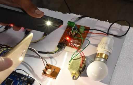
5.3 Experimental Setup
Figure 13 shows the experimental setup of Wi-Fi based Home
5 RESULTS AND DISCUSSION environment monitoring and automatic lighting control system.
The PIR sensor, rain sensor, temperature and humidity
5.1 Schematic Diagram (DHT11) sensor, IR flame sensor, Gas sensor (MQ2), SSR
The schematic diagram of the Home Environment Monitoring Dimmer, LDR, Node MCU module and relays are interfaced to
and Automatic Lighting Control System using Arduino Mega the Arduino Mega2560 board. Two fans, Two lights and a
2560 and Cloud MQTT Server is shown in Fig. 11. sprinkler are connected using a eight channel relay. The relays
are switched on/off depending upon sensor data threshold
values. The Arduino board requires a DC voltage of 7-12 V or
it can be operated using the USB port of a laptop which
provides 5V. The transmit pin of Arduino is connected to the
receive pin of NodeMCU.
Fig.11. Schematic Diagram
Here analog voltage pin of dimmer is connected to analog pin
A4, zero cross detector pin is connected to digital pin 02,
control pin is connected to digital pin 07, and relay inputs IN1,
IN2, IN3 and IN4 are connected to pins 12, 11, 10 and 9 pins
of the arduino respectively to control the Light, Sprinkler, Fan
and Exhaust Fan. The interfacing of other modules with the
Arduino is discussed earlier.
Fig. 13. Experimental Setup
5.2 Flowchart
3542
IJSTR©2020
www.ijstr.org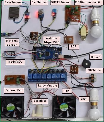
INTERNATIONAL JOURNAL OF SCIENTIFIC & TECHNOLOGY RESEARCH VOLUME 9, ISSUE 02, FEBRUARY 2020 ISSN 2277-8616
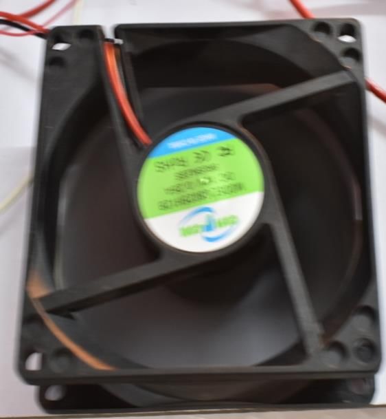
5.4 Experimental Results The Gas sensor is used to detect the presence of any harmful
Various experiments are conducted to validate the working of gases such as LPG, methane, carbon monoxide, etc. in the
various sensors used in the home environment monitoring and room (Fig. 18). If any harmful gas is found in the room, then
automatic lighting control system. A hand is placed before the the exhaust fan turns on using relay 4 (Fig. 19). Also a buzzer
PIR sensor to detect any motion in the room. When the motion alert is provided to alert the persons staying in the home.
is detected, it indicates the presence of a living being inside
the room and the HAS will turn on the light in the room through
the relay 1 as shown in Fig. 14.
Fig. 14. Setup showing PIR sensor used for detection of a
living being
Figure 15 shows the PIR sensor status in the Cloud MQTT
Dashboard android application as “Motion Detected” and the Fig. 17. Cloud MQTT Dashboard Output showing Rain Status
Light status is shown as ON. Temperature and Humidity as „YES‟
sensor (DHT 11) is used to measure the temperature and
humidity in the room. The measured temperature and humidity
values at an epoch are 77% and 29C respectively. If DHT11
sensor temperature value is less than the threshold, i.e. 28C,
then the Fan is in OFF state, and if temperature is greater than
the threshold value, then the Fan will be in ON state (Fig. 15).
Fig. 18. Setup for checking Gas Leakage using MQ2 sensor
Fig. 15. Cloud MQTT Dashboard showing Motion Detected,
ON status of the Light, Temperature and Humidity information
Figure 16 shows the rain sensor with water drops placed on
the rain detecting plate. Figure 17 shows the rain status as
„YES‟ on the Cloud MQTT dashboard.
Fig. 19. Exhaust Fan ON in case of a Gas leakage
Figure 20 shows the corresponding gas leakage as “YES” and
exhaust fan status as “ON” on the MQTT dashboard.
Fig. 16. Rain sensor used for detecting the rain (water drops)
3543
IJSTR©2020
www.ijstr.org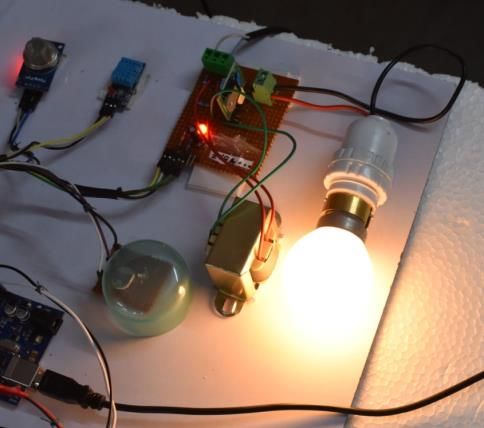
INTERNATIONAL JOURNAL OF SCIENTIFIC & TECHNOLOGY RESEARCH VOLUME 9, ISSUE 02, FEBRUARY 2020                       ISSN 2277-8616

                                                                   The SSR dimmer circuit controls the brightness of the light in
                                                                   four cases depending on the light intensity in the room with the
                                                                   help of LDR circuit. In the case 1, light intensity with high
                                                                   brightness level is detected by the LDR in the room, then bulb
                                                                   is turned off (Fig. 23).

  Fig. 20. Gas Leakage status and Exhaust fan ON status in
                     MQTT dashboard

The IR flame sensor detects the occurrence of any flame in          Fig. 22. Flame detected, Buzzer Status and Sprinkler Status
the home (Fig. 21). When a flame is detected, water sprinkler                       shown in MQTT Dashboard
is turned on through relay 2 and a buzzer alert is provided to
the persons staying in the home. A lighter is used here to test
for occurrence of flame.

                                                                      Fig. 23. Case 1: High Room brightness then Light is OFF.
      Fig. 21. Setup for Flame Detection using a lighter
                                                                   In the case 2, natural lighting in the room is at medium level,
                                                                   so the LDR detects this light intensity, and then the bulb glows
                                                                   with normal brightness as shown in the Fig. 24.

Figure 22 shows the snapshot of Cloud MQTT dashboard with            Fig. 24. Case 2: Medium Room Brightness then Bulb glows
    flame detected status as “YES”, flame buzzer alert as                              with Normal Brightness
           “Warning” and Sprinkler status as “ON”.
                                                                   In the case 3, low light intensity is detected by LDR in the
                                                                                                                              3544
                                                           IJSTR©2020
                                                           www.ijstr.org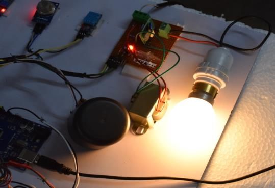
INTERNATIONAL JOURNAL OF SCIENTIFIC & TECHNOLOGY RESEARCH VOLUME 9, ISSUE 02, FEBRUARY 2020                               ISSN 2277-8616

room (semi transparent lid is placed over the LDR), then the                      Computing and Communication Technology (ICATCCT),
bulb glows with higher brightness as shown in Fig. 25.                            21-23 Dec. 2017, Tumkur, India, pp. 152-155.
                                                                             [4] Ying-Wen Bai and YI-Te Ku, “Automatic room Light intensity
                                                                                  Detection and Control using a Microprocessor and Light
                                                                                  sensors”, IEEE International Symposium on Consumer
                                                                                  Electronics, 07 August 2008, Vilamoura, Portugal, pp.1-4.
                                                                             [5] M.H.A. Wahab, “IoT based home automation system for
                                                                                  people with disabilities,” 5th International Conference on
                                                                                  Reliability, Infocom Technologies and Optimization (Trends
                                                                                  and Future Directions) (ICRITO), 7- 9 September 2016,
                                                                                  Noida, India, pp. 51-51.
                                                                             [6] Website 1: https://www.arduino.cc › Reference › Data
                                                                                  Sheets
                                                                             [7] Data sheet of Passive Infrared (PIR) sensor:
                                                                             [8] (https://www.mpja.com/download/31227sc.pdf.)
Fig. 25. Case 3: Room with low brightness (semi transparent                  [9] Data sheet of DHT11 Temperature and Humidity sensor:
lid placed over LDR) then Light glows with higher brightness                 [10] (http://robocraft.ru/files/datasheet/DHT11.pdf)
                                                                             [11] Data sheet of Rain sensor:
In the case 4, the room is completely dark, with no light                    [12] (https://www.openhacks.com/uploadsproductos/rain_senso
detected by the LDR (opaque object (lid) placed over the                          r_module.pdf)
LDR), then bulb glows with maximum brightness level as                       [13] Data sheet of MQ2 gas sensor:
shown in Fig. 26.                                                            [14] (https://www.olimex.com/Products/Components/Sensors/S
                                                                                  NSMQ2/resources/
                                                                             [15] MQ2.pdf)
                                                                             [16] Data sheet of Flame sensor:
                                                                             [17] (https://4.imimg.com/data4/AV/UT/MY-23669504/flame-
                                                                                  sensor-module-arduino.pdf)
                                                                             [18] Data sheet of Light Dependent Resistor(LDR) sensor:
                                                                             [19] (https://components101.com/ldr-datasheet)
                                                                             [20] Data sheet of SSR dimmer circuit :
                                                                             [21] (https://www.instructables.com/id/Arduino-controlled-light-
                                                                                  dimmer-The circuit/)
                                                                             [22] Data sheet of Relay module:
                                                                             [23] (https://components101.com/5v-relay-pinout-working-
                                                                                  datasheet)
                                                                             [24] Data sheet of ESP 8266 NodeMCU Wi-Fi module:
 Fig. 26. Case 4: Room fully dark (Opaque object (lid) placed                [25] (https://www.elecrow.com/download/ESP-12F.pdf)
    over LDR) then Light glows with Maximum Brightness                       [26] Website 2: https://www.cloudmqtt.com/docs/index.html.

6 CONCLUSIONS
A Home environment monitoring and automatic lighting control
system is implemented to secure the home and turn on the
lights in the presence of living beings in the room. The
environment parameters and other sensor data can be
monitored on the Cloud MQTT webserver as well as MQTT
dashboard App. The Cloud MQTT webserver / MQTT
dashboard can be accessed remotely using an internet
enabled device such as smart phone or laptop.

7 REFERENCES
    [1] M. Asadullah and K. Ullah, “Smart Home Automation
        System using Bluetooth technology”, “International
        Conference on Innovations in Electrical Engineering and
        Computational Technologies(ICIEECT), 5-7 April 2017,
        Karachi, Pakistan , pp.1-6.
    [2] Zafar and Miraj, “An IoT Based Real-Time Environmental
        Monitoring System Using Arduino and Cloud Service”,
        International Journal of Engineering, Technology & Applied
        Science Research, Vol. 8, No. 4, 2018, pp. 3238-3242.
    [3] R. K. Kodali and A. Valdas, “MQTT based environment
        monitoring in factories for employee safety”, 3rd
        International Conference on Applied and Theoretical

                                                                                                                                        3545
                                                             IJSTR©2020
                                                             www.ijstr.org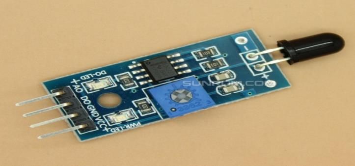
You can also read