FINITE ELEMENT ANALYSIS OF TWO-WAY HOLLOW HIGH STRENGTH SELF-COMPACTING FIBER REINFORCED CONCRETE SLAB UNDER THE EFFECTS OF UNIFORM REPEATED LOAD ...
←
→
Page content transcription
If your browser does not render page correctly, please read the page content below
Journal of Engineering Science and Technology
Vol. 16, No. 1 (2021) 750 - 761
© School of Engineering, Taylor’s University

 FINITE ELEMENT ANALYSIS OF TWO-WAY HOLLOW HIGH
 STRENGTH SELF-COMPACTING FIBER REINFORCED
 CONCRETE SLAB UNDER THE EFFECTS OF UNIFORM
 REPEATED LOAD (USING TWO-WAY PIPING SYSTEM)

 WALEED A. TAMEEMI1,*, NAMEER A. ALWASH2
 1College of Engineering, University of Babylon, 60th St., 51001, Al-Hilla, Babylon, Iraq
2College of Engineering, University of Babylon, Al-Gamaia St., 51001, Al-Hilla, Babylon, Iraq
 *Corresponding Author: eng.waleed.ali@uobabylon.edu.iq

 Abstract
 This paper offers detailed data regarding the mechanical behaviour of two-way
 hollow high strength self-compacted fiber reinforced concrete slabs that were
 tested under the influences of uniform repeated loads. In this research, a
 comparison between the results of the numerical analysis and the experimental
 results of previous research is presented to confirm the suitability of the
 convergence study, material properties, elements types, and the real constants of
 the proposed model of two-way hollow slabs using an innovative two-way piping
 system. This new type of voiding system could be fabricated through placing
 continuous two-way plastic piping system, inside the reinforced concrete slabs to
 reduce the self-weight of the produced slabs along with offering continues
 networks of voids that could be beneficial for passing service lines, including
 lines for communication, sewage, electricity, and water. The outcomes of this
 research proved that using the nonlinear finite element method showed
 acceptable precision with a maximum difference percentage of about 15% of the
 ultimate capacity between the proposed numerical model and the experimental
 results. Besides, it was shown that it is useful to produced two-way hollow slabs
 using the two-way piping system with keeping about 80% of the ultimate
 capacity. Finally, the results showed that the reduction in the strength of the two-
 way hollow reinforced concrete slabs could be reduced using high strength
 concrete, adding micro steel fiber, increasing the reinforcement ratio or by
 locating the piping systems far from the locations of maximum stresses.
 Keywords: FEA, Two-way hollow, Two-way piping system, Uniform repeated
 load.

 750
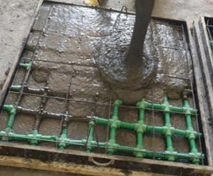
Finite Element Analysis of Two-Way Hollow High Strength Self-Compacting . . . . 751

1. Introduction
Nowadays, it is required to produce multi-story buildings with a huge continuous
distance between columns. This requirement could lead to several disadvantage
points, including higher thickness, higher self-weight, more deflection and more
expensive. Several options are available in practice, including increasing the slab
depth, using prestressing or using hollow slab systems.
 Increasing the depth of reinforced concrete slabs could help by increasing the
stiffness, which could be useful in fulfils the serviceability requirements. However,
using reinforced concrete slab with a higher thickness could also lead to several
disadvantages, such as reducing the precious spacing between two adjacent floors
along with increasing the dead loads and that requires using more oversized
columns and foundations.
 The other option of prestressing could be a good option, but it requires
expensive special equipment and expert staffs. Finally, using hollow reinforced
concrete slab systems could be an advance choice to avoid the previously
mentioned issues [1, 2]. A hollow concrete slab could be constructed by inserting
plastic moulds, styro-foam or polystyrene blocks into reinforced concrete slabs.
 Engineers have been engaging in studying the mechanical behaviour of hollow
slab. It was stated that producing precast hollow-core units by introducing
styrofoam into reinforced concrete slabs showed better structural behaviour than
using PVC pipes [3]. Reduction in the shearing strength, lower maximum loading
capacity, and low ductility previously reported due to increasing the voiding ratio
of hollow core two-way slab [4]. Also, utilizing steel pipes of (32 mm and 42 mm)
in diameter led to enhance the mechanical behaviour by increasing ultimate loading
capacity and cutting down the corresponding deflection [5].
 Inserting cubes and spheres of recycled polypropylene into concrete slab led to
similar or higher ultimate loading capacity than solid slabs and led to lower flexural
stiffness by about 50% [6]. Moreover, increasing the depth of hollow-core
reinforced concrete slab led to decrease the ultimate deflection by 50% and increase
the shear resistance by about 50% while utilizing shear reinforcement in
constructing hollow-slab led to an increase in the shear strength by about 50% and
the maximum deflection by about 50% [7].
 Most researchers have been interested in studying the mechanical performance
of different types of hollow slab systems including hollow-core, BubbleDeck,
Airdeck, U-boot, styro-foam and cobiax. Those systems are used to decrease the
weight of solid slabs by replacing a percentage of the concrete volume by voids,
but no one of those systems could be used for passing service lines.
 On the other hand, the proposed new type of two-way hollow slab system could
also be used to reduce the self-weight along with offering continuous two-way
networks of voids, which could be used for service lines), as shown in Fig. 1.
 This research contains detailed data regarding the finite element analysis (FEA)
by ABAQUS/Standard 2017 of the new type of two-way hollow slab system.

Journal of Engineering Science and Technology February 2021, Vol. 16(1)
752 W. A. Tameemi and N. A. Alwash

 Fig. 1. Constructing two-way hollow reinforced concrete
 slabs using two-way piping systems of plastic pipes and fittings.

2. Details of the testing platform
2.1. Testing parameters
Eleven reinforced concrete slabs (two solid slabs and the rest were two-way hollow
slabs) of (800 × 800 mm) length of effective spans, (880 × 880 mm) overall length
(80 mm) overall thickness were tested under the effects of equivalent uniformly
distributed loads (EUDRL), as shown in Fig. 2. Different variables were considered
in this research producing six parametric studies counting the following:
 • Producing two-way hollow reinforced concrete slabs using two-way piping
 systems with various voiding ratio (0%, 16% and 24%) with a fixed number
 of pipe and fixed distance between pipes (140 mm c/c) was evaluated by
 C65.F0.H16.D32.R1.Au.Lu, C65.F0.H0.D0.R1.A0.Lu and C65.F0.H24.D40.R1.Au.Lu
 concrete slabs.
 • Fabricating two-way hollow reinforced concrete slabs using two-way piping systems
 of different diameters (20 mm, 32 mm and 40 mm) with a fixed (8%) voiding ratio
 was inspected through C65.F0.H8.D40.R1.Au.Lu, C65.F0.H8.D32.R1.Au.Lu,
 C65.F0.H8.D20.R1.Au.Lu, and C65.F0.H0.D0.R1.A0.Lu concrete slabs.
 • Fabricating two-way hollow fiber reinforced concrete slabs using two-way piping
 systems and (1.5%) volume fraction of micro steel fiber of (aspect ratio 75 and
 tensile strength 2600 MPa) was examined through C65.F1.5.H16.D32.R1.Au.Lu,
 C65.F0.H16.D32.R1.Au.Lu, and C65.F0.H0.D0.R1.A0.Lu concrete slabs.
 • Constructing two-way hollow reinforced concrete slabs using two-way piping
 systems with various types of concrete (standard strength concrete with f'c =
 35 MPa and high strength concrete with f'c = 65 MPa) was examined through
 C35.F0.H24.D40.R1.Au.Lu, C65.F0.H24.D40.R1.Au.Lu, C35.F0.H0.D0.R1.A0.Lu and
 C65.F0.H0.D0.R1.A0.Lu concrete slabs.
 • Creating two-way hollow reinforced concrete slabs using two-way piping
 systems with a higher ratio of the primary reinforcement ( =0.004710) for
 bottom layer instead of ( = 0.002355) was evaluated through
 C65.F0.H16.D32.R2.Au.Lu, C65.F0.H16.D32.R1.Au.Lu and C65.F0.H0.D0.R1.A0.Lu
 concrete slabs.
 • Assembling two-way hollow reinforced concrete slabs using different
 configurations of two-way piping systems was evaluated through
 C65.F0.H16.D32.R1.Anu.Lu, C65.F0.H16.D32.R1.Au.Lu and C65.F0.H0.D0.R1.A0.Lu
 concrete slabs.

Journal of Engineering Science and Technology February 2021, Vol. 16(1)
Finite Element Analysis of Two-Way Hollow High Strength Self-Compacting . . . . 753

 C65.F1.5.H16.D32.R1.Au.Lu,
 C35.F0.H0.D0.R1.A0.Lu and
 C65.F0.H16.D32.R1.Au.Lu and
 C65.F0.H0.D0.R1.A0.Lu
 C65.F0.H16.D32.R2.Au.Lu

 C35.F0.H24.D40.R1.A0.Lu and
 C65.F0.H24.D40 C65.F0.H8.D40.R1.A1.L1

 C65.F0.H8.D40.R1.A1.L1
 .R1.Au.Lu

 C65.F0.H16.D32.R1.Anu.Lu
 C65.F0.H8.D20.R1.Au.Lu

 C65.F0.H8.D32.R1.Au.Lu
 Fig. 2. Cross-section details for concrete slabs.

Journal of Engineering Science and Technology February 2021, Vol. 16(1)
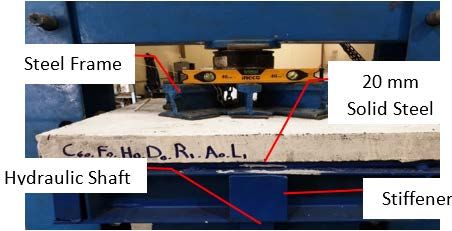
754 W. A. Tameemi and N. A. Alwash

2.2. Materials
Ordinary Portland cement that was satisfies IQS No.5 [8] specifications, fine aggregates
with sieve analysis and properties that agreed with ASTM C136 / C136M – 14 and
IQS No.45 standard tests [9, 10], coarse aggregates with structural properties and
grading that were met the requirements of IQS No.45 standard tests [10], microsilica
that conformed to the requirements of ASTM C1240 – 15 standard specifications [11]
and high range water reducing admixture that agreed with ASTM C494 / C494M – 17
standard test [12] were used in producing self-compacting high strength concrete while
limestone powder was used in making normal strength self-compacting concrete
mixtures. Moreover, micro steel fibers of aspect ratio 75 and tensile strength 2600 MPa,
which were manufactured by Jingjiang Hongtu Engineering Co., were used in
producing fiber reinforced concrete. Steel rebar that satisfies ASTM A1064 / A1064M
- 18a standard test [13] of (4 mm and 6 mm) diameters were used as (secondary and
main reinforcement, respectively) in constructing both the top and bottom layers,
respectively. Finally, plastic fittings and plastic pipes were utilized in assembling two-
way piping systems, as shown in Fig. 1.

2.3. Details of reinforcement
Concrete slabs were reinforced utilizing a layer of six rebar (6 mm in diameter) in
two orthogonal directions at the bottom fiber and a layer of six rebar (4 mm in
diameter) in two orthogonal directions at the top fiber with a uniform spacing of
150 cm c/c except for two-way hollow concrete slab model C65.F0.H16.D32.R2.Au.Lu
of 16% of voids was reinforced utilizing a layer of 12 deformed rebar of 6 mm in
diameter in two orthogonal directions at the bottom fiber with uniform spacing of
75 c cm c/c. A cover of 1 cm was adopted for all concrete slabs.

2.4. Loading and supporting conditions
A rigid I-section steel frame with four solid circular steel shafts (20 mm in
diameter) was used as a supporting system to offer simply supporting condition, as
presented in Fig. 3(a). The equivalent uniformly distributed repeated load was
applied on the reinforced concrete slabs by dividing the applied load of the
universal testing machine into eight regions of (100 mm × 100 mm) through
utilizing I-section steel frame and eight rubber plates of dimensions (100×100×10
mm), as demonstrated in Fig. 3(b). The load was applied through five stages (from
zero to the ultimate level) with a cycle of ten times, except for the last phase was
up to failure, as illustrated in Table 1.

 Table 1. The protocol the equivalent uniformly distributed repeated load.
 *Start
 from *Increased to *Return to Increment Size Number of
Stage ID
 (%) (%) (%) (kN) Cycles
S1 0 20 0 25 10
S2 0 40 0 25 10
S3 0 60 0 25 10
S4 0 80 0 25 10
S5 0 100 End of Test 25 1
*
 as a percentage of the expected ultimate capacity

Journal of Engineering Science and Technology February 2021, Vol. 16(1)
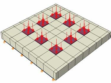
Finite Element Analysis of Two-Way Hollow High Strength Self-Compacting . . . . 755

 (a) (b)
 Fig. 3. Details of loading and supporting parameters.

3. Modelling of Two-Way Hollow RC Slab
ABAQUS/Standard 2017, which is a three-dimensional FE computer program, was
adopted to perform a nonlinear FEA to determine the performance of two-way
hollow reinforced concrete slabs under the effects of EUDRL.

3.1. Convergence study
A convergence study was performed to develop a suitable mesh size throughout
assessing the influences of reducing the element size from (100 mm) to (15 mm),
as shown in Fig. 4(a). As demonstrated in Fig. 4(a), negligible effects were
developed on the load-carrying capacity by decreasing the size of the mesh from
30 to 15 mm. Therefore, a mesh size of 20 mm was selected in this study, as
presented in Fig. 4(b).

 (a) (b)
 Fig. 4. Details of the convergence study.

3.2. Parts and assembly
Five parts, including rebar for main and secondary reinforcement, concrete slab,
solid steel shaft for supports and bearing plates for loading conditions were
involved in modelling two-way hollow reinforced concrete slabs. Solid brick
elements that are Linear Hexahedral elements (C3D8R) of 8-node linear brick were

Journal of Engineering Science and Technology February 2021, Vol. 16(1)

756 W. A. Tameemi and N. A. Alwash

used in meshing steel plates, hollow reinforced concrete slabs and solid reinforced
concrete slabs. Moreover, 3-D linear (T3D2) truss that is 2-node was utilized for
meshing steel rebar.

3.3. Interaction
Different categories of constraints were used to enable the parts to interact with each
other to construct a successive composite system based on experimental observations.
An embedded constrain region was selected to represent the interaction between the
reinforcing rebar and the surrounding model of concrete while a tie constraint was
adopted between the concrete slab and the bearing steel plate along with the concrete
slab and the supporting solid steel shafts, as shown in Fig. 5.

 Embedded Region Tie Constraint Tie Constraint

 Fig. 5. Details of the constraint types.

3.4. Boundary Conditions
Displacement constrained were assigned at the lower surface of the solid steel
shafts in both y-direction and z-direction through the edges of x-axis along with
displacement were constrained in both y-direction and x-direction along the edges
of z-axis to represent the simple supporting condition, as presented in Fig. 6(a).
EUDRL was applied similarly as in the experimental program by applying uniform
pressure on the bearing plates (as shown in Fig. 6(b)) using tabular type amplitudes
to define the protocol of the EUDRL.

 (a) (b)

 Fig. 6. Details of the boundary conditions.

Journal of Engineering Science and Technology February 2021, Vol. 16(1)
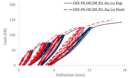
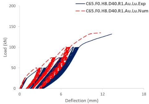
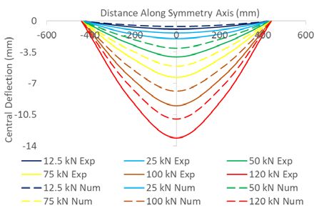
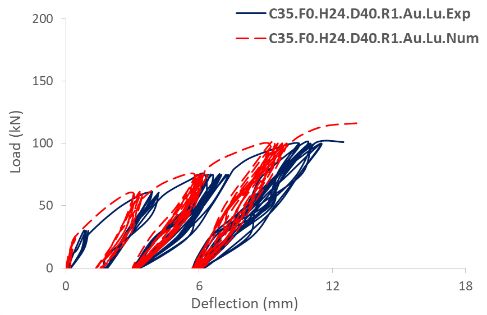
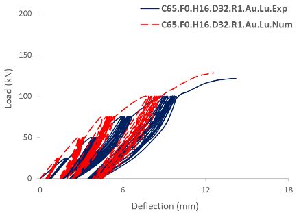
Finite Element Analysis of Two-Way Hollow High Strength Self-Compacting . . . . 757

4. Results and Discussion
General behaviour was observed for two-way hollow reinforced concrete slabs
under the effects of equivalent uniformly distributed repeated loads following three
key levels of deformations. The first level found within the elastic range where
linearly relationships were observed between load-deflection curves. The second
level (elastic-plastic stage) started as soon as the first crack initiated in the tension
face that was ranging between 0.037 mm to 0.12 mm and corresponding to load
level ranged between about 15% and 26% of the ultimate level. In this level, more
cracks were initiated and propagated at the tension face as the number of cycles or
the magnitude was increased. In addition, a linear correlation was detected in this
level between load-deflection curves with different slopes. Cracks number, as well
as cracks width, was raised and moved to the corners of the reinforced concrete
slabs. Finally, a further increase in the numbers of cycles of the repeated load or
the magnitude of the applied load was resulting in an excessive reduction in the
stiffness followed by collapse.
 The experimental outcomes showed that constructing two-way hollow slabs
with voiding ratio up to 24% using two-way piping systems led to reducing the
ultimate loading capacity by about 20% [14]. Furthermore, the results showed that
is possible to compensate the weakness that occurs in the structural performance of
two-way hollow reinforced concrete slabs by different options including using fiber
reinforced concrete, increasing the main reinforcement, using mixtures of high
strength concrete or distributing the two-way piping systems out of the location of
the maximum stresses [15].
 The nonlinear FEA of two-way hollow reinforced concrete slabs showed
acceptable agreement with the experimental behaviour. The results also
demonstrated that the FE first cracking loads were higher than the experimental
cracking loads by about 4% to 14%. That could be due to the higher the
homogenous of FE models. Moreover, FE ultimate loads were higher than the
ultimate experimental loads by about 2% to 15% while the FE central deflections
at the ultimate level were lower than those of the experimental study by about 3% to
13%, except for C35.F0.H24.D40.R1.A0.Lu that had higher FE central deflection than
experimental results by about 6%. Besides, the models of finite element method showed
stiffer behaviour than real models in the pre-cracking segment of the load-deflection
curve and showed either similar or stiffer performance in the post-cracking segment, as
presented in Table 2 and Fig. 7. Finally, A deflection profile was also drawn at different
levels of loading for the experimental and FE methods for two-way hollow slab
(C65.F0.H16.D32.R1.Au.Lu that had ultimate experimental deflection of 14.20 mm and
ultimate numerical deflection of 12.60 mm) as an example to check the efficiency of
the offered model, are shown in Fig. 8.

Journal of Engineering Science and Technology February 2021, Vol. 16(1)
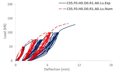
758 W. A. Tameemi and N. A. Alwash

 Fig. 7. Experimental vs. numerical load-
 deflection curves of two-way hollow RC slabs.

Journal of Engineering Science and Technology February 2021, Vol. 16(1)
Finite Element Analysis of Two-Way Hollow High Strength Self-Compacting . . . . 759

Table 2. Experimental vs. numerical mechanical behaviour of two-way RC slabs.
 _ _ _ _ _ _ _
Model ID
 _ (kN) (kN) _ (kN) (kN) _
C65.F0.H0.D0.R1.A0.Lu 1.042 142.4 149.81 1.052 17.52 15.96 0.91
C65.F0.H8.D20.R1.Au.Lu 1.094 125.5 130.02 1.036 16.14 13.97 0.87
C65.F0.H8.D32.R1.Au.Lu 1.102 128.3 131.91 1.028 14.52 12.84 0.88
C65.F0.H8.D40.R1.Au.Lu 1.101 132.1 134.89 1.021 13.34 11.71 0.88
C65.F0.H16.D32.R1.Au.Lu 1.066 121.6 128.23 1.054 14.20 12.60 0.89
C65.F1.5.H16.D32.R1.Au.Lu 1.064 180.3 190.43 1.056 14.82 14.35 0.97
C65.F0.H16.D32.R2.Au.Lu 1.055 172.6 183.23 1.06 10.32 9.22 0.89
C65.F0.H16.D32.R1.Anu.Lu 1.113 124.5 137.31 1.102 13.60 12.08 0.89
C65.F0.H24.D40.R1.Au.Lu 1.122 115.2 125.22 1.087 13.83 12.74 0.92
C35.F0.H0.D0.R1.A0.Lu 1.134 128.2 131.38 1.025 11.23 9.94 0.88
C35.F0.H24.D40.R1.A0.Lu 1.125 101.1 116.21 1.149 12.51 13.20 1.06

 Fig. 8. Numerical vs. experimental
 deflection profile of C65.F0.H16.D32.R1.Au.Lu.

5. Conclusions
This paper was designed to examine the structural performance of two-way hollow
high strength reinforced concrete slabs using finite element analysis by
ABAQUS/Standard 2017 under the influences of uniformly distributed repeated
loads. Eleven models of dimensions (880 × 880 × 80 mm) consisting of two solid
reinforced concrete slabs and nine two-way hollow reinforced concrete slabs that
were made-up using an innovative type of two-way plastic piping system, were
considered in this paper. This new type of two-way piping system could be
fabricated using networks of plastic pipes and their fittings. Main findings include:
 • It is possible to construct two-way hollow reinforced concrete slabs with
 voiding ratio up to 24% using two-way piping systems with keeping about
 80% of the original ultimate loading capacity.
 • It is possible to compensate the reduction that occurs in the strength of two-
 way hollow reinforced concrete slabs by using fiber reinforced concrete,
 increasing the ratio of main reinforcement, using mixtures of high strength
 concrete or distributing the two-way piping system out of the location of the
 maximum stresses.

Journal of Engineering Science and Technology February 2021, Vol. 16(1)
760 W. A. Tameemi and N. A. Alwash

 • Using nonlinear finite element analysis by ABAQUS/Standard 2017 in
 conducting the mechanical behaviour of two-way hollow reinforced concrete
 slabs showed acceptable results with a maximum difference in cracking loads,
 ultimate loading capacity and central deflection of about 14%, 15% and 13%,
 respectively in comparison with the experimental results.

 Nomenclatures

 Anu Distributing the two-way piping system out of the location of
 maximum stresses
 Au Distributing the two-way piping uniformly
 C35 Concrete with normal strength
 C3D8R An 8-node linear brick with reduced integration and hourglass
 control
 C65 Concrete with high strength
 D0 Solid slab
 D32 Pipe diameter equal to 32 mm
 D40 Pipe diameter equal to 40 mm
 F0 Concrete slab with no fibers
 F1.5 Concrete slab with (1.5%) micro steel fiber
 H0 Solid slab
 H16 Two-way hollow slab with 16% of voids
 H24 Two-way hollow slab with 24% of voids
 Lu Load type is equivalent uniformly distributed repeated load
 P_(cr_Exp) Experimental first cracking load, kN
 P_(cr_Num) Numerical first cracking load, kN
 P_(u_Exp) Experimental ultimate load, kN
 P_(u_Num) Numerical ultimate load, kN
 R1 The ratio of main reinforcement equal to 0.002355
 R2 The ratio of main reinforcement equal 0.004710
 T3D2 A 2-node linear 3-D truss

 Greek Symbols
 ρ The ratio of main reinforcement
 δ_cu_Exp Experimental ultimate deflection, mm
 δ_cu_Num Numerical ultimate deflection, mm
 Abbreviations
 ABAQUS Finite element package
 ABAQUS Finite element package
 ASTM American Society for Testing and Materials
 EUDRL Equivalent uniformly distributed repeated load
 EUDRL Equivalent uniformly distributed repeated load
 FEA Finite element analysis
 FEA Finite element analysis
 IQS Iraqi Quality Standardization

References
1. Yang, W.; Yang, Y.; Jiang, P.; and Han, B. (2013). Experimental study on
 mechanical property of corner columns supported reinforced concrete

Journal of Engineering Science and Technology February 2021, Vol. 16(1)
Finite Element Analysis of Two-Way Hollow High Strength Self-Compacting . . . . 761

 honeycombed-core girderless floor. The Open Civil Engineering Journal,
 179-188.
2. Hai, L.V.; Hung, V.D.; Thi, T.M.; Nguyen-Thoi, T.; and Nguyen, P.T. (2013).
 The experimental analysis of bubbledeck slab using modified elliptical balls.
 Proceedings of the Thirteenth East Asia-Pacific Conference on Structural
 Engineering and Construction. Sapporo, Japan.
3. Wariyaton, N.G.; Haryanto, Y.; and Sudibyo, G.H. (2017). Flexural behaviour
 of precast hollow core slab using PVC pipe and styrofoam with different
 reinforcement. Sustainable Civil Engineering Structures and Construction
 Materials, 171, 909-916.
4. Al-Yassiri, L.S.H. (2017). Behavior of voided reinforced concrete slabs with
 carbon fiber reinforced polymer bars. Ph.D. Thesis. University of Babylon,
 Babylon, Iraq.
5. Rajeshwaran, R.; Yamini, V.; Nivedha, D.G.S.; and Madhu, B.A. (2018).
 Experimental evaluation of concrete slab using hollow steel pipes. Civil
 Engineering Research Journal, 5(4), 00161-00164.
6. Sagadevan, R.; and Rao, B.N. (2019). Effect of void former shapes on one-way
 flexural behaviour of biaxial hollow slabs. International Journal of Advanced
 Structural Engineering, 11, 297-307.
7. Sabr, Y.N.; Jarallah, H.K.; and AbdulKareem, H.I. (2019). Improving shear
 strength of thick hollow core slabs by using lightweight high strength concrete
 produced from recycled crushed clay brick and iron powder waste. Journal of
 Engineering and Sustainable Development, 23(6), 128-146.
8. IQS No. 5 (1984). Portland cement. Central Agency for Standardization and
 Quality Control. Baghdad, Iraq.
9. ASTM C136 / C136M – 14 (2014). Standard test method for sieve analysis of
 fine and coarse aggregates. American Society for Testing and Materials.
10. IQS No. 45 (1984). Aggregate from natural sources for concrete and
 construction. Central Agency for Standardization and Quality Control.
 Baghdad, Iraq.
11. ASTM C1240 – 15 (2015). Standard specification for silica fume used in
 cementitious mixtures. American Society for Testing and Materials.
12. ASTM C494 / C494M – 17 (2017). Standard specification for chemical
 admixtures for concrete. American Society for Testing and Materials.
13. ASTM A1064 / A1064M - 18a (2018). Standard specification for carbon-steel
 wire and welded wire reinforcement, plain and deformed, for concrete.
 American Society for Testing and Materials.
14. Tameemi, W.A.; and Lequesne, R.D. (2015). Correlations between
 compressive, flexural, and tensile behaviour of self-consolidating fiber
 reinforced concrete. Master thesis. University of Kansas Center for Research,
 Inc., Lawrence, KS, USA.
15. Tameemi, W.A. (2020). Nonlinear behaviour of two-way hollow high strength
 self-compacting fiber reinforced concrete slabs under repeated load. Ph.D
 thesis. University of Babylon, Babylon, Iraq.

Journal of Engineering Science and Technology February 2021, Vol. 16(1)
You can also read