MODIFIED WEB SLENDERNESS CLASSIFICATION FOR COMPOSITE GIRDERS IN CODE PROVISIONS.
←
→
Page content transcription
If your browser does not render page correctly, please read the page content below
International Journal of GEOMATE, April., 2021, Vol.20, Issue 80, pp.168-175
 ISSN: 2186-2982 (P), 2186-2990 (O), Japan, DOI: https://doi.org/10.21660/2021.80.j2068
 Geotechnique, Construction Materials and Environment

 MODIFIED WEB SLENDERNESS CLASSIFICATION FOR
 COMPOSITE GIRDERS IN CODE PROVISIONS.

 Ahmed Mohamed AbdElrahman1, *Manar Maher Hussein2 and Walid Abdel-Latif Attia3
 1,2,3
 Faculty of Engineering, Cairo University, Egypt

 *Corresponding Author, Received: 30 Dec. 2020, Revised: 25 Jan. 2021, Accepted: 06 Feb. 2021

ABSTRACT: Composite girder is one of the main structural systems used in bridges and buildings. The same
slenderness limits requirements for steel sections are used also for the composite sections in most specifications
without considering the effect of concrete slabs. In fact, for composite sections under positive moments, the
compression concrete slab restrains the buckling of the top flange and the compressed part of the web, in
addition the steel plates behave plastically up to failure. By accounting concrete slabs attached to the steel
compression elements, the section may be placed in more favorable class. The main objective of this study is
to verify a reasonable relaxed slenderness limits for steel compact composite sections compared to compact
steel section only and investigate the influences of the span length of girder and the concrete strength of slab,
on the slenderness limits. An extensive parametric study using ANSYS, a commercial finite element (FE)
software, was held using different web slenderness, various concrete strengths and girder lengths. The section
classifications were evaluated, and the results were compared to the Egyptian code, Eurocode and AASHTO.
A new relaxed equation and new classification limits have been developed considering the effect of the concrete
slab strength.

Keywords: Composite girders; Web slenderness; Ultimate flexural strength; Egyptian Code; ANSYS

1. INTRODUCTION capacity of simply supported composite beams
 considering various degrees of shear connection.
 . For full integration composite compact section with
 Considering its influence on reduction in cost high yield strength steel section, the failure can
and time, composite steel-concrete girders, occur due to concrete crushing or steel plastic
especially for medium to large bridges’ spans and failure [5]. However, for compact sections with
multi-story steel wide frames, have achieved high higher steel yield strengths, crushing of the concrete
market share. Composite girders are horizontal slab may take place before reaching section full
structures, in most cases, consisting from steel and plastic moment capacity. All the girders were
concrete. For simple composite girders, the steel designed using current codes such as AASHTO [6]
section is located in tension region and the concrete and EUROCODE [7] to predict the flexural strength
slab located in the compression region. These two of sections with Dp/Dt in the linear range ( Figs.1-
materials connected by metallic devices called 2), where Dp is the position of the plastic neutral
shear connectors. Gupta [1] stated that most axis and Dt is the total depth of section. A proposed
available codes’ formulas are based on linear equation was expressed as a function of Dp/Dt
experimental techniques not accounting the ratio[5]. Duc and Okui [8]and [9], studied the
material or geometric nonlinearities and not influence of using composite high strength steel
considering the effect of the concrete slab in with ultimate strength equals to 500 N/mm2 and 700
composite sections. Taleb and Ammari [2] N/mm2 on the web slenderness limits. They
indicated that the theoretical simplicity of supports concluded that using high strength steel to both
is fulfilled by certain dimensions of flanges. The homogeneous and hybrid sections increase
concrete slab fixation at the composite section significantly the web slenderness limits. The
eliminates the web local buckling length at least in behavior of composite girders under combined
loading direction. An in-plane deformation happens negative moment and shear and with web local
axially before transverse buckling and shear buckling effects was investigated in [10]and [11].
deformation as concluded by Musa [3]. Thus, In this study, the concrete strength was
concrete slab also provides practically more in considered as a factor to produce new equation and
plane resistance for the axial deformation compared classifications limits. The research objectives were
to the steel section only. Liu [4]explained that some to achieve a good understanding for the types of
of the empirical methods could be more applicable predominate failure modes of Steel-Concrete
and non-conservative in accounting the flexural composite girders and provide a less strengthen

 168
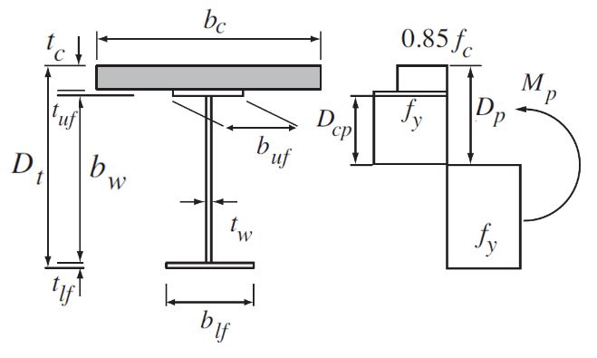
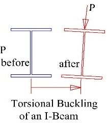
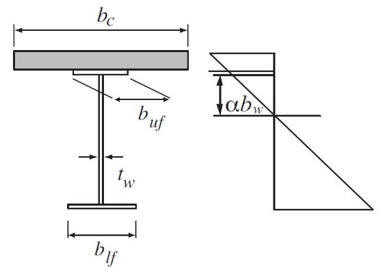
International Journal of GEOMATE, April., 2021, Vol.20, Issue 80, pp.168-175

design tendency. This was implemented by in Fig.3. While according to [7], the composite
verifying a reasonable slenderness limits for steel sections are classified into four categories (Table 1),
compact composite sections relaxed compared to allowing using plastic design method only for Class
those for compact steel section only and accounting 1 and 2 sections, while [12] and [6] allow it for the
for the material plasticity behavior, buckling and compact section only. Section classifications are
concrete crushing. Also, by investigating the effects shown in Table1, with parameters as defined in the
of girder span length and slab concrete strength on relevant codes and Figs. 1-3; My, Mp and Mmax are
the slenderness limits and applying these studies to yield, plastic and ultimate moments respectively.
the Egyptian code of practice for steel construction While bw, tw, ε and Ψ are web height, web thickness,
[12]. Two yield steel strengths (240 and 360N/mm2) maximum strain and ratio between upper to lower
were applied in[13]. The present study was limited flanges stresses respectively. While Dcp is the depth
to high yield steel strength of 360N/mm2, not of web in compression and is the ratio between
extended to study connection failure or slipping of the location of axis of bending to the web height. In
shear connectors, full interaction composite. In fact, most available codes’ formulas are based on
addition, this study is limited to shored composite linear experimental techniques, not accounting the
girders and not extended to the influence to the material or geometric nonlinearities and not
effect of the initial moment or residual stresses considering for the effect of concrete slab in
effect. composite sections [1].

 Fig .3 Moment capacities of sections [15]

 2.2 Structural Buckling and plastic behavior

 Buckling is one of the most critical failure
 Fig. 1 Stress distribution in compact section [14]
 modes in steel structures under compression or
 bending loads [16]. The main types of local
 buckling behaviors of the steel elements were
 shown in Fig. 4 [17]. These sections can be regarded
 as a combination of individual plate elements
 connected together to form the required shape.
 Different types of overall structural buckling were
 presented in Fig. 5 [18]. All codes and standards
 consider the buckling as one of the main governing
 factors to account the strength of the steel structural
 elements although that the total collapse not
 Fig. 2 Theoretical strain in compact section [14] necessarily developed by buckling of an edge-
 supported thin plates and the plates can generally
2. METHODOLOGY AND VALIDATION support more loads greater than critical local
 buckling loads load.
 In order to accomplish the study, finite element
analysis using a commercial finite element software
ANSYS. This software is able to simulate the
overall non-linear plastic behavior of simply
supported composite beams including buckling of
the steel elements and cracking of the concrete slab.

2.1 Codes Classifications
 Specifications [12] and [6] classified steel
sections according to buckling behaviours to three
types, compact, non-compact and slender as shown Fig. 4 Local buckling a) open b) closed section.

 169
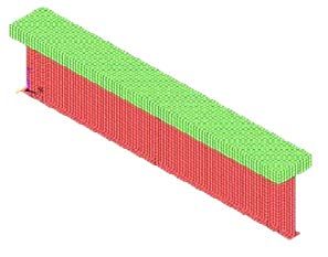
International Journal of GEOMATE, April., 2021, Vol.20, Issue 80, pp.168-175

Table 1: Section Classifications AASHTO [6], EUROCODE [7] and ECP-LRFD [19]
 Section Class
 Design Code Definitions Web Slenderness Limits
 Compact Mmax > Mp
 2 � ≤ 3.76� ⁄
 AASHTO Non-Compact Mp > Mmax ≥My
 (2005) 2 � ≤ 5.7� ⁄

 Slender Mmax < My Other than those Above
 Class 1 Mmax ≥ Mp 36ε/α for α ≤ 0.5
 � ≤�
 Sufficient 396ε/(13α − 1) for α > 0.5
 Rotational
 Capacity
 Class 2 Mmax ≥ Mp 41.5ε/α for α ≤ 0.5
 � ≤ �
 Limited 456ε/(13α − 1) for α > 0.5
 EUROCODE Rotational
 (2001) Capacity
 Class 3 Mmax ≥ My 42ε/(0.67 + 0.33ψ) for ψ < −1.0
 � ≤ �
 62ε/(1 − ψ)�−ψ for ψ ≥ −1.0

 Class 4 Mmax < My Other than those Above

 Compact Mmax > Mp
 ⎧699�� /(13α − 1) for α ≤ 0.5
 ECP-LRFD � ≤
 ⎨ (36.6/α )/ for α > 0.5
 (2012) �
 ⎩

 Non-Compact Mp > Mmax ≥My
 ⎧111/(1 − ψ)�−ψ /� for ψ ≤ −1.0
 � ≤
 ⎨ 222/ /(2 + ψ) for ψ > −1.0
 �
 ⎩
 Slender Mmax< My Other than those Above

 • Slender cross-sections when the local buckling
 prevent ultimately the reaching of the yield.
 Web slenderness is one of the most important
 influence on flexural strength of composite girder.

 2.3 Numerical Study
Fig.5 Types of overall buckling
 For Steel Plates, ANSYS Three-dimensional four-
 node shell element, SHELL43 were used with three
 For plate girders consisting from three plates, translations in x, y and z in each node to achieve the
considering (b) as plate length and (t) as plate compatibility condition with translation in x, y and
thickness and β=b/t. Sections of steel structures can z in adjacent brick element to it. An eight-node solid
be classified according to plastic behavior (Fig. 3): element, Solid65, was used to model the concrete
• Plastic sections, when section can reach its full- with three degrees of freedom at each node–
 plastic moment Mp and allow rotation at or translations in the nodal x, y, and z directions. The
 after the plastic moment. element is capable of plastic deformation, cracking
 in three orthogonal directions, and crushing. Mesh
• Compact cross-sections, when section can
 dimensions of both elements types for the section
 reach its full-plastic moment Mp but the equals to 50mm in both directions. Figure 6 shows
 rotation could not be developed. the overall FE model. Constraining the steel girder
• Non-Compact cross-sections, when local and concrete slab at the connected joints in the three
 buckling prevents the section from reaching its transitions directions simulated the full integrated
 full-plastic moment Mp. simply supported girder composite action. The

 170

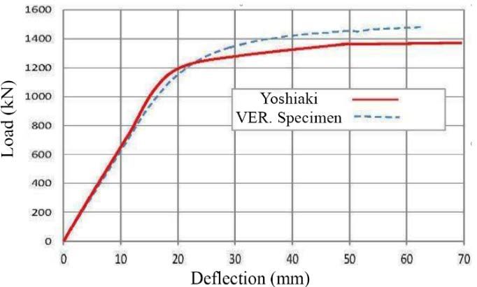
International Journal of GEOMATE, April., 2021, Vol.20, Issue 80, pp.168-175

 static loading applied was chosen to be in the shape strength 450 MPa and 28% elongation) while the
 of point loads which were applied by means of concrete strength of the slab is 45 MPa. A 9.00m
 displacement control method, the loads were span girder was used as a reference to validate the
 increased incrementally. Vertical displacements present ANSYS F.E. method in this study. Fig. 9
 were applied at five adjacent bottom joints in the shows a comparison of the Load – displacement
 middle section’ lower flange of the span to curves of the Okui’s [20] experimental results and
 distribute the effect of loading (Fig. 7-a). The strain the ANSYS verification model; the figure showed a
 values were considered by adding the Von mises good agreement in the results of the two specimens
 elastic strains to the equivalent plastic strains (less than 5% difference).
 produced by ANSYS finite elements results. Figure
 7-b shows the boundary conditions of supports; one
 end of the girder was restrained against transitional
 movements in the three orthogonal directions X, Y
 and Z, while the other was restrained in Y and Z
 directions. The restraints were performed nearly at
 the center of gravity of the steel structure section.

 Fig. 8 Reference Specimen [20]

 Fig. 6 Overall FE model for the composite section

 Fig. 9 Compared Load-Deflection relationship

 3. PARAMETRIC STUDY
 (a)
 Table 2 shows the properties of the specimens
 used in this study. The two groups depending on the
 concrete strengths, 20 N/mm2 and 40 N/mm2, (0.2
 and 0.4 t/cm2), were divided to three types
 referenced to the used steel web width/thickness
 plate original slender classification: 13, 23 and 33.
 At this study, Fyw and Fyf are yield strength of the
 specimen’s web and flanges respectively, were
 (b) equal both to 360N/mm2. The original section
Fig. 7 Boundary Conditions a) Loading nodes in classification according to ECP-LRFD [12] steel
 numerical model, b) Support boundary conditions. structure classification was shown also. All
 specimens’ lower flanges were 30mm thickness and
 2.4 Validation of the Model the upper flanges with 5mm thickness. Specimens
 were chosen to fulfill that the linear plastic neutral
 The reliability of the FE model of composite axis is located on the steel upper web. Span length
 beams is validated by comparison with shortest specimen’s length, 4.5 m, A-specimens,
 experimental study. The reference specimen [20] represented average of the maximum length
 was tested experimentally and analytically using limiting laterally unbraced length for inelastic
 DIANA, a finite element software program. Figure lateral torsion buckling of steel structural girders, Lr
 8 shows the girder specimens with a span length of as per [12]. Other spans, 9.00m, B-specimens, and
 9.00 m loaded in the middle of the specimen. I 18.00m, C-specimens, were duplicated of the
 shaped steel girders were designed with SM400A shortest length. Concrete slab width, 600 mm,
 grade steel (Yield strength 300 MPa, Ultimate equivalent to three times the upper flange width

 171
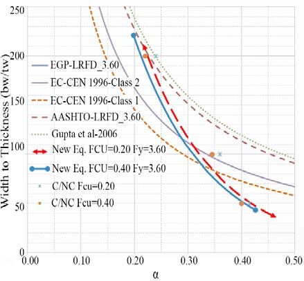
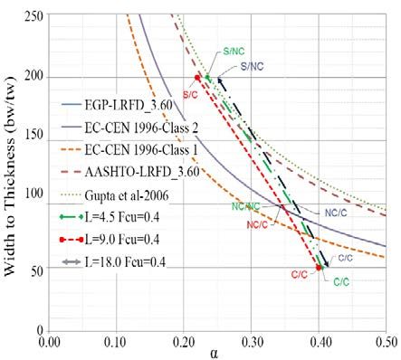
International Journal of GEOMATE, April., 2021, Vol.20, Issue 80, pp.168-175

(Bf=200mm) and one eighth of the shorter span length, while the depth was 200mm.
Table 2- Specimens Properties

 L Web bw tw bw/tw Status

 m mm mm mm ECP
 LRFD
 20A13 4.50 1000X20 1000 20 50 C
 Conc. Strength 0.40 Spec. Conc. Strength 0.20 Spec.

 20A23 4.50 1000X10 1000 10 100 NC
 20A33 4.50 1000X5 1000 5 200 S
 20B13 9.00 1000X20 1000 20 50 C
 20B23 9.00 1000X10 1000 10 100 NC
 20B33 9.00 1000X5 1000 5 200 S
 20C13 18.00 1000X20 1000 20 50 C
 20C23 18.00 1000X10 1000 10 100 NC
 20C33 18.00 1000X5 1000 5 200 S
 40A13 4.50 1000X20 1000 20 50 C
 40A23 4.50 1000X10 1000 10 100 NC
 40A33 4.50 1000X5 1000 5 200 S
 40B13 9.00 1000X20 1000 20 50 C
 40B23 9.00 1000X10 1000 10 100 NC
 40B33 9.00 1000X5 1000 5 200 S
 40C13 18.00 1000X20 1000 20 50 C
 40C23 18.00 1000X10 1000 10 100 NC
 40C33 18.00 1000X5 1000 5 200 S

4. RESULTS AND DISCUSSIONS classified non-compact and even slender sections
 have been upgraded in performance to act as a
 Table 3 summarizes the results of flexural compact section reaching its relevant plastic
moments for the specimens. Calculated plastic and moment value regardless the web thickness. For
yield moments in addition to flexural moments at originally classified compact sections of the
failure for the F.E. specimens were shown. Yield shortest length, 4.50m, A-specimens, the ultimate
and plastic moments were determined analytically moments were less than the plastic capacity
for each section using the first principal’s moments. This could be referred to that for shorter
assumptions. Mu represented the minimum of specimens, the failure criteria governed could be
ANSYS FE’s steel ultimate moment at failure or the predominated by the capacity of the shear strength
moment corresponding to plain concrete maximum of the section and shear buckling and would not
allowable strain limit equaled to the second allow enough rotation. the predominated failure is
boundary limit, 0.0035, whichever less. Maximum most cases related to shear failure not for moment.
moment at the first concrete cracking was For longer spans of 18.0m, C-specimens, the
considered as the local buckling beginning of the compact sections remained compact for the two
failure process propagation. This was due that after used types of concrete strengths, while for the non-
cracking moment, the section could not still act with compact section even if it allowed more rotations,
its full restraint actions to out of plane effects for the but the ultimate moment, defined with respect to
upper flange and the part of web under compression. concrete crushing, did not reach the plastic moment
Then, the new status of the sections was based on for higher concrete strength. This could be also
comparing Mu to My and Mp. If Mu equaled or related to the influences of out of plane effects
exceeded the value of the My, this was an indication under the conditions of dimensions of the concrete
for reaching the non-compact limit while if it slabs and steel sections used in this study. Fig.10
reached Mp this was considered still within the shows the relation between slenderness limits
compact limits. Otherwise, if the value of Mu was represented by web width/web thickness and the
below My value, it was considered in the slender result value of α evaluated from the finite element
classification category. analysis. Fig.11 shows the moment verses rotation
 For the medium span specimens 9.00m, B- relationships for C’s specimen which indicated the
specimens, it was observed that the initially higher level of ductility performance with respect to

 172
International Journal of GEOMATE, April., 2021, Vol.20, Issue 80, pp.168-175

the others specimens’ lengths. It was observed from Fig. 10 that the three variable specimens with
Table 3: Specimens Results

 Moments N.mm (x10E5)
 (ton.cm)
 My Mu Mp Mu/My Mu/Mp Mp/My ECP- New
 Status Status
 20A13 3129.4 3600.0 4325.5 1.15 0.83 1.38 C NC
 Concrete Strength 0.20

 20A23 2346.1 2961.5 3423.5 1.26 0.87 1.46 NC NC
 20A33 1902.8 2005.0 2969.5 1.05 0.68 1.56 S NC
 20B13 3129.4 5060.8 4325.5 1.62 1.17 1.38 C C
 Spec.

 20B23 2346.1 3670.0 3423.5 1.56 1.07 1.46 NC C
 20B33 1902.8 3201.6 2969.5 1.68 1.08 1.56 S C
 20C13 3129.4 4535.0 4325.5 1.45 1.05 1.38 C C
 20C23 2346.1 3545.3 3423.5 1.51 1.04 1.46 NC C
 20C33 1902.8 2570.6 2969.5 1.11 0.71 1.56 S NC
 40A13 3322.0 4423.1 5381.2 1.33 0.82 1.62 C NC
 Concrete Strength 0.40

 40A23 2442.5 3346.0 4300.7 1.37 0.78 1.76 NC NC
 40A33 1945.8 24567 3850.5 0.86 0.44 1.98 S NC
 40B13 3322.0 5626.0 5381.2 1.69 1.05 1.62 C C
 Spec.

 40B23 2442.5 4456.0 4300.7 1.82 1.04 1.76 NC C
 40B33 1945.8 4032.6 3850.5 2.07 1.05 1.98 S C
 40C13 3322.0 5250.0 5381.2 1.76 1.09 1.62 C C
 40C23 2442.5 3882.5 4300.7 1.18 0.67 1.76 NC NC
 40C33 1945.8 2923.5 3850.5 1.14 0.58 1.98 S NC

 Fig. 10 Specimens results for α & ⁄ relation. Fig. 11 Moment-Rotation for C’s specimens

length 9.00m behaved as a compact section Where α = ⁄ , yield strength of web in
regardless their web thickness with lowest value of α,
 N/mm2, yield strength of concrete in N/mm2,
thus these specimens were considered the base
 web maximum dimension (length) in mm,
points to evaluate the new relaxed equation as
 web minimum dimension (thickness) in mm. Fig.
clarified above. The study led to a proposed derived
 12 shows the proposed equation relative to the two
equation Eq. (1) representing the boundary limit
 concrete strength categories used in this study with
between Compact and Non-compact taking the steel
 respect to the variable codes mentioned compared
and concrete strengths into consideration.
 with other codes’ curves. It is clear that the using
 concrete slab dimensions and strength introduced
 ��0.2� �
 5.40 8
 ⁄ ≤ [350 −7.15 α ] (1) new factors totally different to steel structural
 �
 material. It is also observed that accounting

 173
International Journal of GEOMATE, April., 2021, Vol.20, Issue 80, pp.168-175

concrete slab provided a clear relaxation for the to prevent concrete crushing, this limit have to
limit requirements between compact and non- be considered in the ECP-LRFD.
compact sections: sections considered non-compact 5. Knowing that the flexural ductility is better to
in the Egyptian Code of practice reached their be observed from the rotation verses bending
compactness limit in the proposed equation. This moment curves, it was shown that the increase
will have a considerable reduction in the cost of in regularity performance was directly
composite girders construction. proportional to the specimen’s span length and
 the best specimens which show good global
 ductility performance were the longest spans.
 6. Lengths for limiting lateral unbraced for full
 plastic bending capacity (Lp), for inelastic
 lateral torsional buckling (Lr) and for using
 plastic design (Lpd) have to be revised in the
 composite section in code, as the upper flange
 is already restricted from moving and its
 strength has no effect on the compression
 behavior of the section. ECP-LRFD maximum
 lengths relative to beginning the local buckling
 for the steel structure sections is not applicable
 for composite sections.
 7. This research has offered a good preliminary
 approach, but further study is still required on
 the implication of its recommendations, to
 enlarge their scope of application to cover
 wider range of slenderness, stiffening, residual
 Fig. 12 Proposed Equation Curves stresses, shear connectors and material type of
 steel elements.
5. CONCLUSION
 6. REFERENCES
 In this study, a series of numerical analyses
were conducted using two types of concrete [1] Gupta V. K., Okui Y., and Nagai M.,
strengths with variable spans to study their effect on “Development of web slenderness limits for
the slenderness limit. Based on the results obtained, composite i-girders accounting for initial
a modified slenderness limits for composite girders bending moment,” Doboku Gakkai
are proposed. The research results are as follows: Ronbunshuu A, vol. 62, no. 4, pp. 854–864,
 2006, doi: 10.2208/jsceja.62.854.
1. ECP-LRFD is nearly similar to the Eurocode [2] Taleb C. eddine, Ammari F., Adman R.,
 class 2 in the Compact - Non-compact limits. “Analytical Study of Buckling Profile Web
 In addition, the ECP-LRFD is significantly Stability,” Struct. Eng. Mech., vol. 53, no.
 conservative compared to the obtained results 1, p. 147, 2015, doi: 10.12989/SEM.
 and also to AASHTO limits. 2014.53.1.147.
2. A new relaxed equation and new classifications [3] Musa I. A., “Buckling of plates including
 limits have been developed considering the effect of shear deformations: A hyperelastic
 effect of the concrete slab strength. This formulation,” Struct. Eng. Mech., vol. 57,
 contribution helped to improve the Egyptian no. 6, pp. 1107–1124, Mar. 2016, doi:
 code for a more accurate values and more 10.12989/sem.2016.57.6.1107.
 economic sections. [4] Liu J., Ding F. X., Liu X. M., and. Yu Z. W,
3. Gupta curve is slightly relaxed than the “Study on flexural capacity of simply
 AASHTO one at the compact- non compact supported steel-concrete composite beam,”
 limits as Gupta only considers one type of Steel Compos. Struct., vol. 21, no. 4, pp.
 concrete strength with only one length span. 829–847, Jul. 2016, doi: 10.12989/scs.
4. The increase in concrete strength has a negative 2016.21.4.829.
 influence on the slenderness limits, this is [5] Gupta V. K., Okui Y., Inaba N., and Nagai
 related to the reduction of the Dcp/Dp and to M., “Effect of concrete crushing on flexural
 the crushing of concrete. This may lead that strength of steel-concrete composite
 concrete with less compressive strength is more girders,” Struct. Eng. Eng., vol. 24, no. 2,
 economic in the composite concrete-steel 2007, doi: 10.2208/jsceseee.24.73s.
 girders. Most codes provide a limit for ductility [6] American Association of State Highway
 and Transportation Officials., AASHTO

 174
International Journal of GEOMATE, April., 2021, Vol.20, Issue 80, pp.168-175

 LRFD bridge design specifications, SI [13] Abd Elrahman A. M., “A proposal of
 units : 2005 interim revisions., 3rd ed. sections classification considering web
 Washington DC: American Association of slenderness of beam composite sections in
 State Highway and Transportation Officials, the Egyptian code.,” Cairo University, 2018.
 2005.
[7] “BS EN 1994-2:2005 - Eurocode 4. Design [14] Gupta V. K., Okui Y., and Nagai M.,
 of composite steel and concrete structures. “Development of web slenderness limits for
 General rules and rules for bridges.” composite I-girders accounting for initial
 https://shop.bsigroup.com/ProductDetail?p bending moment,” Struct. Eng. Eng., vol.
 id=000000000030187356 (accessed Dec. 23, no. 2, 2006, doi: 10.2208/jsce
 18, 2020). seee.23.229s.
[8] Viet D. and Okui Y., “Flexural Capacity of [15] “Steel Designers’ Manual, 7th Edition |
 Composite Girders: Design Equation Wiley.” https://www.wiley.com/en-
 Accounting for Bridge High Performance us/Steel+Designers%27+Manual%2C+7th
 Steels,” 2014. +Edition-p-9781119249863 (accessed Dec.
[9] Duc D. V. and Okui Y., Flexural Capacity 18, 2020).
 Accounting for SBHS500 Steel of [16] Sankar M. B. and Jacob P. A., “Comparison
 Composite Bridge Girders, vol. 54. of Design Standards for Steel Railway
 Springer Singapore, 2020. Bridges,” Int. J. Eng. Res. Appl., vol. 3, no.
[10] Men P., Zhou X., Zhang Z, Di, J. and Qin 2, pp. 1131–1138, 2013.
 F., “Behaviour of steel–concrete composite [17] “Steel Designers Manual. Fifth Edition.”
 girders under combined negative moment https://trid.trb.org/view/375463 (accessed
 and shear,” J. Constr. Steel Res., vol. 179, Dec. 18, 2020).
 p. 106508, Apr. 2021, doi: [18] Subramani T. and Sugathan A., “Finite
 10.1016/j.jcsr.2020.106508. Element Analysis of Thin Walled-Shell
[11] Bui V. T., Truong V. H., Trinh M. C., and Structures by ANSYS and LS-DYNA,”
 Kim S. E., “Fully nonlinear analysis of 2012.
 steel-concrete composite girder with web [19] ECP-201, “Egyptian Code of Practice for
 local buckling effects,” Int. J. Mech. Sci., Calculation of Loads and Forces in
 vol. 184, p. 105729, Oct. 2020, doi: Structures and Buildings.,” Cairo, 2012.
 10.1016/j.ijmecsci.2020.105729. [20] Okui Y., “Design Issues for Steel-Concrete
[12] “Egyptian Code Of Practice For Steel Composite Girders,” Earthquake, pp. 85–93,
 Construction :(Load And Resistance Factor 2011.
 Design) (LRFD) 205 Ministerial Decree No Copyright © Int. J. of GEOMATE. All rights reserved,
 359 - 2007 /.” 2012. including the making of copies unless permission is
 obtained from the copyright proprietors.

 175
You can also read