An Ultra-Thin Low-Frequency Tunable Metamaterial Absorber Based on Lumped Element

Page created by Gladys Padilla
 
CONTINUE READING
An Ultra-Thin Low-Frequency Tunable Metamaterial Absorber Based on Lumped Element
RADIOENGINEERING, VOL. 28, NO. 3, SEPTEMBER 2019                                                                               579

    An Ultra-Thin Low-Frequency Tunable Metamaterial
            Absorber Based on Lumped Element
                 GuoWen ZHANG, Jun GAO, Xiangyu CAO, HuanHuan YANG, Liaori JIDI
      Information and Navigation College, Air Force Engineering University, Fenghao Road 1st Xi’an 710077, China

   849325138@qq.com, gjgj9694@sina.com, xiangyucaokdy@163.com, jianye8901@126.com, jidiliaorikdy@163.cm

                                         Submitted January 17, 2019 / Accepted June 19, 2019

Abstract. In this paper, an ultra-thin metamaterial ab-              superimposing the different resonance modes within a unit
sorber with a stretching transformation (ST) pattern is pro-         cell [8], [9]. Additionally, the fractal metal structures [10]
posed and fabricated in the low-frequency range. The ab-             and the multilayer [11–13] were realized to design wide-
sorber is composed of dielectric layer, metal patch loading          band absorber. As a remarkable method, loading with
resistor and variable capacitor which produce its tunability.        lumped element was utilized to achieve broadband absorp-
In order to expand the tunable bandwidth, we applied the             tion [14–16]. Although many efforts towards the improve-
ST with various coefficients x and y to the unit cell pattern.       ment of the performance about MAs are flourishing, the
Measurement and simulated results show that the structure            low-frequency and broadband absorber are not easily real-
can be tuned to provide a continuously variable reflectivity         ized without lumped elements or increasing material thick-
level of less than –10 dB from 0.68 to 2.13 GHz at bias              ness.
voltages of 10–40 V. The total thickness of this absorber
                                                                           In this work, we present an ultra-thin MA with
was only λ/31 of the center frequency. Both measurements
                                                                     a stretching transformation (ST) pattern for use in
and simulated results indicate that this absorber can be
                                                                     low-frequency applications. The total thickness 6.036 mm
thin and achieve a tunable absorption simultaneously.
                                                                     is only λ/31 of the center frequency. Using the transmission
                                                                     line (TL) model, we can get the relationship between the
                                                                     resonant frequency and the real part of the input impedance.
Keywords                                                             The equivalent circuit model is introduced to analyze the
                                                                     broadband and tunable absorption for the proposed MA.
     Low-frequency, wideband, ultra-thin, ST coefficients,
                                                                     Then, we change the ST coefficients of unit cell pattern to
     tunability
                                                                     expand the tunable bandwidth. Finally, we also fabricated
                                                                     and measured the proposed ultra-thin MA. The experiment
                                                                     results are given to validate the good performance of the
1. Introduction                                                      MA.
      Metamaterial absorbers (MAs) can efficiently dissi-
pate the electromagnetic (EM) energy into heat, resulting in
significant reduction of the reflected waves along the echo          2. Design and Analysis
direction. However, limited to thickness and narrow band-
                                                                           A schematic of the proposed MA is depicted in
width at frequencies below 3 GHz, the MAs will be diffi-
                                                                     Fig. 1(a), which is composed of the dielectric substrate
cult to be used in practice applications. Thus, MAs with
                                                                     sandwiched with periodic metal electric resonator loaded
small size and broadband absorption are urgently neces-
                                                                     with resistors and capacitors and ground plane. The mate-
sary.
                                                                     rial of dielectric substrate is F4BM with dielectric constant
       The perfect metamaterial absorber [1] concept was             2.65 and the loss tangent is 0.001. Metal patch loaded with
first reported by Landy et al. In the microwave regime, this         resistors and capacitors was placed above the dielectric
seminal work soon inspired work in other frequency ranges            layer. The middle layer is air and the bottom layer is a full
from terahertz to visible regime due to their potential appli-       metallic plate. The metallic structures and ground are cop-
cation [2]. Among these MAs, since microwave MAs are                 pered with conductivity of 5.8 × 10⁷ S/m and the thickness
thinner and lighter than the traditional microwave ab-               of 0.036 mm. The MA is simulated and optimized. A full-
sorbers and can be used in military and commercial areas,            wave electromagnetic simulation is performed by using
which have been become a new research hot topic [3–7].               finite-element analysis based High Frequency Structure
So far, several methods in common have been devoted to               Simulator (HFSS 14.0). The periodic boundary conditions
accomplish the wideband absorber. For instance, the ab-              (PBCs) and Floquet port are utilized to simulate the infinite
sorption bandwidth can be broadened by constructing the              periodic cells. The resistor and capacitors are simulated
metamaterial absorber array with periodic arrangement or             using a lumped LRC model. The optimized parameters of

DOI: 10.13164/re.2019.0579                                                                                  ELECTROMAGNETICS
An Ultra-Thin Low-Frequency Tunable Metamaterial Absorber Based on Lumped Element
580      XIAO LIU, JUN GAO, XIANGYU CAO, ET AL., AN ULTRA-THIN LOW-FREQUENCY TUNABLE METAMATERIAL ABSORBER …

                                                                                           0
                                                                                           -5
                                                                                          -10                                              0.5 pF
                                                                                                                                           1 pF
                                                                                          -15

                                                                                   (dB)
                                                                                                                                           2 pF
                                                                                y
                                                                                t         -20                                              3 pF
                                                                                i
                                                                                v
                                                                                i
                                                                                t         -25                                              4 pF
                                                                                c                                                          5 pF
                                                                                e
                                                                                l
                                                                                f
                                                                                e
                                                                                          -30
                                                                                R         -35
                                                                                          -40
                                                                                          -45
                                                                                             0.5     1.0        1.5     2.0            2.5          3.0
                                y  m  Acos  ax                                                          Frequency(GHz)

                                                                                           0
                                                                                   (b)-5
                                                                                                                                300 Ω
                                                                                        -10
                                                                                                                                600 Ω
                                                                                        -15                                     900 Ω

                                                                                 (dB)
                                                                               y        -20                                    1200 Ω
                                                                               t
                                                                               i                                               1500 Ω
                                                                               v
                                                                               i
                                                                               t
                                                                               c
                                                                                        -25
                                                                               e
                                                                               l
                                                                               f
                                                                               e
                                                                                        -30
                                                                               R        -35
                                                                                        -40
      Fig. 1. Schematic geometry of the MA. (a) The geometry of                         -45
              the unit cell. (b) The curve of metallic plate.                              0.5       1.0        1.5     2.0        2.5          3.0
                                                                                                            Frequency(GHz)
metallic structures are as follows: p = 30, h1 = 1, h2 = 5,                   Fig. 2. Simulated reflectivity of the MA with the value of one
w = 2, g = 1, m = 14, A = 12, (units: mm) and x = 0.8, y = 1,                         parameter changed while the values of others
a = π/10. Figure 1(b) shows the boundary curve function of                            unchanged: (a) R, (b) Cv.
metallic plate.
      In the simulation process, the master-slave boundary
is applied to replicate an infinite planar array, and the inci-
dent wave is a plane wave with a linear polarization along
the (–z) direction. Then, the absorbance of MA A(ω) =
1 – T(ω) – R(ω) is calculated using the frequency-depen-
dent transmittance T(ω) = |S21(ω)|2 and reflectance R(ω) =
|S11(ω)|2 obtained from the simulation. The transmission is
zero (T(ω) = |S21(ω)|2 = 0) attributed to the metallic plate
without patterns on the bottom layer. Thus, the absorbance
can be calculated using A(ω) = 1 – R(ω). In effective
medium theory, effective permittivity ( = ' + j'') and                     Fig. 3. Equivalent circuit of MA. (a) Equivalent circuit model.
                                                                                      (b) Simplified equivalent circuit model.
effective permeability (μ = μ' + jμ'') are generally used to
analyze absorptivity, because the characteristic impedance                    The distributed parameters Ld and Cd are constant
of a material can be defined as Z() = [μ()/()]½. But in              which is determined by the structure with x = y = 1. The
some cases, electromagnetic parameters are not readily                   values of lumped elements are R and Cv, respectively. The
available. So the TL model is a powerful tool to interpret               real part of ZMA can be substituted with a resistor R', and
this structure.                                                          the imaginary part of ZMA is a capacitor C'.  is the angular
                                                                         frequency of the electromagnetic wave. R' and C' are de-
      From Fig. 2(b), we realized that the resonance state
                                                                         scribed by:
exists and may be important for deep absorption. With
R = 600 Ω, the absorbability was relatively good. Fig-                                                   R                         (2)
                                                                                         R'                          ,
                                                                                                Cd  CV  R 2 2  1
                                                                                                          2
ure 2(a) shows the resonance frequency varies with capaci-
tance when R = 600 Ω. To numerically analyze the absorp-
tion performance, we establish an accurate model for MA.                                            Cd  CV               
                                                                                     C' 1                         Ld 2  .                            (3)
Figure 3(a) shows the equivalent circuit model of MA
                                                                                             Cd  CV   1 R 
                                                                                                         2     2 2
based on TL theory [17]. By derivation, the equivalent im-                                                                 
pedance of MA can be expressed by the following formula:                       Figure 3(b) shows the simplified equivalent circuit
Z MA                                                                    model. The resonance frequency f of the simplified circuit
                                                                         is described as:
           R                     1          Cd  C V              
                                                          Ld 2  .
 Cd  C V 
               2
                   R  1
                    2   2
                                j   Cd  CV   1 R 
                                                 2     2 2                                                 1  C ' L ' C ' 2 R '2 
                                                                                                 f                                  .                  (4)
                                                                  (1)                                               2
An Ultra-Thin Low-Frequency Tunable Metamaterial Absorber Based on Lumped Element
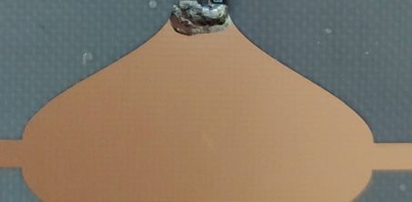
RADIOENGINEERING, VOL. 28, NO. 3, SEPTEMBER 2019                                                                                                                                           581

     According to (2), (3), (4), the real of equivalent                                                                     500
                                                                                                                                                                        300 Ω
impedance at resonance frequency can be expressed by the                                                                    400
                                                                                                                                                                        600 Ω
                                                                                                                            300
following formula:                                                                                                                                                      900 Ω
                                                                                                                            200

                                                                                                           ZMA(Ω)
                                                                                                                                                                       1200 Ω
                                                         1
                                   Re  Z MA   1  2 2 2 .
                                                                                                                            100
                                                                                         (5)                                                                           1500 Ω
                                                    4 f C ' R '                                      y
                                                                                                      r
                                                                                                      a
                                                                                                                                 0
                                                                                                      n
                                                                                                      i
                                                                                                                           -100
      ST is applied to the unit cell pattern. The size of the                                         g
                                                                                                      a                    -200
                                                                                                      m
unit cell is (x × P),(y × P), where P is the basic size before                                        I                    -300

ST and x and y are the ST coefficients on each side. The                                                                   -400
                                                                                                                           -500
topological structure of the MA pattern significantly affects                                                                  0.5         1.0       1.5         2.0      2.5        3.0
the resonant frequency of the absorber. A larger unit cell                                                                                       Frequency(GHz)
will have a lower resonance frequency. Ld and Cd represent                                                                 2.0
the distributed parameters, including inductance and capac-
itance. When the input impedance of the MA matches with                                                                    1.8
that of free space, the real part will be 377 Ω and the imagi-

                                                                                                        fresonance (GHz)
nary part will be 0. According to (2), (3), (5), the resonance
frequency f and the real part at resonance Re(ZMA) are func-                                                               1.6

tions of Ld, Cd, Cv, and R. In this case, the resonance fre-
quency f and Re(ZMA) depend only on the lumped elements                                                                    1.4
Cv and R.
      The resonance frequency f varies with the capacitance                                                                1.2
                                                                                                                             300           600             900         1200        1500
of the varactor Cv as shown in Fig. 4.When the value of                                                                                           resistance(Ω)
resistance was fixed at 600 Ω, the simulated curve with                                             Fig. 5. The curves of f and R: (a) Calculated by the HFSS.
various Cv was shown in Fig. 4(a), which coincided well                                                     (b) Simulated results calculated by using the TL model.
with the calculated curve. The calculated curve of f–Cv in
Fig. 4(b) was calculated according to (4), which described                                           The relationship between the impedance Real(ZMA)
that the resonant point is a descending function of Cv.                                        and R, Cv are depicted in Fig. 6. It can be seen from
      Figure 5 shows the relationship between f and R. With                                    Fig. 6(a) that the real part of impedance at resonant fre-
Cv = 1 pF, we get R-f curves when R changes from 300 to                                        quency is almost constant with the varying of Cv. Fig-
1500 Ω, as shown in Fig. 5(a). Figure 5(b) shows the simu-                                     ure 6(b) shows the relationship between Real(ZMA) and R
lated results for various R by the TL model. The resulting                                     when the MA resonates. From this we can see that the real
curve both simulated and calculated described that varying                                     part of the impedance varies sharply with the value of re-
R affects f only slightly. So we can approximate f as just                                     sistance.
a function of Cv.
                                                                                                       (a) 400                                                                  0.5 pF
        (a) 250
            200
                                                                          0.5 pF                                           350                                                  0.8 pF
                                                                          0.8 pF                                           300                                                  1 pF
                            150                                            1 pF                                                                                                 3 pF
                                                                                                                           250
                            100                                            3 pF                                                                                                 5 pF
         ZMA(Ω)

                                                                                                              ZMA(Ω)

                                                                           5 pF                                            200
                             50
       y                       0                                                                      l                    150
       r
       a
       n                     -50
                                    a b                  c     de                                     a
                                                                                                      e                    100
       i                                                                                              R
       g
       a                    -100                                                                                             50
       m
       I                    -150                                                                                                 0
                            -200                                                                                            -50
                            -250                                                                                               0.5         1.0       1.5         2.0      2.5        3.0
                                0.5           1.0        1.5        2.0     2.5    3.0                                                           Frequency(GHz)
                                                    Frequency(GHz)
                                                                                                                           1000
                            2.0
                                   e'                                                                                       900                                         300 Ω
                            1.8                                                                                                                                         600 Ω
                                    d'                                                                                      800
                                                                                                                                                                        900 Ω
                            1.6      c'                                                                                     700
                                                                                                                                                                        1200 Ω
         fresonance (GHz)

                                                                                                                            600
                                                                                                          ZMA(Ω)

                            1.4                                                                                                                                         1500 Ω
                                                                                                                            500
                            1.2                                                                       l                     400
                                                                                                      a
                                                                                                      e                     300
                            1.0                     b'                                                R
                                                                                                                            200
                            0.8                                a'                                                           100
                            0.6                                                                                               0
                                                                                                                                     0.5   1.0       1.5         2.0      2.5        3.0
                                          2              4          6       8      10
                                                                                                                                                 Frequency(GHz)
                                                     capacitance(pF)
     Fig. 4. The curves of f and Cv: (a) Calculated by the HFSS.                                    Fig. 6. The curves of Real (ZMA) and R, Cv. (a) Real (ZMA)-C.
             (b) Simulated results calculated by using the TL model.                                        (b) Real (ZMA)-R.
An Ultra-Thin Low-Frequency Tunable Metamaterial Absorber Based on Lumped Element
582          XIAO LIU, JUN GAO, XIANGYU CAO, ET AL., AN ULTRA-THIN LOW-FREQUENCY TUNABLE METAMATERIAL ABSORBER …

                          10
                                     model 1
                                     model 2        x  0.6         x  0 .8
                           8                        y 1            y 1
                                     model 3
                                     model 4
        capacitance(pF)

                                     model 5
                           6

                           4               x 1      x  1.2        x  1.4
                                           y 1      y 1           y 1

                           2
                                                                                                                (a)                                   (b)

                               0.6   0.9     1.2   1.5        1.8   2.1        2.4          Fig. 8. (a) Photograph of the MMA sample. (b) Magnified
                                            fresonance (GHz)                                        picture of the unit cell.

      Fig. 7. The curves of fresonance–Cv with different patterns.                                      0
                                                                                                        -5
      On the whole, the resonance frequency f is mainly                                                -10                                             10 V
contacted to Cv, while the real part of ZMA at resonance                                               -15
                                                                                                                                                       20 V

                                                                                                (dB)
frequency is mainly related on R. The MA which is loaded                                      y        -20
                                                                                                                                                       25 V

with a resistor and varactor is designed with a tunable ab-                                   t
                                                                                              i                                                        30 V
                                                                                              v
                                                                                              i                                                        35 V
                                                                                              t
                                                                                              c
                                                                                                       -25
sorber. Using the varactor which provided a variable capac-                                   e
                                                                                              l
                                                                                                                                                       40 V
                                                                                              f
                                                                                              e
                                                                                                       -30
itance at varying bias voltages produces the device’s tuna-                                   R        -35
bility. Resistor reliably generated strong absorption at the
                                                                                                       -40
resonance frequency, which is realized by using a lumped
                                                                                                       -45
constant resistance.                                                                                      0.5         1.0        1.5     2.0     2.5          3.0
                                                                                                                             Frequency(GHz)
      It makes sense to expend the tunable bandwidth of
                                                                                            Fig. 9. The measured reflectivity of the tunable MA.
MA, based on our qualitative analysis of R and Cv. In addi-
tion to resistor and capacitor, the structure parameters also                        depth of the peak but these discrepancies can be accepted
have a greater impact on the absorption characteristics.                             in both the simulation and the measurement system.
Through varying ST coefficients of the unit cell pattern, the                            For comprehensive comparison, we define the relative
tunable bandwidth can be expanded. We designed five pat-                             volume Rv of a unit cell as follows:
terns in Fig. 7. The curve of resonance frequency changing
                                                                                                                            Rv  Tv  0 
                                                                                                                                             3
with capacitance value under different patterns was shown                                                                                                               (6)
in Fig. 7. These patterns are conversions of the pattern
shown in Fig. 1(a). As we can see from the figure, when                              where λ0 is the wavelength of the center frequency for
the capacitance varies from 0.5 pF to 5 pF, the model 2 has                          absorption bandwidth and Tv is the total volume of a unit
the widest tunable bandwidth.                                                        cell. In order to synthesize the relative absorption
                                                                                     bandwidth BW of these absorbers in reference, we have
                                                                                     evaluated the cost-efficient bandwidth BWCE defined as:
3. Simulation and Discussion                                                                                           BWCE  BW / Tv .                                 (7)
      The feasibility of the proposed absorber is demon-                                   In reference, the resistive surface has been applied for
strated by prototypes with the size of 300 mm × 288 mm.                              increasing absorption bandwidth. Obviously, the intrinsic
The prototypes of absorber have been fabricated using                                advantages of the proposed absorber include not only that it
a common printed circuit board method on the substrates                              can be easily implemented using the inexpensive printed
with the thicknesses of 1 mm and they are illustrated intui-                         circuit board fabrication techniques but also that it exhibits
tively in Fig. 8(a), where the ST coefficients are x = 0.8,                          low-profile and wideband absorption. From Tab. 1, it is
y = 1. Capacitance is controlled by using bias line to load                          seen that our proposed design performs the smallest rela-
different voltages. The bias lines with the same voltage are                         tive volume Rv and the most cost-efficient bandwidth BWCE
connected together. The measurement setup is composed of                             (3295.5) of a unit cell.
a vector network analyzer (Agilent N5230C) and two linear
                                                                                                  Frequency              Total           Relative
polarized standard-gain horn antennas. The antennas are                                ID            range             thickness        volume of
                                                                                                                                                            Cost-efficient
placed vertically to the sample to ensure normal incidence.                                                                                                  bandwidth
                                                                                                    (GHz)                (mm)           a unit cell
One horn antenna is used to transmit, and the other horn                                [4]       1.85~4.45                12            0.00875                297.1
antenna receives the reflected waves. Figure 9 shows the                                [7]         0.8~2.7               26.6           0.00211                900.5
measured reflectivity curves of MA for different voltage.                              [13]        1.35~3.5               21.6           0.00456                471.5
As we changed voltage from 10 to 40 V using the power                                  [14]       0.86~0.96                20            0.00023                434.8
control system, the resonant point covered a frequency                                This
                                                                                                  0.68~2.13                   6           0.00044              3295.5
band of 0.68–2.13 GHz with the reflectivity below –10 dB.                             paper
The experimental results show good agreement with the                                       Tab. 1. Comparison between the proposed MA and absorbers
simulated results. There are small discrepancies such as the                                        in reference.
RADIOENGINEERING, VOL. 28, NO. 3, SEPTEMBER 2019                                                                                               583

                                                                                 Nanoscale Research Letters, 2018, vol. 13, p. 1–13. DOI:
4. Conclusion                                                                    10.1186/s11671-018-2810-0
      In conclusion, we have designed and fabricated a tuna-                 [7] ZUO, W. Q., YANG, Y., HE, X. X., et al. An ultrawideband
ble MA which performed broadband absorption at low-                              miniaturized metamaterial absorber in the ultrahigh-frequency
                                                                                 range. IEEE Antennas and Wireless Propagation Letters, 2017,
frequency controlled by the bias voltage. By establishing                        vol. 16, p. 928–931. DOI: 10.1109/LAWP.2016.2614703
the TL model, we obtained the function of the resonance
frequency, real part of input impedance and loaded. To                       [8] LEE, J., LIM, S. Bandwidth-enhanced and polarisation-insensitive
                                                                                 metamaterial absorber using double resonance. Electronics Letters,
demonstrate the tunability and strong absorption, we ana-                        2011, vol. 47, no. 1, p. 8–9. DOI: 10.1049/el.2010.2770
lyzed ST coefficients to the unit cell pattern. The calculated
results suggest that the capacitance modulates the imagi-                    [9] GU, S., SU, B., ZHAO, X. P. Planar isotropic broadband
                                                                                 metamaterial absorber. Journal of Applied Physics, 2013, vol. 114,
nary part of the input impendence, producing the tunability,                     no. 16, p. 1–6. DOI: 10.1063/1.4826911
while the resistor mainly adjusts real part, producing the
                                                                            [10] SHANG, S., YANG, S. Z., TAO, L., et al. Ultrathin triple-band
strong absorption. For further optimization of ST coeffi-                        polarization-insensitive wide-angle compact     metamaterial
cients, we realized that the value of x and y effectively                        absorber. AIP Advances, 2016, vol. 6, no. 7, p. 1–8. DOI:
expand the tunable bandwidth. Finally, we measured the                           10.1063/1.4958660
reflectivity curves of MA for different voltage. Measure-                   [11] ZHONG, H. T., YANG, X. X., TAN, C., et al. Triple-band
ment results show that the structure can be tuned to provide                     polarization-insensitive and wide-angle metamaterial array for
a continuously variable reflectivity level of less than                          electromagnetic energy harvesting. Applied Physics Letters, 2016,
–10 dB from 0.68 to 2.13 GHz, and the total thickness                            vol. 109, no. 25, p. 1–4. DOI: 10.1063/1.4973282
6 mm is only λ/31 of the center frequency. Measurements                     [12] ZHU, J. F., MA, Z. F., SUN, W. J., et al. Ultra-broadband terahertz
are in good agreement with results obtained from simula-                         metamaterial absorber. Applied Physics Letters, 2014, vol. 105,
                                                                                 no. 2, p. 1–4. DOI: 10.1063/1.4890521
tions. The proposed MA shows great promise for a variety
of application such as detectors and solar cells in the future.             [13] BANADAKI, M. D., HEIDARI, A. A., NAKHKASH, M.
                                                                                 A metamaterial absorber with a new compact unit cell. IEEE
                                                                                 Antennas and Wireless Propagation Letters, 2018, vol. 17, no. 2,
                                                                                 p. 205–208. DOI: 10.1109/LAWP.2017.2780231

Acknowledgments                                                             [14] ZUO, W. Q., YANG. Y., HE, X. X., et al. A miniaturized
                                                                                 metamaterial absorber for ultrahigh-frequency RFID system. IEEE
     This work was supported by the Postdoctoral Innova-                         Antennas and Wireless Propagation Letters, 2017, vol. 16,
                                                                                 p. 329–332. DOI: 10.1109/LAWP.2016.2574885
tive Talents Support Program of China (Grant No.
BX20180375), the National Natural Science Foundation of                     [15] XU, W. H., HE, Y., KONG, P., et al. An ultra-thin broadband
China (Grant Nos. 61801508, 61701523, 61671464, and                              active frequency selective surface absorber for ultrahigh-frequency
                                                                                 applications. Journal of Applied Physics, 2015, vol. 118, no. 18,
61471389), and the Natural Science Basic Research Pro-                           p. 1–8. DOI: 10.1063/1.4934683
gram of Shaanxi Province, China (Grant Nos. 2019JQ-103
                                                                            [16] AZAD, A. K., TAYLOR, A. J., SMIRNOVA, E., et al.
and 2018JM6040).                                                                 Characterization and analysis of terahertz metamaterials based on
                                                                                 rectangular split-ring resonators. Applied Physics Letters, 2008,
                                                                                 vol. 92, no. 1, p. 1–3. DOI: 10.1063/1.2829791
                                                                            [17] FU, L., SCHWEIZER, H., GUO, H., et al. Synthesis of
References                                                                       transmission line models for metamaterial slabs at optical
                                                                                 frequencies. Physical Review B, 2008, vol. 78, no. 11, p. 1–9. DOI:
  [1] LANDY, N. I., SAJUYIGBE, S., MOCK, J. J., et al. Perfect                   10.1103/PhysRevB.78.115110
      metamaterial absorber. Physical Review Letters, 2006, vol. 100,
      no. 20, p. 1–4. DOI: 10.1103/PhysRevLett.100.207402
  [2] WATTS, C. M., LIU, X. L., PADILLA, W. J. Metamaterial
      electromagnetic wave absorbers. Advanced Materials, 2012,                           About the Authors …
      vol. 24, no. 23, p. 98–120. DOI: 10.1002/adma.201200674
                                                                           GuoWen ZHANG was born in ChongQing Municipality,
  [3] YUAN, W. CHENG, Y. Low-frequency and broadband                       in 1995. He received the B. S. degree from the Information
      metamaterial absorber based on lumped elements: Design,              and Navigation College, Air Force Engineering University
      characterization and experiment. Applied Physics A, 2014,
      vol. 117, no. 4, p. 1915–1921. DOI: 10.1007/s00339-014-8637-3        in 2017. He is now a graduate student. His research interest
                                                                           is in electromagnetic metamaterial. He has been working
  [4] HAN, Y., CHE, W. Q. Low-profile broadband absorbers based on
      capacitive surfaces. IEEE Antennas and Wireless Propagation
                                                                           with the EMC Lab, since 2017. His research activity has
      Letters,    2017,      vol.   16,    p.    74–78.      DOI:          been focused in the broadband and fractal artificial mag-
      10.1109/LAWP.2016.2556753                                            netic conductor, coding metamaterial and its application for
  [5] LI, X. S. J., CAO, Y., GAO, J., et al. Analysis and design of        RCS reduction of antennas.
      three-layer perfect metamaterial-inspired absorber based on double
      split-serration-rings structure. IEEE Transactions on Antennas and
                                                                           Jun GAO received the B.Sc and M.A.Sc degrees from the
      Propagation, 2015, vol. 63, no. 11, p. 5155–5160. DOI:               Air Force Missile Institute in 1984 and 1987, respectively.
      10.1109/TAP.2015.2475634                                             He joined the Air Force Missile Institute in 1987 as an as-
  [6] LI, S. J., WU, P. X., XU, H. X., et al. Ultra-wideband and           sistant teacher. He became an associate professor in 2000.
      polarization-insensitive perfect absorber using multilayer           He is currently a professor of the Information and Naviga-
      metamaterials, lumped resistors and strong coupling effects.         tion College, Air Force Engineering University of CPLA.
584     XIAO LIU, JUN GAO, XIANGYU CAO, ET AL., AN ULTRA-THIN LOW-FREQUENCY TUNABLE METAMATERIAL ABSORBER …

He has authored and coauthored more than 100 technical        of Applied Physics Letter, Journal of Applied Physics,
journal articles and conference papers, and holds one China   IEEE Transactions on Antennas & Propagation, and IEEE
soft patent. His research interests include smart antennas,   Antennas Wireless Propagation Letter.
electromagnetic metamaterial and their antenna applica-
tions.                                                        HuanHuan YANG has received the M. Eng. degree in
                                                              Electronic Science and Technology from the Air Force
Xiangyu CAO received the B. Sc and M.A. Sc degrees            Engineering University, Xi’an China, in 2012. His research
from the Air Force Missile Institute in 1986 and 1989, re-    activity has been focused in polarized reconfigurable an-
spectively. She joined the Air Force Missile Institute in     tenna He has authored and coauthored more than 30 scien-
1989 as an assistant teacher. She became an associate pro-    tific papers in major journals and international conferences.
fessor in 1996. She received Ph.D. degree in the Missile      His research activity has been focused in the broadband
Institute of Air Force Engineering University in 1999.        perfect metamaterial absorber and its application for RCS
From 1999 to 2002, she was engaged in postdoctoral re-        reduction of antennas. He is a reviewer of Applied Physics
search in Xidian University, China. She was a Senior Re-      Letter, Journal of Applied Physics, IEEE Transactions on
search Associate in the Dept. of Electronic Engineering,      Microwave Theory & Techniques, IEEE Transactions on
City University of Hong Kong from June 2002 to Dec 2003.      Antennas & Propagation, IEEE Antennas Wireless Propa-
She is currently a professor of the Information and Naviga-   gation Letter, Electronic Letters and Microelectronics
tion College of the Air Force Engineering University of       Journal.
CPLA. She is the IEEE senior member from 2008. She has
authored and coauthored more than 200 technical journal       Liaori JIDI was born in SiChuan province in 1994. He
articles and conference papers, and holds one China soft      received the B. S. degree from the Information and Naviga-
patent. She is the coauthor of two books entitled Electro-    tion College, Air Force Engineering University in 2017. He
magnetic Field and Electromagnetic Wave, and Microwave        is now a graduate student. His research interest is in elec-
Technology and Antenna published in 2007 and 2008, re-        tromagnetic metamaterial. He has been working with the
spectively. Her research interests include smart antennas,    EMC Lab. His research activity has been focused in the
electromagnetic metamaterial and their antenna applica-       broadband perfect metamaterial absorber and its applica-
tions, and electromagnetic compatibility. She is a reviewer   tion for RCS reduction of antennas.
You can also read